

Indexa 1000, 1000 F1, 1000 ZS, 1000 P, 1000 R Installation And Operating Instructions Manual
Wirefree Burglar Alarm
SYSTEM 1000 E.A.S.
Installation and Operating Instructions
GB
1. Contents
1. Contents page 1 13. System Operation 9
2. Introduction 2 14. Anti-jamming 9
3. Kit Contents 2 15. Changing the Batteries 10
4. Safety Notes 2 16. Troubleshooting 11
5. Declaration of Conformity 2 17. Maintenance 11
6. How the System Works 3 18. Specifications 11
7. Planning your System 3 19. Optional Accessories 12
8. Accessories 4 20. Guarantee Conditions 13
9. Coding 4 21. Appendix: Door Contact
10. Fitting the Batteries 5 (optional) 13
11. Checking the Components 6 22. Drilling Template 16
12. Installation 7
System1000_GB_130705.doc Page 1

2. Introduction
The Wirefree Burglar Alarm System 1000 can provide protection for flats and detached family houses. It is
simple to install and to operate. The alarm system is armed with a wirefree remote keyfob on exit from
your property and disarmed on return. If, during this time, a movement is detected by the PIR, the siren
will be activated for two minutes. The siren is installed on the outer wall of the building. The control
panel is contained in the siren, so no wiring is needed. Solar cells convert the sun’s energy into electrical
power, while batteries provide power for the system at night or on overcast days.
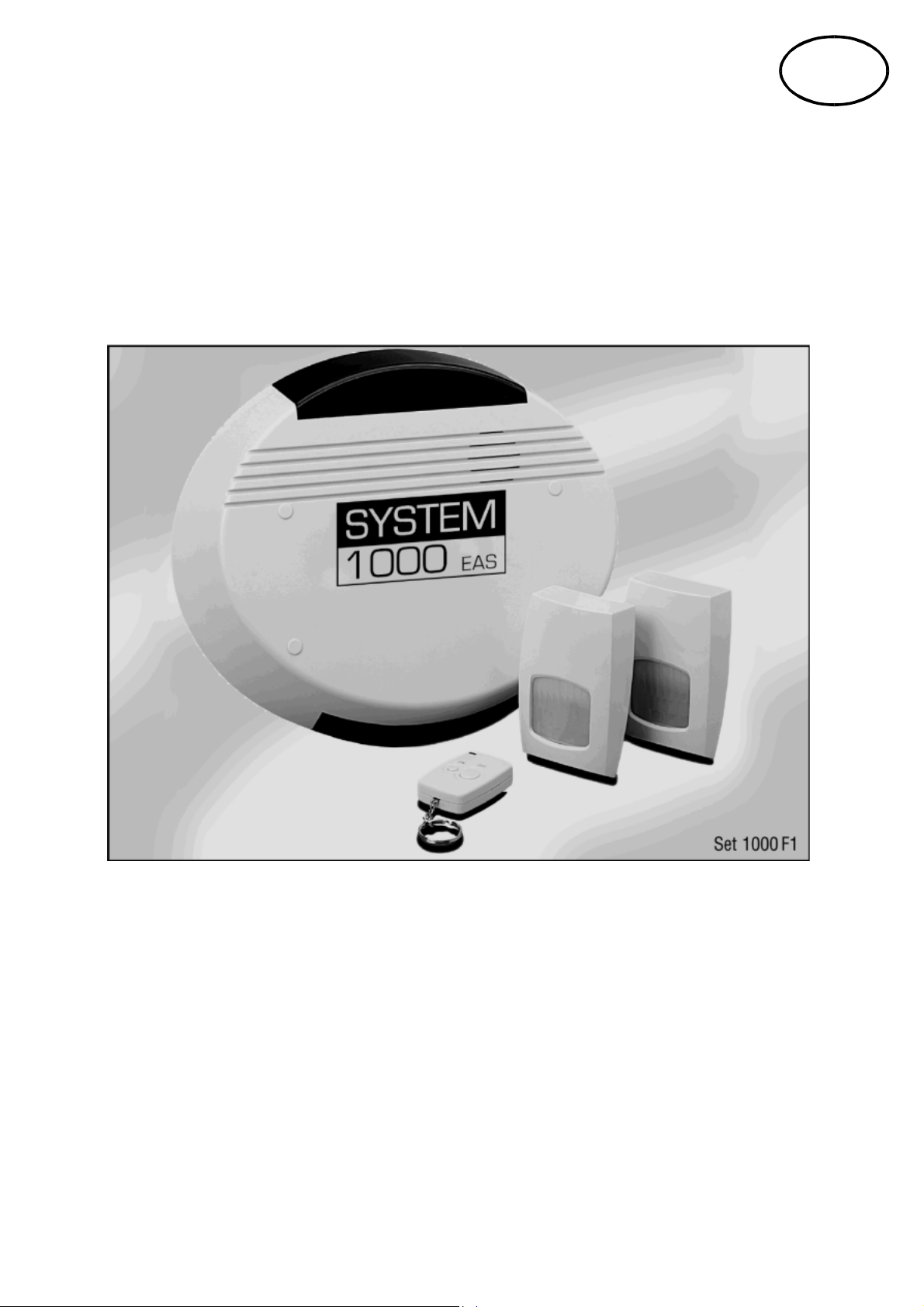
3. Kit Contents
Check the contents:
- siren
- RF keyfob
- 2 wirefree PIR sensors
- 4 self-adhesive sticky pads for the
PIRs
- 8 fixing screws and wall plugs
- installation and operating
instructions with drilling template
fig. 1
4. Safety Notes
• The PIRs must not come into contact with rain or humidity. They are suited for indoor use only.
• Before drilling, make sure that there are no electric cables hidden in the wall.
• As the siren is very loud, ensure that it is not operated close to a person’s ear (especially a child’s ear).
• Do not mount the control panel close to metal fittings or other objects which may disturb radio
signal transmission.
• Do not install any damaged units (e.g. by shipping damage). If in doubt, ask your customers service
or supplier. Repairs should be carried out by qualified persons or your customers service only.
• To clean the components, use a dry or moistened cloth. Do not dip the components into water.
• If the alarm system is not operated for a longer period of time, the batteries should be removed.
• Do not let children play with the components, and keep pets off the devices. Make sure that children
do not take individual parts into their mouth.
• Please read the battery safety notes carefully (see section 15.4).
Do not dispose of packaging material, used batteries or products as household waste. Please
use your recycling system. Details are available from your local authority.
5. Declaration of Conformity
Indexa GmbH declares the Wirefree Burglar Alarm SYSTEM 1000
complies with the standards of 1999/5/EG.
System1000_GB_130705.doc Page 2
6. How the System Works
The keyfob sends an RF signal which activates or deactivates the siren. In the armed state, when a PIR
senses a movement in its detection path, it sends an RF signal to the siren to activate. The siren then
sounds for two minutes, and the system is in the armed state again. The system may be deactivated at
any time with the keyfob. Always deactivate the system before entering your property.
A delay of 10 seconds enables you to activate or deactivate the system inside your property.
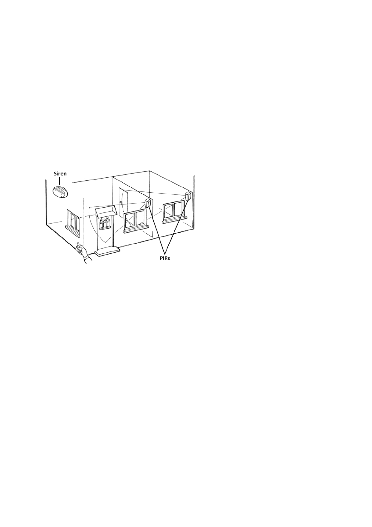
7. Planning your System
Before installing the components, you should plan their positions and check the function of the
components in these positions.
Fig. 2 shows an example:
fig. 2
Important points to consider:
- Do not mount the siren close to metal fittings such as metal downpipes or satellite dishes which may
affect radio signal transmission.
- The siren should be mounted at an outer wall, preferably in south direction, as this is where the solar
cells work best. Otherwise it can be mounted in east or west direction. North direction will work too,
but in this case the batteries will be used more. The solar cells also provide power when the sky is
cloudy. However, you should make sure that the solar cells are not placed in the shade of trees, walls
or roofs. Remember that the sun is in a lower position in the winter than in the summer.
- An anti-tamper switch protects the siren against tampering. However, you should install the siren as
high as possible to make tampering more difficult.
- The siren is for outdoor use, but it should be protected from direct rain.
- The siren should be installed at a place where it can reach the radio signals transmitted by the keyfob.
You should also be able to hear the bleeping sounds of the siren.
- Your property is monitored by PIR sensors located indoors. High security is not necessarily achieved by
a great number of sensors, but by reasonably installing them in key positions. Choose areas that will
probably be entered by a burglar, such as corridors, staircases or entrances.
- The PIRs must be fitted in radio range of the siren. The outdoor range is up to maximum 30m. This
range is reduced by walls and ceilings (especially reinforced concrete) as well as other sources of
interference, e.g. radio transmission from other devices in the frequency range of 433MHz such as
radio headsets. As such disturbances may change within a longer period of time, we recommend that
you install the PIRs within the maximum radio range. Whenever possible, locate the sensors as close
to the siren as you can.
- The PIRs react to warm moving bodies, e.g. a person’s movement within their detection range (up to
approx. 8m at 90° and a height of approx. 2,3m; see fig.3).
- A room can best be monitored, it the PIR is located in one of the corners.
- As the PIR reacts to warmth, it should not be positioned near a heat source such as radiators, air
conditioning, windows, stoves, fax machines or in draughty areas.
System1000_GB_130705.doc Page 3

- Pets may also trigger an alarm. When the system is armed, keep pets out of areas protected by PIR
sensors. If this is not possible, install the PIR upside down so that there is an area beneath the rays
left for the pet. In this case it is neccessary to check the detection range especially thoroughly.
- How quick a movement is detected depends also on the ambient temperature. A movement can be
detected more quickly in a cold environment.
- Movements that are at right angles to the PIR are detected more quickly than movements towards
the PIR. Install the PIRs in positions where a burglar would pass the PIR at right angles.
fig. 3
8. Accessories
The kit contains two PIRs and a wirefree remote keyfob. The system can easily be expanded by adding
additional PIRs. Additional keyfobs are also available. You can protect doors and windows with the door
contacts available as accessories. Accessory components must be adjusted to the codes of the original
system before use. This system will not work with wirefree accessories from other wirefree alarm systems
(see section 19 and 21).
9. Coding
For your security, each system is factory preset to an individual code. On the keyfob and PIRs are labels
with a row of numbers comprising of “0” and “1”. It is important that all the components have the same
identical row of numbers.This number is called the house code.
Please note your house code here:
Should you wish to expand your alarm system, you need this house code. If the numbers on the
components are not identical, please ask your supplier.
System1000_GB_130705.doc Page 4
10. Fitting the Batteries
We recommend you to use good quality alkaline batteries (e.g. Duracell).
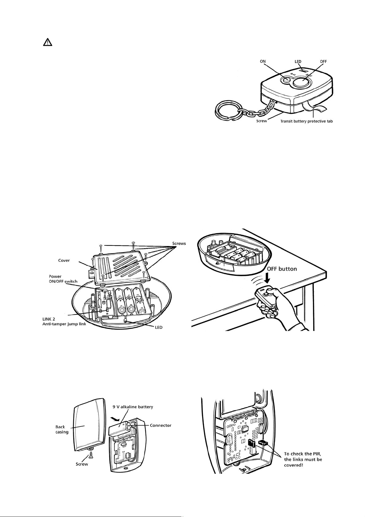
10.1. Keyfob
The keyfob is supplied with a 12V battery. Lightly
loosen the screw at the back side of the casing, and
pull out the transit battery protective tab. Retighten
the screw.
Press either the “ON” or “OFF” button to check that
the LED lights. If the LED does not light, the battery
may need replacing.
10.2 Siren
Remove the cover by releasing the six screws (see fig. 5). Switch the Power On/Off switch to the OFF
position. Check that the anti-tamper jump link covers both pins. (Factory set to cover both pins: antitamper circuit disabled.)
Insert six D-cell alkaline batteries (typeLR 20 or MN 1300) in the compartments so they face the same
direction and have the same polarity.
Now the siren must learn the house code from the keyfob. Turn the Power On/Off switch on the keyfob to
ON. The LED illuminates for 20 seconds, signalling the self-learn period.
Press the Power On/Off button on the keyfob within the 20 seconds.Two bleeps are heard, and the LED
goes out to confirm that the siren has learned the house code.
The siren can be operated with six or three batteries. If you use only three batteries, their operational life
is reduced accordingly. The batteries must be located in matched terminals, i.e. AAA or BBB.
fig. 4
fig. 5 fig. 6
10.3 PIR Sensors
Remove the screw to release the back casing. Place a 9V alkaline battery in the connector. Make sure that
both links are covered, so the PIR is in the test mode.
fig. 7 fig. 8
System1000_GB_130705.doc Page 5

11. Checking the Components
11.1 Keyfob
To arm the siren, press the ON button on the keyfob once. The siren emits a bleep, and the LED flashes
once. If the siren does not react, keep a minimum distance of 1m to the keyfob and press the ON button
once more.
To disarm the siren, press the OFF button on the keyfob. The siren bleeps twice, and the LED flashes.
11.2 Panic Alarm
The system has a panic alarm facility. Hold the keyfob ON or OFF button down for at least 3 seconds. The
siren will sound for 15 seconds. After this, the siren stops automatically. The siren cannot be silenced with
the keyfob if the panic alarm is activated.
WARNING: The siren is loud. Take precautions to prevent damage to your hearing.
11.3 PIR Sensors
First check the radio link to the siren. Place a
PIR sensor on a table or on the floor, and
wave a hand in front of the lens. The LED
behind the lens will flash (if the LED and the
power saver jump link are still covered). The
LED on the bottom of the siren should also
flash once.
Check that the PIR sensors activate the alarm.
To arm the siren, press the ON button on the
keyfob. The siren emits a bleep, and the LED
flashes once. After 10 seconds the siren emits
a second bleep. Now the system is armed!
Repeat the test with the PIR sensor, the siren
fig. 9
should trigger an alarm after 10 seconds.
To silence and to disarm the siren, press the
OFF button on the keyfob. The siren bleeps
five times, and the LED flashes once.
System1000_GB_130705.doc Page 6

12. Installation
12.1 Checking the Function of the System at the Place of Installation
Before installing the PIRs and the siren, repeat the steps described in section 11.3 with the components in
the positions where you want to install them (see “Planning your System”). Hold the components
provisionally in the intended positions, and check the detection range of the PIRs and the radio link to the
siren. If necessary, change the locations. If the system operates correctly, you can continue with the
installation.
12.2 Setting the PIR Sensors to Operating Mode
If you leave the LED operational jump link fitted (it
connects both pins), the LED behind the lens flashes
when the PIR sensor detects a warm moving body. This
is only important when you are installing the PIR. It
helps you to test the detection range at the place of
installation. If you are content with the installation, you
should remove the LED operational jump link and store
it by replacing it on one of the pins. Now the LED does
not flash, and battery power is saved.
When operating the system, you should also move the
power saver jump link from covering both pins, to
covering only one pin. The PIR will send a signal to the
siren when it is triggered, whether the system is armed
or not. Removing the power saver link provides an offperiod of approx. five minutes between two radio
fig. 10
12.3 Installation of the PIR sensors
fig. 11
The PIRs can be fixed to the wall with self-adhesive pads
supplied or with screws. Ensure that the casing screw is at the
bottom. If screwing to a flat wall, use the two predetermined
breaking points at the top and the bottom of the back casing. If
screwing to a corner, use the two predetermined breaking
points on the right and on the left of the back casing.
signals to save battery power. If you want to test your
system, you have to wait five minutes to avoid the
effects of the off-period.
After having installed and checked the PIR
sensors, you should remove both power saving
links in the PIR sensor. Otherwise
the batteries will be discharged too quickly.
Break through the holes, and use the back casing as a
template to mark the position for the fixing holes. Warning:
Before drilling, make sure that there are no electric cables
hidden in the wall. Drill the holes and use the masonry plugs
and screws supplied to fix the back casing to the wall. Clip the
PIR to the back casing and secure it with the casing screw.
When using self-adhesive pads, stick them to the back side of
the casing and press the PIRs firmly to the mounting surface.
fig. 12
System1000_GB_130705.doc Page 7

12.4 Setting the Siren to Operating Mode
The anti-tamper jump link is factory set in disable mode
with the jump link covering both pins.
If the siren is installed to an even surface, the anti-tamper
spring jump link is pressed down. If the siren is forced
from ist mounting, the anti-tamper switch will trigger an
alarm. If you want to enable the anti-tamper jump link,
make sure the switch stays pressed when the siren is
installed (check when the siren is mounted to uneven
surfaces). Remove the link from both pins and replace it
covering one pin.
With the battery fitted, the siren will sound. Press the OFF
button on the keyfob to silence the alarm. The LED lights
and the siren bleeps five times.
Now fix the cover using the six screws supplied. Do not
press the anti-tamper spring down otherwise it will reset
the alarm to activate. If this happens, press the OFF
button on the keyfob.
12.5 Installing the Siren
Use the template supplied (section 22), and mark the
positions for the four fixing holes. Check by the template
that the anti-tamper spring will not be positioned over a
hollow in the mounting surface. If it does, change the
fixing location or disable the anti-tamper switch by
covering both pins with the link.
Drill the four holes to a depth of 25mm and insert the
masonry plugs. Warning: Before drilling make sure that
there are no electric cables hidden in the wall. Drop the
four fixing screws supplied through the holes in the siren
and keep them in place with tape before you climb the
ladder. (This will help you find the location of the fixing
holes).
With the LED at the bottom, align the siren with the drilled
holes and secure it to the wall with the four fixing screws.
Fit the weatherproof caps over the screw holes.
WARNING: If the anti-tamper switch is enabled, do not lift
the siren off the mounting surface, otherwise the siren will
sound.
fig. 13
fig. 14
fig. 15
fig. 16
System1000_GB_130705.doc Page 8
fig. 17

13. System Operation
Action Command Confirmation
To arm Keyfob: Press the ON button Siren bleeps once, LED flashes
once. Further bleep after 10
seconds.
Panic alarm Keyfob: Hold down the ON or
OFF button for 3 seconds
To disarm Keyfob: Press the OFF button Siren bleeps twice (1), LED
(1) If the siren bleeps five times when disarmed, this is to warn you that an alarm has been triggered
during your absence.
Siren Tones
Tone Meaning
One bleep Armed
Two bleeps Disarmed
Two loud bleeps House code accepted
Five bleeps Disarmed, siren has been triggered
Full siren Siren sounds for 2 minutes (for 15 seconds in the
case of tampering), and then resets
automatically.
Siren sounds for 15 seconds
flashes once
14. Anti-Jamming
The System is fitted with an anti-jamming circuit. If it receives an unwanted radio signal for more than 30
seconds, it will trigger the siren for 15 seconds and then revert back to the previous status. The antijamming circuit is factory set in disable mode. If you wish to enable the anti-jamming circuit, cover both
pins of LINK 1 (factory set, the link covers only one pin). If the anti-jamming circuit often triggers an
alarm, you probably live in an area with strong radio interferences. In this case you should disable the
anti-jamming circuit by removing LINK 1 and replace it by covering only one pin.
fig. 18
System1000_GB_130705.doc Page 9

15. Changing the Batteries
15.1 Keyfob
When the LED on the keyfob does not light when you press the
ON/OFF buttons, the battery may need replacing. Remove the
fixing screw and separate the casing. Ensure the replacement
battery (12V, type 23 A) is correctly fitted (check for polarity),
and replace the case. Take care not to lose the chain retaining
pin.
fig. 19
15.2 PIR Sensors
If a red LED flashes behind the lens, the batteries need replacing. We recommend that you check the
batteries every six months and, if necessary, replace them (9V alkaline batteries). Note: Make sure that the
two links inside the PIRs cover only one pin (see section 12.2).
15.3 Siren
When the siren is operated normally, the LED flashes after each command. If the LED does not flash, the
batteries need to be replaced. The operational life of the batteries in the siren depends on the type of the
batteries, their use and the light conditions for the solar cells. Replace the batteries by six alkaline mono
cells of good quality.
15.4 Battery Safety Notes
- Use only alkaline batteries of good quality. Do not use rechargeable batteries because of their selfdischarge.
- Never insert old and new batteries together. (Always replace all batteries at the same time.)
- Use only batteries of the same type.
- Check that the batteries are correctly fitted regarding their polarity.
- Always remove old or used batteries from the components.
- Opening or burning batteries is highly dangerous.
- Never let children play with batteries. Swallowing batteries can lead to serious health problems.
- Do not short the battery poles.
System1000_GB_130705.doc Page 10

16. Troubleshooting
Problem Solution
Alarm sounds for no apparent reason. - Check that the batteries in the PIRs and the door contact
are correctly fitted and tightly connected.
When the batteries are almost empty, the
following may occur: If your are at home and the
PIR sensor detects your movements, the system
will become armed and the siren will sound. This
happens even though you have not armed the
system.
- If this happens, replace the batteries in the PIR sensors.
Check that the links have been removed (see section
12.2).
- The anti-tamper switch on the siren may be not fully
depressed. Place something underneath the switch,
reposition the siren or disable the anti-tamper spring
(see section 12.4).
- The anti-jamming circuit reacts to radio interferences.
Remove LINK 1 (see section 14).
The siren does not react to commands
transmitted by the keyfob.
The siren does not trigger an alarm. - Check arming by pressing the ON button.
- Check or change the keyfob battery.
- The distance between keyfob and siren is either too
short or too long.
- Consider that the PIRs have an off-period of 5 minutes.
Enter the detection range after 5 minutes.
- Consider the delay when entering or leaving your
property.
- Check or change the batteries in the siren.
- Check or change the batteries in the keyfob.
- The distance between the PIR or the keyfob and the
siren is too long. Shorten the distance.
- The radio link is disturbed.
17. Maintenance
We recommend that you check the batteries in the PIRs every six months and, if necessary, replace them.
The batteries can be checked by arming the system and triggering the sensor (remember the off-period of
the PIR). The siren should sound.
If the siren does not react or the siren tones are too faint, the batteries in the siren need replacing. We
recommend that you check the batteries in the siren every year.
The casing can be cleaned with a dry or moistened cloth. We recommend that you clean the cover of the
solar panel in the siren at least once a year.
18. Specifications
Siren 1000 ZS
Operating voltage: 4.5V DC
Power supply: solar cells (max. 5V) and 6 alkaline mono batteries 1.5V
Note: The system can also be operated with 3 mono batteries. With 3
batteries, the operational life is reduced accordingly.
Operational life of batteries: max. 2 years, depending on battery quality, use and light conditions
Mounting place: On an outer wall with the solar cells facing the sun. The siren should be
protected from direct rain.
Wirefree receiver: 433.92 MHz
Coding: self-learning code (10-digit)
LED display: to confirm commands
Siren: 105 dB(A)
Duration of alarm sound: max. 2 minutes; 15 seconds in case of tampering or jamming
Entry/exit delay: approx. 10 seconds
Anti-jamming circuit: The siren is triggered if the system receives an unwanted radio signal
for more than 30 seconds (can be enabled with LINK 1).
System1000_GB_130705.doc Page 11

Anti-tamper switch: Activates the siren if it is forced from its mounting (can be enabled with
LINK 2).
Operating temperature: -20°C to +40°C (typical)
Wirefree PIR sensor 1000 P
Sensor: passive infrared
Angular coverage: approx. 90°
Detection range: approx. 8m (mounting height of approx. 2.3m recommended)
Transmitter frequency: 433.92 MHz
Range: max. 30m (outdoors)
Coding: 10-digit code (wire links)
Operating voltage: 9 V DC
Battery: 9 V alkaline
Display: LED (can be disabled by removing the jump link)
Power saving: off-period of 5 minutes between signals (can be enabled with power
saver jump link)
Operating temperature: 0°C to 40°C
Use: indoors
Wirefree keyfob1000 R
Transmitter frequency: 433.92 MHz
Range: max. 30m (outdoors)
Coding: 10-digit code (wire links)
Operating voltage: 12 V DC
Battery: type 23A, 12 V
Display: LED
Operating temperature: -10°C to +50°C
19. Accessories
The system can be expanded with the addition of the following accessories:
wirefree keyfob 1000 R
wirefree PIR sensor 1000 P
wirefree door contact 1000 M (see section 21)
To convert the code into your house code, remove the wire links in the accessory components.
Instructions are supplied with the components.
fig. 20
System1000_GB_130705.doc Page 12

20. Guarantee Conditions
g
The following conditions that describe preconditions and extent of our guarantee leave the dealer’s
warranties according to the purchase contract untouched.
Before sending a product back or handing it to your dealer, please contact our helpline to discuss the
problem in advance. Maybe your problem can be solved by phone.
We offer the following guarantee to the first purchaser of this product:
- According to the following conditions (No. 2-7), we will repair any damage caused to the product
due to faulty workmanship, if it was reported to us immediately after noticing and within 24
months from delivery. This guarantee does not apply to minor differences from standard quality
that are irrelevant for value and performance capability of the product and to damage resulting
from chemical or electrochemical effects of water or abnormal environmental conditions.
- We will repair free of charge faulty parts or, at our discretion, exchange them for faultless parts.
Exchanged parts will become our property.
- The guarantee expires, if repairs or modifications are carried out by unauthorized persons or if our
products are provided with accessories that are not suitable for them. The guarantee also expires if
modifications of original parts are carried out.
- Repairs or exchanges carried out under guarantee do not extend the guarantee period and do not
start a new guarantee period. The guarantee period for spare parts ends with the guarantee period
for the complete product.
- The guarantee is always limited to the customary price of the product.
- Further claims, especially claims for damages that occur to persons or things other than the product
are excluded, as long as no liability is ordered by law. No compensation can be claimed in the case
of burglary or failure of the product.
- Please send the faulty product free of domicile. Shipments that are not free of domicile will not be
accepted. Repairs can only be carried out if an explicit description of the faults is supplied. Please
send in only complete systems that are well packaged.
NOTE: An alarm system can only be seen as a supplement to mechanical security measures. It is no
substitute for your duties of care and for sufficient insurance cover.
21. Appendix: Wirefree Door-Contact 1000 M (optional)
The optional door contact can be used to secure single doors or windows. The door contact contains a
reed contact that is closed by a magnet on the opposite side. If the magnet is removed, the contact
opens, and an alarm signal is transmitted to the siren.
21.1. Coding
When you receive the door contact, it is not factory preset to any special code. Please follow the
instructions on the packaging of the door contact 1000 M to adjust the code to your system.
21.2 Fitting the Battery
The door contact is supplied with a battery. To operate the door contact, slowly pull out the protective
tab. (If this is difficult, loosen the screws at the back of the casing, and retighten them after pulling out
the protective tab.)
fi
System1000_GB_130705.doc Page 13
. 21

21.3 Checking the Function
Place the door contact and the magnet so that the
arrows are facing towards each other. Arm the
system by pressing the ON button on the keyfob. The
siren bleeps once, and the LED flashes. After ten
seconds, the siren bleeps once again. Now the system
is armed. Pull the magnet away from the door
contact. The LED is green, and the siren should
trigger an alarm after an entry delay of ten seconds.
If the siren does not sound, check the battery and the
code. To silence the alarm and to disarm the system,
press the OFF button on the keyfob. Before installing
the door contact, also check the function in the
position where you want to install it.
21.4 Installation
The magnet is fixed to the door or window and the door contact to the door- or window frame (or vice
versa; this does not affect the function of the door contact). The parts can be installed on the right or left
side of a door or window; this does not affect the function either.
Advice: Installing the door contact on the bottom side of a window allows you to open the window at
the top without an alarm being triggered.
The two arrows can help you to bring the magnet and the door contact into line. The distance between
magnet and door contact should not exceed 5 mm.
fig. 22
fig. 23
fig. 24
System1000_GB_130705.doc Page 14

fig. 25
21.5 Changing the Battery
The parts should be arranged according to the kind of frame they are
fixed on (see fig. 24 and 25).
The parts can be fixed to the wall with the self-adhesive pads supplied or
with screws. When installing the door contact to a window, pay attention
to the length of the screws.
Then fit the four caps over the screw holes.
If the LED on the door contact flashes red when the
door contact is opened, the battery needs to be
replaced. Remove the two screws and separate the
casing. Insert a new battery (12 V, type 23A), and
replace the casing.
fig. 26
System1000_GB_130705.doc Page 15

position of the
anti-tamper spring
22. Drilling Template
- Hold the template to the mounting position, and check that it is horizontal.
- Mark the positions for the fixing holes.
- Remember that the casing of the siren is bigger than the template!
- The anti-tamper spring must be positioned on the same level as the back of the
casing, otherwise the siren will sound.
WARNING:
If the anti-tamper switch is enabled, do not take the siren off the wall after the antitamper spring is depressed. If the siren sounds, press the OFF button on the keyfob to
silence the alarm.
Indexa GmbH Paul-Böhringer-Str. 3 D – 74229 Oedheim
System1000_GB_130705.doc Page 16
 Loading...