

Page 1

Built-in hobs
Instructions for use and installation
P 640 TC (IX) GB
Page 2

Built-in hobs
Instructions for use and installation
Page 3
Congratualtions on choosing an Indesit appliance, which you will find is dependable and easy to use. We recommend
D
that you read this manual for best performance and to extend the life of your appliance. Thank you.
Contents
Contents...................................................................................................................................................... pag 1
Close-up View ...............................................................................................................................................pag 1
How To Use Y our Appliance ........................................................................................................................ pag 1
How to Keep Your Cooktop in Shape.... ...................................................................................................... pag 2
Is there a problem? ..................................................................................................................................... pag 2
Safety Is a Good Habit to Get Into .............................................................................................................. pag 3
Instructions for the installer ......................................................................................................................... pag 3
Is there a problem? ..................................................................................................................................... pag 2
Safety Is a Good Habit to Get Into .............................................................................................................. pag 3
Instructions for the installer ......................................................................................................................... pag 3-4
Instructions for the installer ......................................................................................................................... pag 5-6
Burners and nozzles characteristics.............................................................................................................pag 7
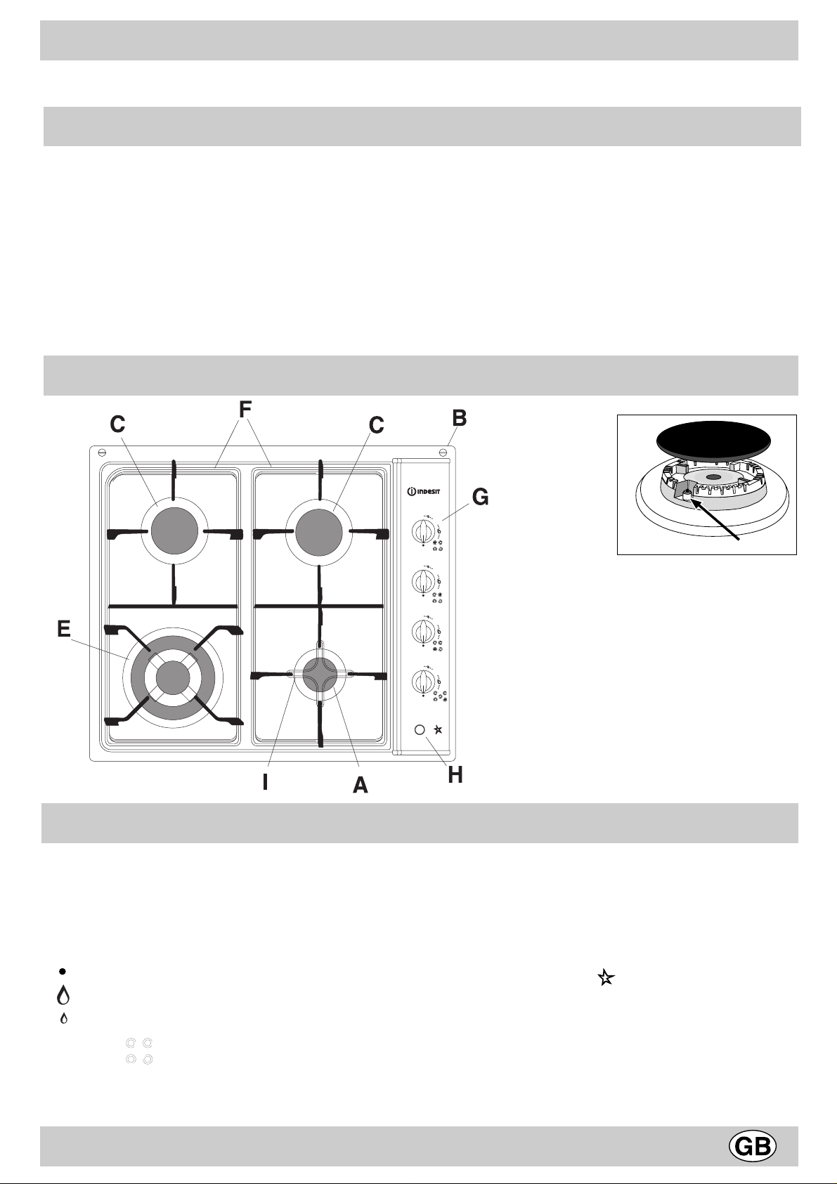
Close-up View
How To Use Your Appliance
Gas burners
The burners differ in size and power. Choose the most
appropriate one for the diameter of the cookware being used.
The burner can be regulated with the corresonding control
knob by using one of the following settings:
Off
High
Low
The symbols near the knobs also show the position of
the relative burner on the hob.
A Auxiliary gas burner
B Hooks
C Semi-fast gas burner
D Ignitor for Gas Burners
E Triple ring gas burner
F Support Grid for Cookware
G Control Knobs for Gas Burners
H Ignition Pushbutton for gas burners
I Pan reducing support
Lighting the burners
Automatic ignition "D":
• turn the relative knob counter-clockwise until the pointer
is on the high-flame symbol;
• press the automatic gas ignition by pushing the button
marked with the symbol ;
• Checking that the flame is stable. If it is not, repeat the
operation.
For minimum power, turn the knob towards the low flame
symbol. Intermediate positions are possible by putting the
knob anywhere between the high and the low flame symbol.
1
Page 4
To turn off the burner, turn the knob clockwise to the off
position “ “ .
• Difficulty in ignition is sometimes due to air inside the gas
duct.
• When the equipment is not in operation, check that the
knobs are in the off position “ “ . The main gas supply cutoff cock should also be closed.
Practical tips for using the burners
T o obtain maximum efficiency from the burners, it is advisable
to use only pans with a diameter that is suitable for the
burner being used, so that the flame does not extend beyond
the pan base (see following table).
When a liquid starts boiling, it is advisable to turn the flame
down just enough to keep the liquid simmering.
How to Keep Your Cooktop in Shape
renruB .mcninapehtforetemaiD
)llams(AyrailixuA41ot6morf
)muidem(Stsaf-imeS02ot51morf
)egral(TgnirelpirT03ot12morf
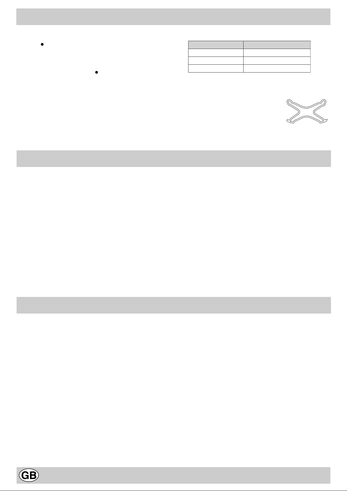
The hob is fitted with pan reducing
support (fig.1), which should only be
used on the auxiliary "A" burner (small).
fig.1
Before cleaning or performing maintenance on your
appliance, disconnect it from the electrical power supply .
To extend the life of the cooktop, it is absolutely
indispensable that it be cleaned carefully and thoroughly
on a frequent basis, keeping in mind the following:
• The enameled parts and the glass top, if present, must
be washed with warm water without using abrasive
powders or corrosive substances which could ruin them;
• The removable parts of the burners should be washed
frequently with warm water and soap, making sure to
remove caked-on substance. Check that the gas outlet
slits are not clogged. Dry the burners carefully before
using them again.
• Frequently clean the end part of the automatic glow plugs
of the hob.
• The steel parts and especially the areas with the screen-
Is there a problem?
It may occur that the cooktop does not function or does not
function properly. Before calling customer service for
assistance, lets see what can be done.
First of all, check to see that there are no interruptions in
the gas and electrical supplies, and, in particular, that the
gas valves for the mains are open.
The burner does not light or the flame is not uniform
around the burner.
Check to make sure that:
• The gas holes on the burner are not clogged;
• All of the movable parts that make up the burner are
mounted correctly;
• There are no draughts around the cooking surface.
The burner does not remain on when set to "Low".
Check to make sure that:
• The gas holes are not clogged.
• There are no draughts near the cooking surface.
• The minimum has been adjusted correctly (see the
section entitled, "Minimum Regulation").
printed symbols should not be cleaned with diluents or
abrasive detergents. It is advisable to use only a a damp
cloth with tepid water and a liquid detergent;
• Avoid cleaning appliance parts when they are still warm;
• Avoid leaving acidy liquids (vinegar, lemon juice, aggressive detergents, etc.) on enamelled or painted parts;
Greasing the Gas Valves
Over time, the gas valves may stick or become difficult to
turn. If this is the case, they must be cleaned on the inside
and then regreased.
Important: This procedure must be performed by a
technician authorized by the manufacturer.
The cookware is not stable.
Check to make sure that:
• The bottom of the cookware is perfectly flat.
• The cookware is centered correctly on the burner or
electric hot plate.
• The support grids have not been inverted.
If, despite all of these checks, the cooktop does not function
properly and problem persists, call the nearest Merloni Elettrodomestici Customer Service Centre, informing them of:
- The type of problem.
- The abbreviation used to identify the model (Mod. ...) as
indicated on the warranty .
Never call upon technicians not authorized by the
manufacturer, and refuse to accept spare parts that are not
original.
2
Page 5

Safety Is a Good Habit to Get Into
• This manual is for a class 3.
• This appliance is designed for non-professional use in
the home and its features and technical characteristics
must not be modified.
• The electrical system of this appliance is safe only when
it is correctly connected to an adequate earthing system,
as required by current safety standards.
Prevent children and the disabled from coming into
contact or having access to the following, as they are
possible sources of danger:
- The controls and the appliance in general;
- The packaging (plastic bags, polystyrene, nails, etc.);
- The appliance, during and immediately after use given
the heat generated by its use;
- The appliance when no longer in installed (in this case,
all potentially dangerous parts must be made safe).
The following should be avoided:
- Touching the appliance with wet parts of the body;
- Using the appliance with bare feet;
- Pulling on the appliance or the power supply cord to
disconnect them from the electrical outlet;
- Improper and/or dangerous use;
- Obstructing the ventilation or heat dissipation slots;
- Allowing the power supply cord of small appliances to
come into contact with the hot parts of the cooktop;
- Exposure to atmospheric agents (rain, sun);
- Using flammable liquids nearby;
- Using adaptors, multiple outlet plugs and/or extensions;
- Using unstable or deformed cookware;
- Leaving the electric hobs on without cookware on top of
them;
- Closing the glass top (if present) while the gas burners
are still hot;
- Trying to install or repair the appliance without the
assistance of qualified personnel.
The assistance of qualified personnel must be called
upon in the following cases:
- Installation (in accordance with the manufacturer's
instructions);
- When in doubt about the operation of the appliance;
- Replacement of the electrical outlet becuase it is
incompatible with the plug.
Contact service centers authorized by the manufacturer
in the following cases:
When in doubt about the condition of the appliance after
having removed the packing;
- Damage to or replacement of the power supply cord;
- In the case of a breakdown or malfunction: ask for original
spare parts.
It is recommended that you follow the guidelines below:
- Only use the appliance to cook food, avoiding all other
uses;
- Check the condition of the appliance after it has been
unpacked;
- Disconnect the appliance from the power supply in the
event of malfunction and always before cleaning or
maintenance;
- When not in use, disconnect the appliance from the power
supply and turn off the gas valve (if present);
- Always check to make sure that the control knobs are on
the " " setting when the appliance is not in use;
- Cut the power supply cord after disconnecting it from the
electrical mains when you decide to no longer use the
appliance.
The manufacturer will not be held liable for any damages
arising out of : incorrect installation or improper, incorrect or
unreasonable use.
Instructions for the installer
The following instructions are provided for qualified installers
so that they may accomplish installation, adjustment and
technical maintenance operations correctly and in
compliance with national current regulations and standards.
Important: the appliance should be disconnected from
the mains electricity supply before any adjustment,
maintenance, etc. is carried out. Maximum caution should
be used whenever it is necessary to keep the appliance
connected to the electricity supply .
The hobs have the following technical characteristics:
-Category II 2H3+ Class 3
Positioning
This appliance may only be installed and operated in
permanently ventilated rooms in compliance with provisions
laid down by current regulations and standards. The following
requirements must be observed:
The appliance must discharge combustion products into a
special hood, which must be connected to a chimney, flue
pipe or directly to the outside (fig.2). If it is impossible to fit a
hood, the use of an electric fan is permitted, either installed
on a window or on an external wall, which must be switched
on at the same time as the appliance.
fig.2
In a chimney stack or branched flue Directly to the outside
(exclusively for cooking appliances)
Kitchen ventilation
The air flow into the room where the appliance is installed
must equal the quantity of air that is required for regular
3
Page 6

Instructions for the installer
combustion of the gas and for ventilating the same room.
Air must be taken in naturally through permanent apertures
made in the outside walls of the room or through single or
branching collective ventilation ducts in compliance with the
standards in force. The air must be taken directly from the
outside, from an area far from sources of pollution.
The ventilation aperture must have the following
characteristics (fig.3A):
· total free cross section of passage of at least 6 cm² for
every kW of rated heating capacity of the appliance, with
a minimum of 100 cm² (the heating capacity is indicated
on the rating plate);
· it must be made in such a way that the aperture, both on
the inside and outside of the wall, cannot be obstructed;
· it must be protected, e.g. with grills, wire mesh, etc. in such
a way that the above-mentioned free section is not reduced;
· it must be situated as near to floor level as possible.
Detail A Adjacent Room to be
room ventilated
The hob must be at least 60 mm from the rear wall. If the
hob is to be installed near a corner, it must be at least 100
mm. from the side wall (fig.5). If the hob is installed on a
base unit with doors, hob operation is not influenced by the
opening and closing of these doors.
fig.4
A
Examples of ventilation holes Enlarging the ventilation slot
for comburant air between window and floor
Fig. 3A Fig. 3B
The air inflow may also be obtained from an adjoining room,
provided the latter is not a bedroom or a room where there
is a risk of fire, such as garages, mews, fuel stores, etc. and
is ventilated in compliance with the standards in force.
Air from the adjoining room to the one to be ventilated may
be made to freely pass through permanent apertures with a
cross section at least equal to that indicated above. These
apertures may also be obtained by increasing the gap
between the door and the floor (fig.3B). If an electric fan is
used for extracting the combustion products, the ventilation
aperture must be increased in relation to its maximum
performance. The electric fan should have a sufficient
capacity to guarantee an hourly exchange of air equal to 35 times the volume of the kitchen. Prolonged, intensive use
of the appliance may require extra ventilation, e.g. an open
window or a more efficient ventilation system by increasing
the extraction power of the electric fan if installed. Liquid
petroleum gas descends towards the floor as it is heavier
than air. Apertures in the outside walls in rooms containing
LPG cylinders should therefore be at floor level, in order to
allow any gas from leaks to be expelled. Do not store LPG
cylinders (even when empty) in basements/rooms below
ground level; it is advisable to keep only the cylinder in use
in the room at any one time and connected far from heat
sources which could raise its temperature to above 50 °C.
Fitting into modular kitchen units
For correct operation of the hob built into a kitchen unit or
other compartment, the latter must be suitable.
The installation diagram plus dimensions of the housing hole
is given in fig. 4.
fig.5
Installation above an oven
Suitable precautions must be taken to ensure that the
installation is in compliance with current accident-prevention
regulations regarding electrical and gas connections.
Both the electricity supply cable and the gas pipe must not
touch hot parts of the oven housing, in order to avoid
overheating. When installing above a built-under oven without
forced cooling ventilation, suitable air vents should be
provided for as shown in fig.6 (inlet at least 200 cm² from the
bottom, outlet at least 120 cm² from the top part) to allow
adequate ventilation inside the housing unit.
Also a wooden panel "A" should be installed beneath the
hob as insulation, positioning it at a minimum distance of 15
mm from the hob housing (fig.6).
Fixing to the housing unit
Proceed with fixing to the housing unit as follows (fig.7):
· mount the hooks "B", partly tightening the provided screws
"A" into the relative holes;
· position the provided sealing gasket "X" 5÷6 mm from the
edge of the installation hole, matching up the two ends of
4
Page 7

Instructions for the installer
appliance to the right (fig.8), or flexible steel pipe in compliance
with the standards in force, which must not exceed 2000 mm
in length. Should it be necessary to turn the fitting, the gasket
(supplied with the appliance) must be replaced.
Upon completion of installation, check the gas circuit, the
internal connections and the taps for leaks using a soapy
solution (never a flame). Also check that the connecting pipe
cannot come into contact with moving parts which could
damage or crush it. Make sure that the natural gas pipe is
adequate for a sufficient supply to the appliance when all the
burners are lit.
Important: A pressure regulator, in compliance with the
standards in force, must be inserted when connecting to a
liquid gas supply (in a cylinder).
fig.6
200 cm²
A
B
the seal without overlapping;
· insert the hob into the hole, making sure it is positioned
centrally and that the edge adheres to the sealant;
· position the hooks "B" correctly, as shown in figure and
then tighten the screws "A" to hold them in place;
Gas supply connection
Check that the appliance is set for the type of gas available
and then connect it to the mains gas piping or the gas
cylinder in compliance with current regulations and
standards.
This appliance is designed and set to work with the gas
indicated on the label situated on the actual hob. If the gas
supply is other than the type for which the appliance has
been set, proceed with replacing the corresponding nozzles
(provided), following instructions given in the paragraph
“Adaptation to different types of gas”.
For trouble-free operation, suitable use of energy and longer
life of the appliance, make sure that the supply pressure
complies with the values indicated in the table 1 "burners
and nozzles specifications, otherwise install a special
pressure regulator on the supply pipe in compliance with
current standards and regulations.
Connect in such a way that the appliance is subjected to
no strain whatsoever.
Either a rigid metal pipe with fittings in compliance with the
standards in force must be used for connecting to the nipple
union (threaded ½"G male fitting) situated at the rear of the
fig.8
fig.7
Adaptation to different types of gas
If the hob is to be converted for use with a type of gas other
than that for which it was set in the factory (indicated on the
label to be found on the hob), the burner nozzles should be
replaced as follows:
• Remove the pan supports and the burners.
• Unscrew the nozzles “A” (fig.9) using a 7 mm socket
wrench and replace them with the ones which have a
diameter suitable for the type of gas to be used, according
to the table 1 "burners and nozzles specifications".
• Reassemble the parts following the instructions in reverse
order.
• On completing the operation, replace the old rating label
with the one showing the new type of gas;
A
fig.9
Regulation of Air Supply to the Burner
The burners do not need any primary air regulator.
Minimum Regulation
· Put the tap to the low flame position;
· Remove the tap knob and turn the adjusting screw, situated
inside the tap stem (fig.10), using a screwdriver (loosening
the screw increases the height of the flame, tightening
decreases it).
note: the adjusting screw must be fully screwed down for
liquid gas.
· Having obtained the low flame setting required and with
the burner lit, abruptly change the position of the knob
several times from minimum to maximum and vice versa
and check that the flame does not go out.
· In the event of a malfunction on appliances with the security
device (thermocouple) when the gas supply is set at
minimum, increase the minimum supply levels using the
regulator screw.
fig.10
5
Page 8

Instructions for the installer
Electrical connection
THE APPLIANCE MUST BE EARTHED
The hob is designed to work with alternating current at the
supply voltage and frequency indicated on the rating plate
(situated under the hob or at the end of the instruction
booklet). Make sure that the local supply voltage corresponds
to the voltage indicated on the rating plate.
Connecting the supply cable to the mains electricity
supply
For models supplied without a plug, fit a standard plug,
suitable for the load indicated on the rating plate, onto the
cable and connect to a suitable socket.
T o connect directly to the mains supply , a double-pole switch
with a contact separation of at least 3 mm suitable for the
load and complying with current standards and regulations,
must be fitted between the appliance and the mains supply
outlet. The yellow-green earth wire must not be interrupted
by the switch. The supply cable must be in such a position
that no part of it can reach a temperature of 50°C above
room temperature. For installation above a built-under oven,
the hob and the oven must be connected separately to the
electricity supply both for safety reasons and for easy removal
of the oven if necessary. Do not use adapters or shunts as
they could cause heating or burning. Before connecting to
the power supply , make sure that:
• the limiter valve and the domestic system can withstand
the load from the appliance (see rating plate);
• the supply system is efficiently earthed according to
standards and laws in force;
• the socket or double-pole switch are easily accessible when
the appliance is installed.
Important: the wires in the mains lead are coloured in
accordance with the following code:
Green & Yellow - Earth
Blue - Neutral
Brown - Live
As the colours of the wires in the mains lead may not
correspond with the coloured markings identifying the
terminals in your plug, proceed as follows:
Connect the Green & Yellow wire to terminal marked “E” or
or coloured Green or Green & Yellow.
Connect the Brown wire to the terminal marked “L” or
coloured Red.
Connect the Blue wire to the terminal marked “N” or coloured
Black.
FAILURE TO OBSERVE THE ACCIDENT-PREVENTION
REGULA TIONS RELIEVES THE MANUF ACTURER OF ALL
LIABILITY.
Replacing the cable
Use a rubber cable of the type H05RR-F with a cross section
3 x 0.75 mm².
The yellow-green earth wire must be 2-3 cm longer than the
other wires.
Burners and nozzles characteristics
1elbaTsagdiuqiLsaglarutaN
renruBretemaiD
)mm(
.nimoN.cudeR03G***13G**02G
Cdipar-imeS5756.14.0034602181169751
AyrailixuA5500.13.0720537171759
EgnirelpirT03152.33.17519632232421903
ylppuS
erusserp
* At 15°C and 1013 mbar-dry gas
** Propane G31 H.s. = 50,37 MJ/kg
*** Butane G30 H.s. = 49,47 MJ/kg
Natural gas G20 H.s. = 37,78 MJ/m
rewoplamrehT
)*.s.H(Wk
3
ssap-yB
001/1
)mm(
rotcejnI
001/1
*wolF
h/g
)mm(
rotcejnI
001/1
*wolF
h/l
)mm(
)rabm(lanimoN03-827302
This appliance conforms with the following European
Economic Community directives:
- 73/23/EEC of 19/02/73 (Low Voltage) and subsequent
modifications;
- 89/336/EEC of 03/05/89 (Electromagnetic Compatibility)
and subsequent modifications;
- 90/396/EEC of 29/06/90 (Gas) and subsequent
modifications;
- 93/68/EEC of 22/07/93 and subsequent modifications.
6
Page 9

Page 10

Page 11

Page 12

Merloni Elettrodomestici
Viale Aristide Merloni 47
60044 Fabriano
Italy
Tel +39 0732 6611
Fax +39 0732 662501
www .merloni.com
09/01 - Cod. 195032114.01
 Loading...