

Indesit KP9F96S Operating Instructions Manual
Operating Instructions
COOKER
Contents
Installation, 2-6
Adjacent cabinetry
Electrical connection
Post Installation Checks
Technical specifications
Description of the appliance, 7
Overall view
Start-up and use, 8-11
Hob operation
Multi-function oven
Cooking tips
Cooking programmer, 12
Precautions and tips, 13-14
Practical advice on using the appliance
General Appliance Warnings
Installation Warnings
Safety With The Cooktop
Maintenance Warnings
Gas And Electrical Safety
Care and maintenance, 15-17
Switching the appliance off
Cleaning the appliance
Changing the oven light bulb
Disassembling the oven door
Cleaning The Cooktop
Service schedule
GB
KP9F96S /AUS
English, 1
GB
2
GB
Installation
! Before operating your new appliance please read
this instruction booklet carefully. It contains important
information concerning the safe operation, installation
and maintenance of the appliance.
! Please keep these operating instructions for future
reference. Pass them on to possible new owners of the
appliance.
The following instructions are provided for qualified
installers so that they may accomplish installation,
adjustment and technical maintenance operations
correctly and in compliance with current regulations
and standards.
Compliance with standards
This cooktop must be installed in accordance with
the requirements of local gas and electrical
authorities, as well as the latest published versions
of the following standards:
AS/NZS 5601 Gas Installation code
SAA Wiring Rules.
Important: the appliance should be disconnected
from the mains electricity supply before any
adjustment, maintenance, etc. is carried out.
Maximum caution should be used should it be
necessary to keep the appliance connected to the
electricity supply.
The appliance has the following technical
specifications:
Category: II 2H3+
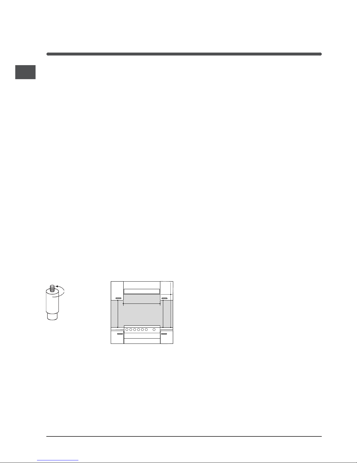
Adjacent cabinetry
The dimensions of the appliance are given in the
figure on page 2, and the location of connection
point sin the table on page 10 . For trouble-free
operation of appliances installed in housing units,
the minimum distances shown in fig.4 should be
observed. It is recommended that the adjacent
kitchen surfaces should be capable of withstanding
temperatures of 65°C. Also, the following must be
observed:
The appliance should be installed next to
cabinetry which is no taller than the top of the
cooker hob.
The wall in direct contact with the back panel of
the cooker must be made of non-flammable
material. During operation of the cooker, the back
panel of the cooker could reach a temperature of
50°C above room temperature.
Kitchen cabinets installed next to the cooker that
are higher than the top of the hob, must be at
least 600 mm from the edge of the hob itself.
If the hood is installed below a wall cabinet, the
latter must be at least 700 mm (millimetres) above
the surface of the hob.
Cabinets installed adjacent to the hood must be
at least 420 mm above the hob,
The following minimum clearances to combustible
materials must be observed:
Minimum clearance from edge of burner to side
wall must be 200 mm.
Minimum clearance from edge of burner to rear wall
must be 200 mm.
In the lower part of the cooker there are 4 height
adjustable screw-in feet with which it is possible to
level the cooker if necessary.
Kitchen ventilation
Where the total input of all appliances exceeds 3
MJ/h for each cubic metre of the room or enclosure
volume, the space shall be ventilated by one of the
methods detailed below. For the purpose of
assessing the adequacy of ventilation, the space
that cannot be isolated by doors is the volume of a
room.
Natural ventilation direct from outside
Two permanent openings shall be provided directly
to outside. The openings shall be located to ensure
the distance between the top of the upper opening
and the ceiling of the room or enclosure, and the
distance between the bottom of the lower opening
and the floor of the room or enclosure does not
exceed 5% of the height of the room or enclosure.
The minimum free ventilation area provided by each
opening shall be calculated using the following
formula:
A = 3 × T
where
A = the minimum free ventilation area (cm
2
)
T = the total gas consumption of all appliances
(MJ/h)
The minimum vertical dimension of any free
ventilation opening shall be 6 mm.
NOTE 1 When used in this Clause, the term directly
to outside means any one of the following options,
provided that the ventilation path is unobstructed by
building material or insulation:
(a) Directly through an outside wall (preferred
option).
HOOD
420
Min.
min.
650
mm. with hood
min.
700
mm. without hood
mm.
600
Min. mm.
420
Min. mm.
GB
3
(b) Through to an outside wall but offset.
(c) Into a cavity ventilated to outside.
(d) Into an underfloor space ventilated to outside.
(e) Into a roof space ventilated to outside.
NOTE 2 The two openings may be combined
provided that the top and bottom of the opening
reach the limits set by this Clause.
Natural ventilation via adjacent room
Two permanent openings shall be provided in the
room or enclosure. The openings shall be located to
ensure the distance between the top of the upper
opening and the ceiling of the room or enclosure,
and the distance between the bottom of the lower
opening and the floor of the room or enclosure does
not exceed 5% of the height of the room or
enclosure.
The minimum free ventilation area provided by each
opening shall be calculated using the following
formula:
A = 6 × T
where
A = the minimum free ventilation area (cm
2
)
T = the total gas consumption of all appliances
(MJ/h)
These requirements shall apply to all subsequent
rooms until a room is ventilated to outside, in
accordance with the previous section, or the total
input of the appliances does not exceed 3 MJ/h for
each cubic metre of the total volume of the
enclosure and rooms.
The minimum vertical dimension of any free
ventilation opening shall be 6 mm.
NOTE: The two openings may be combined
provided that the top and bottom of the opening
reach the limits set by this Clause.
If an electric fan is used for extracting the
combustion products, the ventilation aperture must
be increased in relation to its maximum
performance. The electric fan should have a
sufficient capacity to guarantee an hourly exchange
of air equal to 3 ÷ 5 times the volume of the kitchen.
Prolonged, intensive use of the appliance may
require extra ventilation, e.g. an open window or a
more efficient ventilation system by increasing the
extraction power of the electric fan if installed. Liquid
petroleum gas descends towards the floor as it is
heavier than air. Apertures in the outside walls in
rooms containing LPG cylinders should therefore be
at floor level, in order to allow any gas from leaks to
be expelled. Do not store LPG cylinders (even when
empty) in basements or rooms below ground level; it
is advisable to keep only the cylinder in use in the
room at any one time and connected far from heat
sources which could raise its temperature to above
50 °C.
Range hoods
Range hoods and overhead exhaust fans must be
installed according to manufacturers instructions
but in no case shall clearance from hob burners be
less than 600 mm for range hoods and 750 mm for
overhead exhaust fans.
If the hood is installed below a wall cabinet, the
latter must be at least 700 mm (millimetres) above
the surface of the hob.
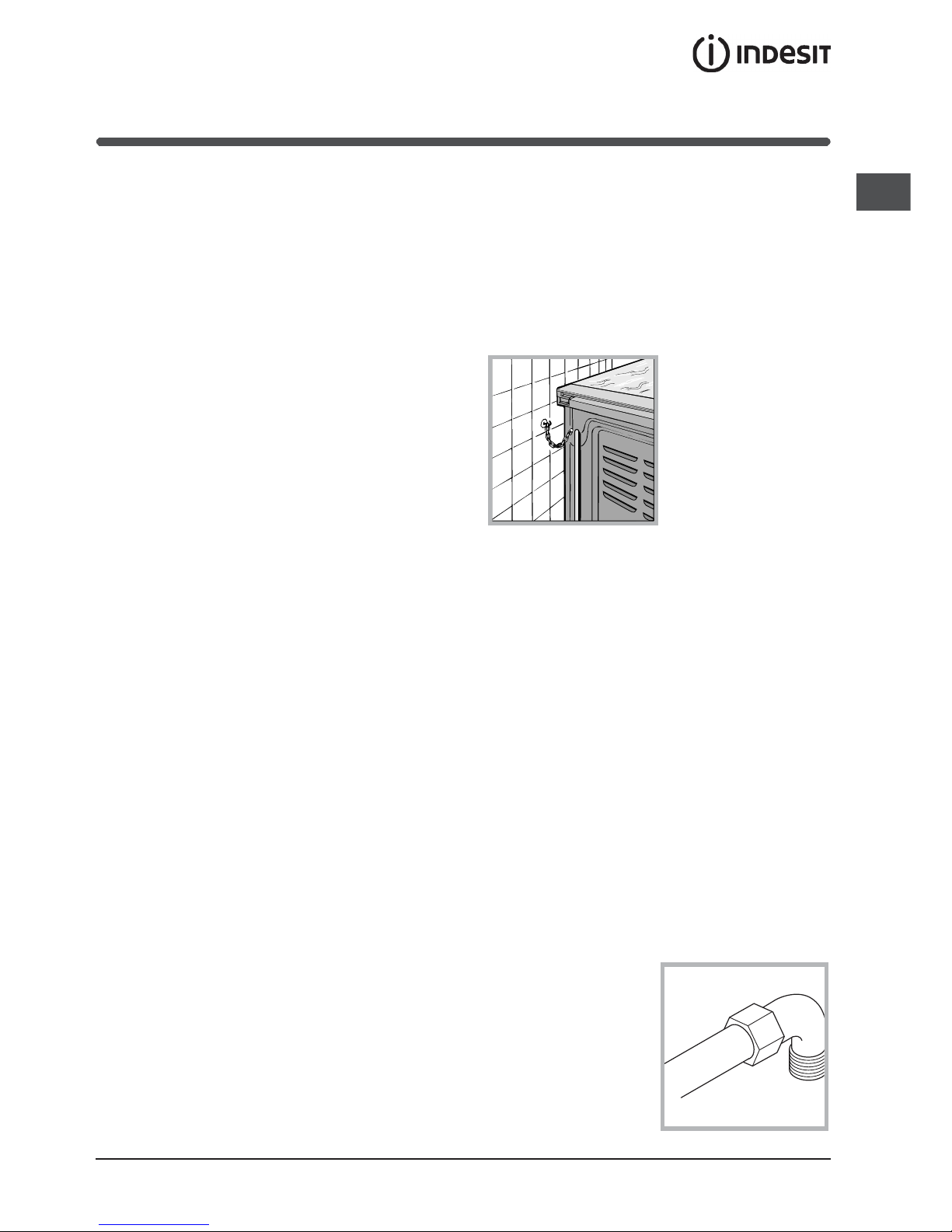
Safety Chain
In order to prevent
accidental tipping of
the appliance, for
example by a child
climbing onto the open
oven door, the supplied
safety chain must be
installed.
Ensure the chain is
secured to the rear wall
of the oven, and attach
the chain to a hook or screw secured to the wall
behind the appliance.
NOTE: If the cooker is placed on a base, measures
must be taken to prevent the appliance slipping
from the base.
This appliance is suitable for use with either a
flexible connection or rigid copper connection.
Check The Gas Type
! Before installation, check that the gas type (natural
gas or LPG/Propane) of the cooker is suitable for the
gas type available to the installation. It is extremely
dangerous to use the wrong gas type with any
appliance, as fire or serious injury can result.
This cooker is supplied from the factory already set
for Natural Gas. To convert the cooker to LPG (or
back to Natural Gas from LPG), follow the directions
later in this section.
Fit regulator supplied for Natural Gas (if applicable)
at rear of appliance, and as close as practicable to
the appliance.
It is recommended that an isolating valve and union
be fitted, to enable simple disconnection for
servicing. These are to be in an accessible location.
Either a rigid metal pipe
with fittings in
compliance with the
standards in force must
be used for connecting
to the nipple union
(threaded ½G male
fitting) situated at the
rear of the appliance to
the right, or an
4
GB
approved flexible hose of class B or D.
Should it be necessary to turn the fitting, the gasket
(supplied with the appliance) must be replaced.
If a flexible hose is used, it should be as short as
possible with a maximum length of 1.5 metres;
The flexible connection must be approved to
class B or D of AS/NZS1869 as a minimum.
it should not be bent, kinked or compressed;
it should not be in contact with the rear wall of the
appliance or in any case with parts which may
reach a temperature of 50°C;
it should not come into contact with pointed parts
or sharp corners;
it should not be subject to any pulling or twisting
forces;
it should be easy to inspect along its entire length
in order to be able to check its condition.
The supply connection point must be accessible
with the appliance installed.
The inner diameters of the pipe are as follows:
8 mm for LPG;
13 mm for Natural Gas.
Upon completion of installation, check the gas
circuit, the internal connections and the taps for
leaks using a soapy solution (never a flame). Also
check that the connecting pipe cannot come into
contact with moving parts which could damage or
crush it. Make sure that the natural gas pipe is
adequate for a sufficient supply to the appliance
when all the burners are lit
! A pressure regulator, in compliance with the
standards in force, must be inserted when
connecting to a liquid gas supply (in a cylinder).
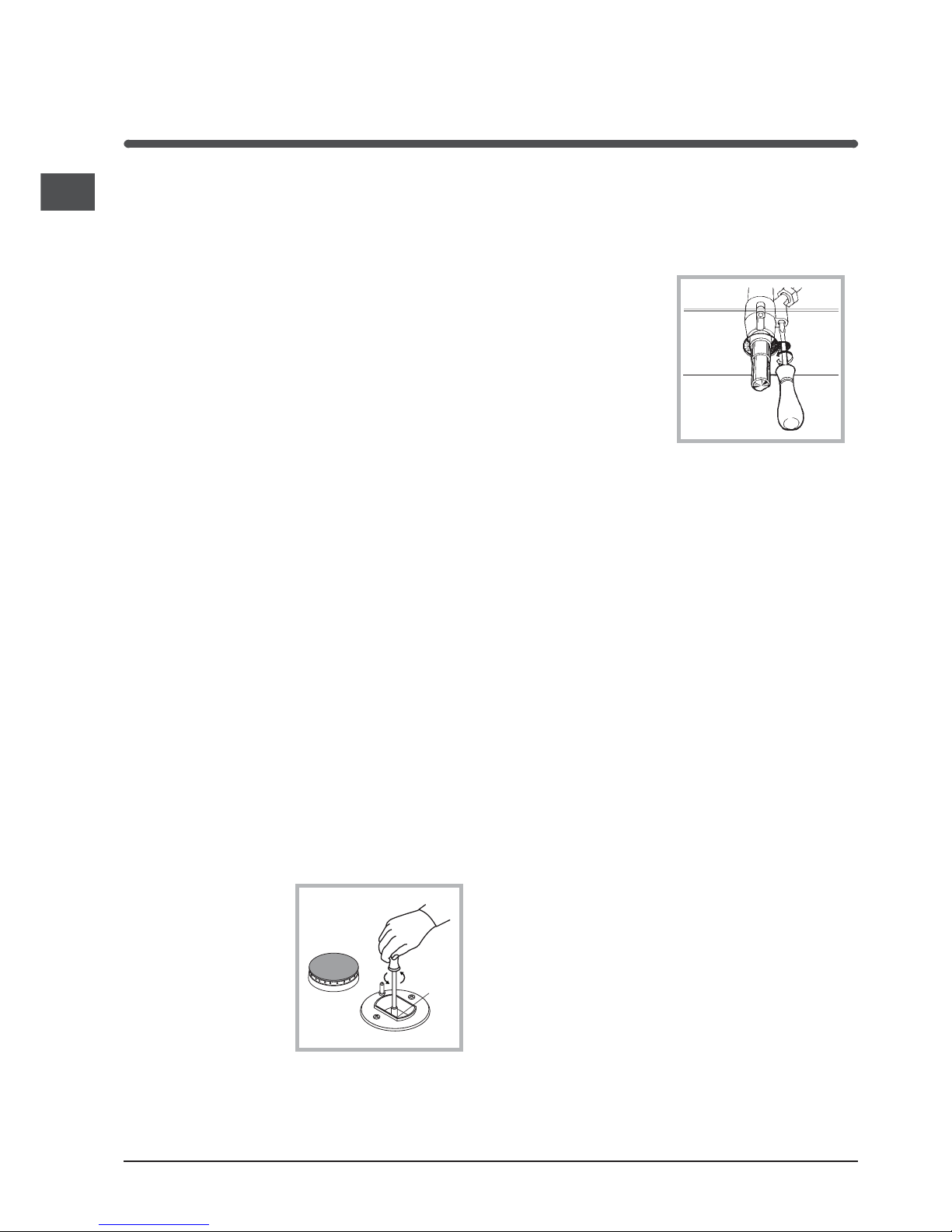
Adapting to different types of gas
To adapt the hob to a different type of gas from the
factory-set one (indicated on the rating plate at the
top of the hood or on the packaging), the burner
nozzles should be replaced as follows:
Remove the hob grids and slide the burners off
their seats.
Unscrew the nozzles (see figure), using a 7 mm
socket spanner and
replace them with
nozzles for the new
type of gas (see
table 1 "Burner and
nozzle
characteristics").
Reassemble the
parts following the
above procedure in
the reverse order.
On completing the operation, replace the old
rating label with the one showing the new type of
gas; the sticker is available from our Service
Centres.
Adjusting the primary air of the burners The
primary air of the burners does not need to be
adjusted.
Adjusting the low flame
Turn the tap to the low flame position;
Remove the knob
and turn the
adjusting screw,
situated to the right
of the tap (see figure)
until you obtain a
regular small flame,
using a screwdriver
(loosening the screw
increases the height
of the flame,
tightening decreases it).
N.B.: In the case of liquid gas, the regulation
screw must be screwed in all the way.
Having obtained the low flame setting required
and with the burner lit, abruptly change the
position of the knob several times from minimum
to maximum and vice versa and check that the
flame does not go out.
In appliances fitted with the safety device
(thermocouple), should the device fail to work with
the burners set to the low flame setting, increase the
low flame setting of the same on the adjusting
screw.
Once the adjustment has been made, remount the
seals on the by-passes using sealing wax or similar.
Duplicate Data Plate
Where the data plate is obscured by cabinetry when
the cooker is in the installed position, place a
duplicate data plate on a surface of the cabinetry
adjacent to the cooker.
Electrical connection
THE APPLIANCE MUST BE EARTHED
The appliance is designed to work with alternating
current at the supply voltage and frequency
indicated on the rating plate (situated on the rear
part of the appliance and on the last page of the
instruction booklet) or at the end of the instruction
booklet. Make sure that the local supply voltage
corresponds to the voltage indicated on the rating
plate.
ATTENTION: This appliance has a maximum
power exeeding 3kW; it is therefore necessary for
it to be connected to a socket able to support a
rated current higher than 13A (the appliance rated
current is 15A). Connecting the supply cable to
A
GB
5
the mains electricity supply A 13.
To connect directly to the mains supply, a doublepole switch with a contact separation of at least 3
mm suitable for the load and complying with current
standards and regulations, must be fitted between
the appliance and the mains supply outlet. The
yellow-green earth wire must not be interrupted by
the switch. The supply cable must be in such a
position that no part of it can reach a temperature of
50 °C above room temperature. Do not use adapters
or shunts as they could cause heating or burning.
Before connecting to the power supply, make sure
that:
the limiter valve and the domestic system can
withstand the load from the appliance (see rating
plate);
the supply system is efficiently earthed according
to standards and laws in force;
the socket or double-pole switch are easily
accessible when the appliance is installed.
FAILURE TO OBSERVE THE ACCIDENTPREVENTION REGULATIONS RELIEVES THE
MANUFACTURER OF ALL LIABILITY.
Important: the wires in the mains lead are coloured
in accordance with the following code:
Green & Yellow - Earth
Blue - Neutral
Brown - Live
As the colours of the wires in the mains lead may
not correspond with the coloured markings
identifying the terminals in your plug, proceed as
follows:
Connect the Green & Yellow wire to terminal marked
E or
or coloured Green or Green & Yellow.
Connect the Brown wire to the terminal marked L or
coloured Red.
Connect the Blue wire to the terminal marked N or
coloured Black.
Post Installation Checks
Perform post installation checks and ensure proper
and safe operation before leaving. Test all burners
individually and in combination.
Leak Check
Ensure all gas control knobs are in the Off
position.
Ensure the gas supply is switched on.
Spray a solution of soapy water onto all gas joints
as well as the full length of any flexible hoses.
UNDER NO CIRCUMSTANCES USE A NAKED
FLAME IN CHECKING FOR LEAKS.
If bubbles appear anywhere, turn the gas supply off,
check all connections and retest. If satisfactory
operation cannot be achieved, contact place of
purchase or their appointed agent for service.
Flame check
Turn each burner on, and ensure that the flame is
blue with minimal yellow tipping. If there is
significant yellow tipping, flame lift off or excessive
noise, check pressure and adjust at the regulator if
necessary.
If satisfactory operation cannot be achieved, contact
place of purchase or their appointed agent for
service.
Igniter operation
Check that the igniter for each burner successfully
ignites the gas.
If an igniter fails to work, first remove the plug from
the electrical power outlet, and then check that all
the electrical connections are in place.
If satisfactory operation cannot be achieved, contact
place of purchase or their appointed agent for
service.
Low flame setting
Check the low flame setting for each hob burner to
ensure that the minimum flame will not be
extinguished by air draughts.
Light the burner.
Turn the control until it engages in the minimum
position.
Ensure the flame is stable and will not be
extinguished by air draughts.
To adjust the minimum flame:
Follow the procedure described in the gas
conversion instruction.
DO NOT MODIFY THIS APPLIANCE IN ANY WAY,
OTHER THAN AS DESCRIBED IN THESE
INSTRUCTIONS.
Disconnecting the cable
Ensure that the means for disconnection of the
power cable is incorporated intot he fixed wiring in
accordance with local wiring rules.
(New Zealand statutory warning): The cooker must
be connected to the electricity supply by a cable
fitted with an appropriately rated plug that is
compatible with the socket-outlet fitted to the final
subcircuit in the fixed wiring that is intended to
supply this cooker.
Replacing the cable
Use a rubber cable of the type H05VV-F with a
suitable cross section 3 x 1.5 mm².
The yellow-green earth wire must be 2-3 cm longer
than the other wires.
6
GB
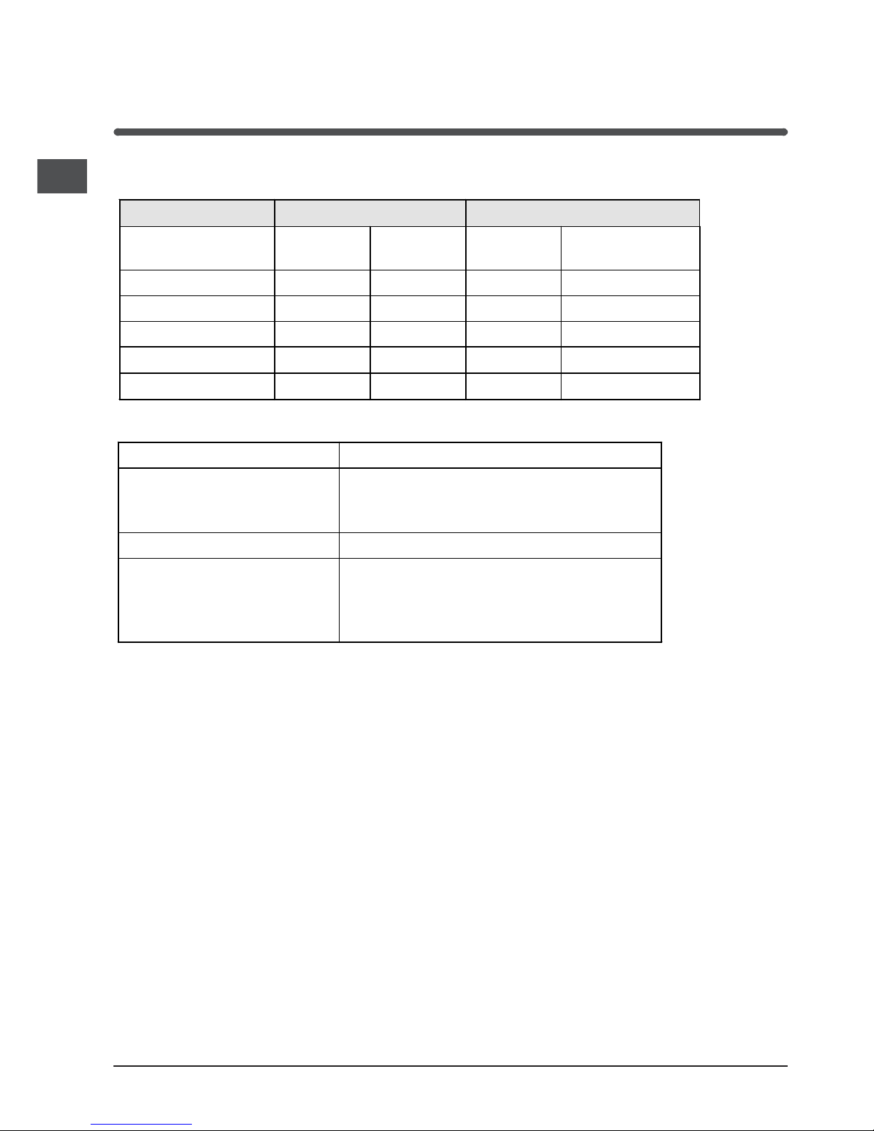
TECHNICAL SPECIFICATIONS
Gas Consumption
Natural Gas (1.0 kPa) ULPG (2.75 kPa)
Injector
Diameter
Gas Input
Injector
Diameter
Gas Input
Auxiliary Burner A 0.80 mm 3.3 MJ/hr 0.50 mm 3.5 MJ/hr
Semi Rapid Burner B 1.10 mm 6.0 MJ/hr 0.64 mm 5.5 MJ/hr
Rapid Burner C 1.29 mm 8.3 MJ/hr
0.80 mm 9.0 MJ/hr
Triple Ring Burner D 1.75 mm 15.0 MJ/hr 1.05 mm 15.0 MJ/hr
Total 38.6 MJ/hr 38.5 MJ/hr
Connections
Gas Inlet fitting 1/2 BSP (male) thread
Location of gas inlet Bottom rear of upright cooker
90 mm C/L from RH side (as viewed from front)
600 mm from base of upright cooker
Electrical input Flexible cord and earthed 10 Amp 3 pin plug
Location of Electrical Connection Rear of upright cooker
90 mm C/L from left hand side (as viewed from
front)
90 mm from base (without legs installed)
 Loading...