

Indesit KP900GX User Manual
Operating Instructions
Contents
GB
Installation, 2-5
English,2
KP900GX
Room ventilation
Disposing of combustion fumes
Positioning and levelling
Electrical connection
Gas connection
Table of burner and nozzle specifications
Table of characteristics
Description of the appliance, 6
Overall view
Control panel
Start-up and use, 7-11
Using the hob
Setting the time
Using the oven
Cooking modes for Multi-function (1rst Oven)
Cooking modes for conventional-function (2nd Oven)
Practical cooking advice
Oven cooking advice table
COOKER AND OVEN
GB
Precautions and tips, 12
General safety
Disposal
Respecting and conserving the environment
Care and maintenance, 13
Switching the appliance off
Cleaning the appliance
Replacing the oven light bulb
Gas tap maintenance
Assistance
Installation
GB
! Before operating your new appliance please read
this instruction booklet carefully. It contains
important information concerning the safe installation
and operation of the appliance.
! Please keep these operating instructions for future
reference. Make sure that the instructions are kept
with the appliance if it is sold, given away or moved.
! The appliance must be installed by a qualified
professional according to the instructions provided.
! Any necessary adjustment or maintenance must be
performed after the cooker has been disconnected
from the electricity supply.
Room ventilation
The appliance may only be installed in permanentlyventilated rooms, in accordance with current national
legislation. The room in which the appliance is
installed must be ventilated adequately so as to
provide as much air as is needed by the normal gas
combustion process (the flow of air must not be
lower than 2 m3/h per kW of installed power).
The air inlets, protected by grilles, should have a
duct with an inner cross section of at least 100 cm2
and should be positioned so that they are not liable
to even partial obstruction (see figure A).
These inlets should be enlarged by 100% - with a
minimum of 200 cm2 - whenever the surface of the
hob is not equipped with a flame failure safety
device. When the flow of air is provided in an indirect
manner from adjacent rooms (see figure B), provided
that these are not communal parts of a building,
areas with increased fire hazards or bedrooms, the
inlets should be fitted with a ventilation duct leading
outside as described above.
Adjacent room Room requiring
ventilation
AB
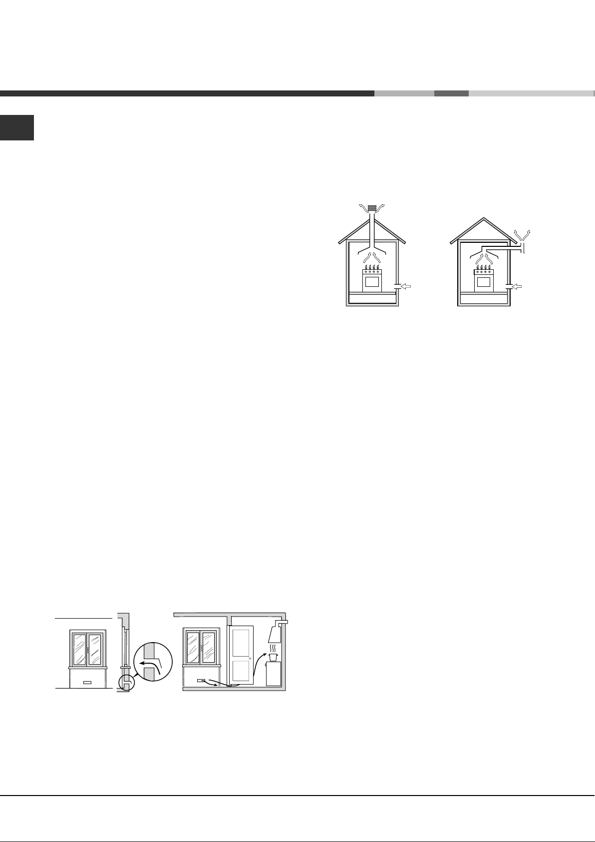
Disposing of combustion fumes
The disposal of combustion fumes should be
guaranteed using a hood connected to a safe and
efficient natural suction chimney, or using an electric
fan that begins to operate automatically every time
the appliance is switched on (see figure).
Fumes channeled outside
Fumes channelled through straight a
chimney or a branched flue system
(reserved for cooking appliances)
! The liquefied petroleum gases are heavier than air
and collect by the floor, therefore all rooms containing
LPG cylinders must have openings leading outside so
that any leaked gas can escape easily.
LPG cylinders, therefore, whether partially or
completely full, must not be installed or stored in
rooms or storage areas that are below ground level
(cellars, etc.). Only the cylinder being used should be
stored in the room; this should also be kept well
away from sources of heat (ovens, chimneys,
stoves) that may cause the temperature of the
cylinder to rise above 50°C.
Positioning and levelling
! It is possible to install the appliance alongside
cupboards whose height does not exceed that of the
hob surface.
! Make sure that the wall in contact with the back of
the appliance is made from a non-flammable, heatresistant material (T 90°C).
A
Ventilation opening Increase in the gap between
for comburent air the door and the flooring
! After prolonged use of the appliance, it is advisable
to open a window or increase the speed of any fans
used.
2
To install the appliance correctly:
• Place it in the kitchen, the dining room or the bedsit (not in the bathroom).
• If the top of the hob is higher than the cupboards,
the appliance must be installed at least 600 mm
away from them.
• If the cooker is installed underneath a wall cabinet,
there must be a minimum distance of 420 mm
between this cabinet and the top of the hob.
This distance should be increased to 700 mm if the
wall cabinets are flammable (see figure).
mm.
420
Min.
HOOD
Min. mm.
900
• Do not position
blinds behind the
cooker or less than 200
mm away from its
sides.
mm. with hood
mm. without hood
420
• Any hoods must be
650
700
Min. mm.
installed according to
min.
min.
the instructions listed in
the relevant operating
manual.
Green & Yellow wire to terminal marked “E” or
or coloured
Green or Green & Yellow.
Brown wire to terminal marked “L” or coloured Red.
Blue wire to terminal marked “N” or coloured Black (see fig.
B).
l fix the feeding cable in the special cable stop and
close the cover.
N.B.: the power supply cable must have these minimum
requirements:
Type: H05RR-F
Section: 3x2.5 mm
2
GB
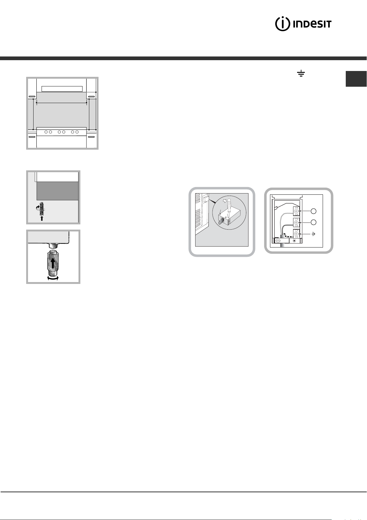
Levelling
If it is necessary to level the
appliance, screw the
adjustable feet into the places
provided on each corner of the
base of the cooker (see
figure).
The legs* fit into the slots on
the underside of the base of
the cooker.
Electrical connection
WARNING – THIS APPLIANCE MUST BE EARTHED.
Electrical connection
Electric cookers come without a power supply cable. The
cooker is designed to operate on an electricity supply which
conforms to the electrical data shown on the Rating Plate. The
cooker can be connected to the mains only after removing
the back panel of the cooker itself with a screwdriver.
N.B.: the following installation procedure must be carried out
by a qualified electrician. The electrical installation must comply
with the IEE Regulations, Building & local By-Lays.
For the installation of the feeding cable carry out the following
operations:
l Using a screwdriver, prise on the side tabs of the
terminal board cover (see fig. A);
l Pull and open the junction blok lid
Important: the wires in the mains lead are coloured in
accordance with the following code:
Green & Yellow -Earth
Blue -Neutral
Brown -Live
As the colours of the wires in the mains lead may not
correspond with the coloured markings identifying the
terminals in your plug, proceed as follows:
Ensure that the mains cable is routed away from any brackets
affixed to the rear panel and is not trapped to the rear wall
when pushing the cooker into position between cabinets.
L
2
N
4
Fig. A
Fig. B
Gas connection
Connection to the gas network or to the gas cylinder
may be carried out using a flexible rubber or steel hose,
in accordance with current national legislation and after
making sure that the appliance is suited to the type of
gas with which it will be supplied (see the rating sticker
on the cover: if this is not the case see below). When
using liquid gas from a cylinder, install a pressure
regulator which complies with current national
regulations. To make connection easier, the gas supply
may be turned sideways*: reverse the position of the
hose holder with that of the cap and replace the gasket
that is supplied with the appliance.
! Check that the pressure of the gas supply is
consistent with the values indicated in the Table of
burner and nozzle specifications (see below). This
will ensure the safe operation and durability of your
appliance while maintaining efficient energy
consumption.
Gas connection using a flexible rubber hose
Make sure that the hose complies with current
national legislation. The inter nal diameter of the hose
must measure: 8 mm for liquid gas supply; 13 mm for
methane gas supply.
Once the connection has been performed, make sure
3
GB
that the hose:
• Does not come into contact with any parts that
reach temperatures of over 50°C.
• Is not subject to any pulling or twisting forces and
that it is not kinked or bent.
• Does not come into contact with blades, sharp
corners or moving parts and that it is not
compressed.
• Is easy to inspect along its whole length so that its
condition may be checked.
• Is shorter than 1500 mm.
• Fits firmly into place at both ends, where it will be
fixed using clamps that comply with current
regulations.
! If one or more of these conditions is not fulfilled or
if the cooker must be installed according to the
conditions listed for class 2 - subclass 1 appliances
(installed between two cupboards), the flexible steel
hose must be used instead (see below).
Connecting a flexible jointless stainless steel pipe to
a threaded attachment
Make sure that the hose and gaskets comply with
current national legislation.
To begin using the hose, remove the hose holder on
the appliance (the gas supply inlet on the appliance
is a cylindrical threaded 1/2 gas male attachment).
! Perform the connection in such a way that the hose
length does not exceed a maximum of 2 metres,
making sure that the hose is not compressed and
does not come into contact with moving parts.
Checking the tightness of the connection
When the installation process is complete, check
the hose fittings for leaks using a soapy solution.
Never use a flame.
Adapting to different types of gas
It is possible to adapt the appliance to a type of gas
other than the default type (this is indicated on the
rating label on the cover).
suited to the new type of gas
see Burner and nozzle
(
specifications table
3. Replace all the components
by fo llowin g the above
instructions in reverse.
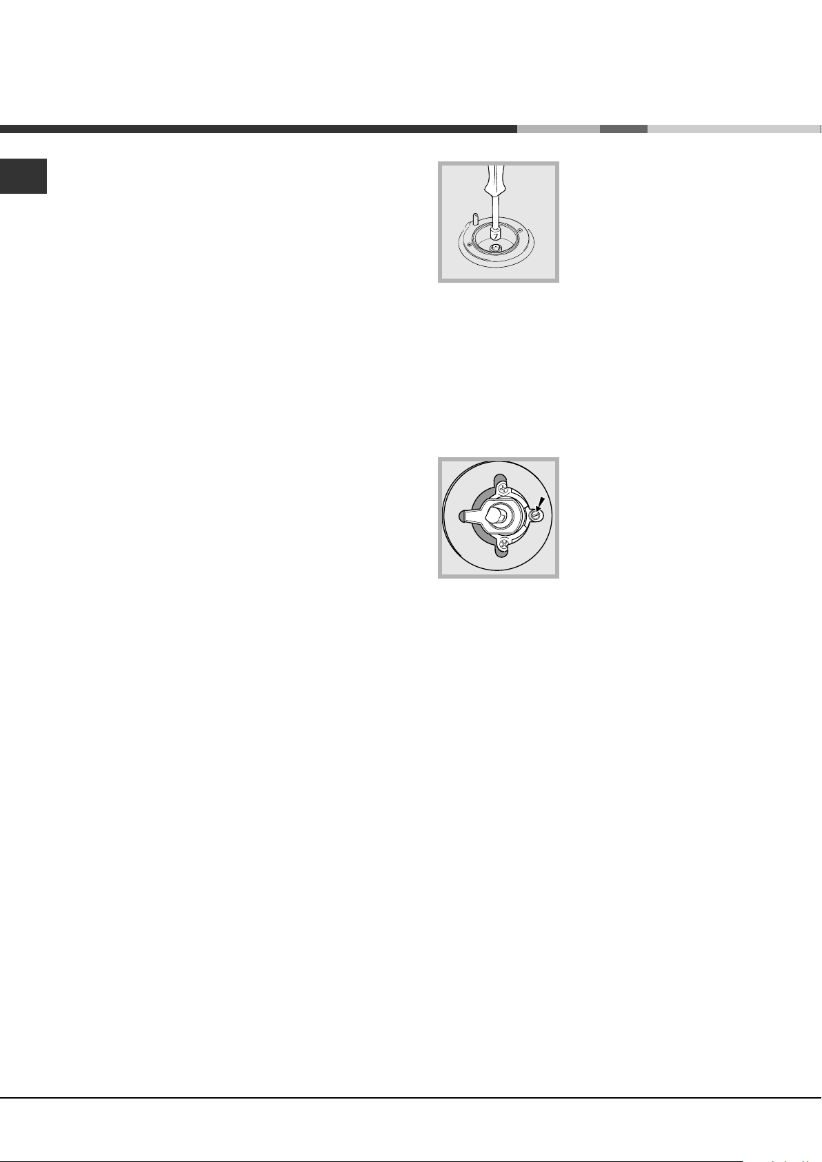
Adjusting the hob burners’
minimum setting:
1. Turn the tap to the minimum position.
2. Remove the knob and adjust the regulatory screw,
which is positioned inside or next to the tap pin, until
the flame is small but steady.
! If the appliance is connected to a liquid gas supply,
the regulatory screw must be fastened as tightly as
possible:
3. While the burner is alight, quickly change the position of
the knob from minimum to maximum and vice versa
several times, checking that the flame is not extinguished.
! The hob burners do not require primary air adjustment.
! After adjusting the appliance so it may be used with a
different type of gas, replace the old rating label with a
new one that corresponds to the new type of gas (these
labels are available from Authorised Technical Assistance
Centres).
! Should the gas pressure used be different (or vary
slightly) from the recommended pressure, a suitable
pressure regulator must be fitted to the inlet hose in
accordance with current national regulations relating
to “regulators for channelled gas”.
).
Table of burner and nozzle specifications
Adapting the hob
Replacing the nozzles for the hob burners:
1. Remove the hob grids and slide the burners off
their seats.
2. Unscrew the nozzles using a 7 mm socket
spanner (
4
see figure
), and replace them with nozzles
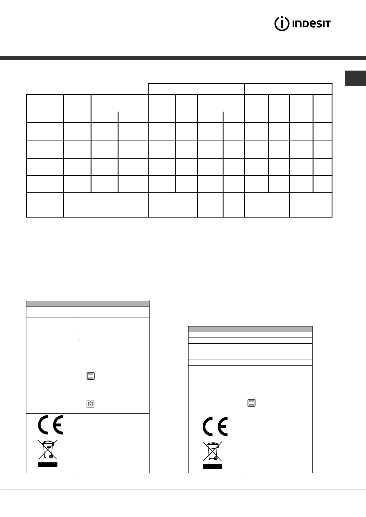
Table 1 Liquid Gas Natural Gas
GB
Burner Diameter
(mm)
Thermal Power
kW (p.c.s.*)
Nomi nal Re duc ed (mm) (mm) *** ** (mm) (mm)
Fast
(Large)(R)
Semi Fast
(Medium)(S)
Auxiliary
(Small)(A)
Tr iple Ring
(TC)
Supply
Pressures
100 3,00 0,7 41 86 218 214 116 286 143 286
75 1,90 0,4 30 70 138 136 106 181 118 181
55 1,00 0,4 30 50 73 71 79 95 80 95
130 3.25 1.5 63 91 236 232 133 309 150 309
Nominal (mbar)
Minimum (mbar )
Maximum (mbar)
* At 15°C and 1013 mbar - dry gas
** Propane P.C.S. = 50.37 MJ/kg
*** Butane P.C.S. = 49.47 MJ/kg
Natural P.C.S. = 37.78 MJ/m³
By-Pass
1/100
Nozzle
1/100
28-30
20
35
Flow*
g/h
37
25
45
Nozzle
1/100
20
17
25
Flow*
l/h
Nozzle
1/100
Flow*
l/h
13
6,5
18
TECHNICAL DATA (1st Oven )
Oven dimensions
Volume
Burners
Voltage and frequency see data plate
ENERGY LABEL
H:34;W:39;D:41 cm
54 l
may be adapted for use with any
type of gas shown on the data
plate
Directive 2002/40/EC on the
label of electric ovens.
Regulation EN 50304
Energy consumption for Natural
convection – heating mode:
Traditional mode
Declared energy consumption
for Forced convection Class –
heating mode:
Baking.
EC Directive s: 73/23/EEC
dated 19/02/73 (Low Voltage)
and subsequent amendments 89/336/EEC dated 03/05/89
(Electromagnetic Compatibility)
and subsequent amendments 90/369/EEC dated 29/06/90
(Gas) and subsequent
amendments - 93/68/EEC
dated 22/07/93 and subsequent
amendments - 2002/96/EC.
TECHNICAL DATA (2nd Oven)
;
Dimensions
Volume
Burners
Voltage and frequency see data plate
ENERGY LABEL
H:33.8;W:24.5;D:43.8 cm
36 l
may be adapted for use with any
type of gas shown on the data
plate
Directive 2002/40/EC on the
label of electric ovens .
Regulation EN 50304
Energy consumption for Natural
convectio n – heating mode:
;
Traditional mode
EC Directives: 73/23/EEC
dated 19/02/73 (Low Vol tage)
and subsequent am end m ents 89/336/EEC dated 03/05/89
(Electromagnetic Compatibility)
and subsequent am end m ents 90/369/EEC dated 29/06/90
(Gas) and subsequent
amendments - 93/68/EEC
dated 22/07/93 and subsequent
amendments - 2002/96/EC.
5
 Loading...