

Page 1

Cooker Maxioven
Instructions for installation and use
KP 59 MS(X)/G
Page 2

Cooker Maxioven
Instructions for installation and use 1
Page 3

Congratualtions on choosing an iNDESIT appliance, which you will find is dependable and easy to use. We recommend
that you read this manual for best performance and to extend the life of your appliance. Thank you.
SAFETY PRECAUTIONS
THESE INSTRUCTIONS ARE ONL Y V ALID FOR THE COUNTRIES OF DESTINA TION WHOSE SYMBOLS ARE SHOWN
IN THE BOOKLET AND THE APPLIANCE RATING PLATE.
1. This appliance has been designed for private, non-
professional use in normal dwellings.
2. Read the recommendations in this instruction
booklet carefully, as they give important advice
regarding safe installation, use and maintenance.
Keep this booklet in a safe place for further
reference when required.
3. Oven accessories which may come into contact with
food are made of materials which comply with the
contents of EEC Regulation 89/109 of 21.12.88 and
national regulations in force.
4. After having removed the packaging, check that the
appliance is intact. If in doubt, do not use the appliance
and contact professionally qualified personnel.
5. Some parts are covered with a removable scratch-proof
film. Before using the appliance the film should be
removed and the underlying part cleaned with a cloth
and a non-abrasive household cleaning product. When
switching on for the first time, it is advisable to heat the
empty oven at maximum temperature for about 30
minutes to eliminate any residue from manufacture.
6. All installation and adjustment operations should be
carried out by qualified technicians in accordance with
current regulations. Specific indications are given in the
“instructions for the installer” paragraph.
7. Before connecting the appliance, make sure that the
data on the rating plate (situated on the rear part of the
appliance and on the last page of the instruction booklet)
correspond to those of the mains electricity and gas
supplies.
8. During operation, the oven glass door and adjacent parts
of the appliance become hot. Make sure, therefore, that
children do not touch the appliance.
For greater safety, an additional child-safety device is
available from our Head Office and our Authorised
Service Centres (see enclosed list). When ordering this,
please give the code: BAB - followed by the appliance
model. The model is stamped on the plate which is
visible on the front part of the oven upon opening the
door.
9. Check that the capacity of the electrical system and
the power outlets are suitable for the maximum power
of the appliance, indicated on the rating plate. If in doubt,
consult a professionally qualified technician.
10. Periodically check the condition of the gas connection
pipe and have it replaced by a qualified technician as
soon as it shows any signs of wear or anomaly.
11. Under no circumstances should the user replace the
power supply cable or the gas connection pipe of this
appliance. In the event of damage or the necessity for
replacement, only contact an authorised service centre.
12. Do not leave the appliance plugged in if it is not in use.
Switch off the main switch and gas supply when you
are not using the cooker.
13. The burners and the cast-iron pan supports remain hot
for a long time after use. Take care not to touch them.
14. To avoid accidental spillage do not use cookware with
uneven or deformed bottoms on the burners.
15. Never use flammable liquids such as alcohol or gasoline,
etc. near the appliance when it is in use.
16. This appliance conforms to the following European
Economic Community directives:
- 73/23/EEC of 19/02/73 (Low Voltage) and subsequent
modifications;
- 89/336/EEC of 03/05/89 (Electromagnetic Compatibility)
and subsequent modifications;
- 90/396/EEC of 29/06/90 (Gas) and subsequent
modifications;
- 93/68/EEC of 22/07/93 and subsequent modifications.
1
Page 4
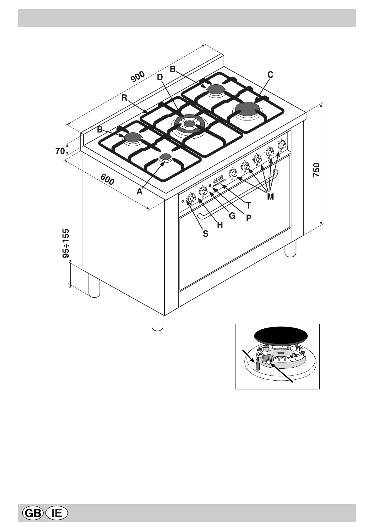
COOKER DESCRIPTION
A Auxiliary gas burner
B Semi-rapid gas burner
C Rapid gas burner
D Triple ring gas burner
R Support Grid for Cookware
M Control Knobs for Gas Burners
P Ignition Pushbutton for gas burners
E Ignitor for Gas Burners
F Safety Device - Activates if the flame accidentally goes
out (spills, drafts, etc.), interrupting the delivery of gas
to the burner.
F
E
T Minute minder
S Electric oven operation indicator light
G Electric oven selector knob (cooking function
selection)
H Electric oven thermostat knob (temperature
selection)
2
Page 5
HOB OPERATION
INSTRUCTIONS FOR USE
When a liquid starts boiling, it is advisable to turn the flame
down just enough to keep the liquid simmering.
The burners are fitted with automatic ignition and a
thermocouple safety device, which automatically cuts off
the gas from the burner in a few seconds if the flame
accidentally goes out during operation.
The burners differ in size and power. Choose the most
appropriate one for the diameter of the cookware being
used. Each burner can be regulated with the corresonding
control knob "M" by using one of the following settings:
Off
High flame
Low flame
The symbols near the knobs show the position of the
relative burner on the hob.
To ignite a burner, proceed as follows:
• turn the relative knob counter-clockwise until the pointer
is on the high-flame symbol;
• press the knob down fully and activate the automatic gas
ignition by pushing at the same time the button "P" marked
with the symbol ;
• keep the knob pressed down for about 10 seconds with
the flame lit to allow the safety thermocouple to be heated;
• release the knob, checking that the flame is stable. If it is
not, repeat the operation.
For minimum power, turn the knob towards the low flame
symbol. Intermediate positions are possible by simply putting
the knob anywhere between the high and the low flame
symbol. To turn off the burner, turn the knob clockwise to
the off position " " .
Important:
• Do not activate the automatic ignition device for more
than 15 consecutive seconds.
• Difficulty in ignition is sometimes due to air inside the
gas duct.
• If a burner flame accidentally goes out, the gas continues
to exit for a few moments before the safety device
activates. Turn the control knob to the off position and do
not attempt ignition again for at least 1 minute, thereby
letting the gas disperse, which could otherwise be a
danger.
• When the appliance is not in operation, check that the
knobs are in the off position " " . The main gas supply
cut-off cock should also be closed.
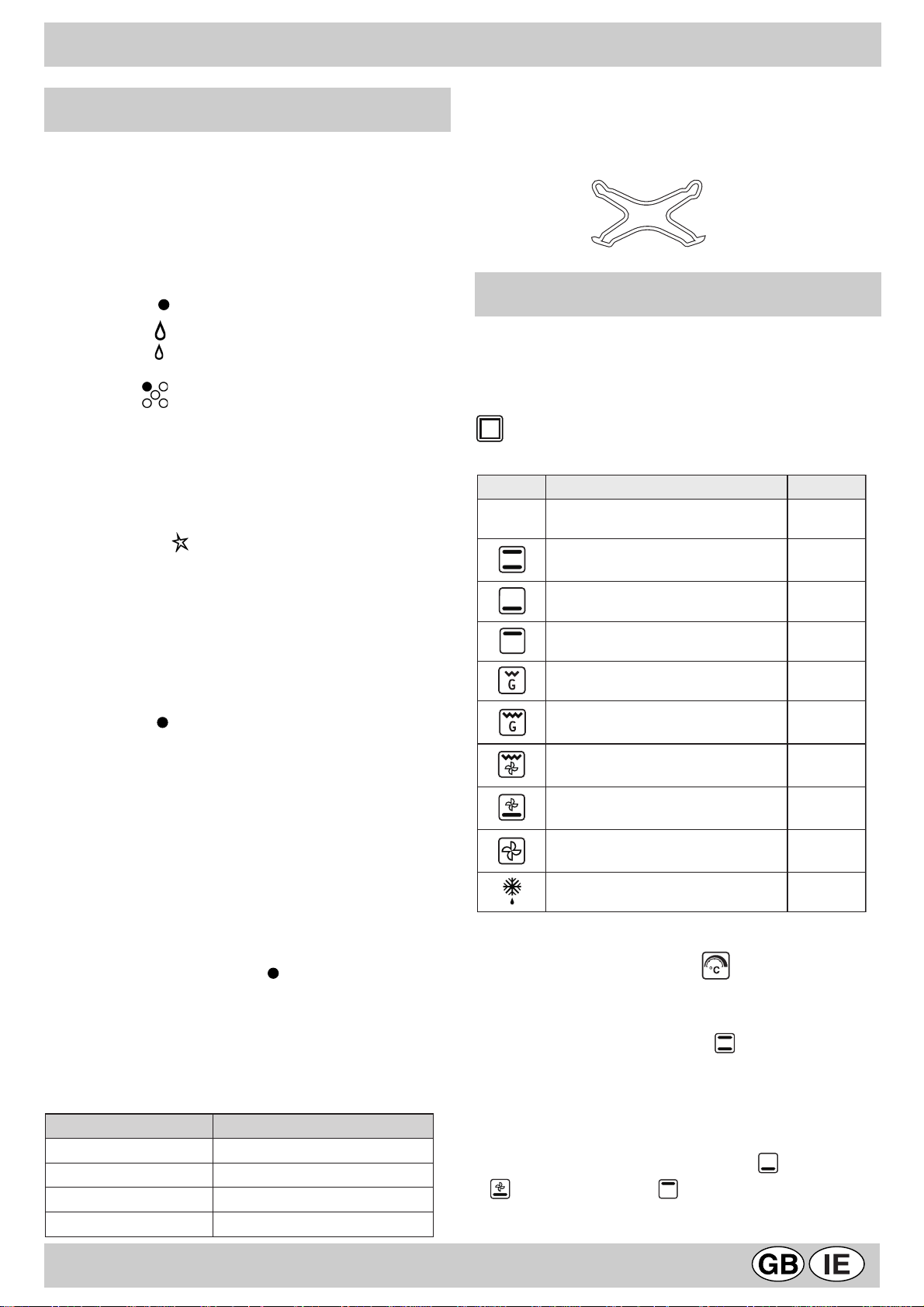
The hob is fitted with a pan reducing support (fig.1), which
should only be used on the auxiliary burner "A"
fig.1
MULTI-FUNCTION OVEN
The oven offers nine combinations of heating elements; so
the most suitable combination may therefore be chosen for
each dish, with convincing results.
By turning the selector knob “G” marked with the symbol
, different cooking modes are obtained, as shown in
the following table:
lobmyS noitcnuF rewoP
0
After having selected the heat source, put the thermostat
knob "H" (marked with the symbol ) onto the temperature
required.
ffO)0-
gnitaehmottoB+poT)1
stnemele
tnemelegnitaehmottoB)2W0031
tnemelegnitaehpoT)3W0501
tnemelegnitaehllirG)4W0002
gnitaehllirG+poT(llirgixaM)5
)stnemele
gnitaehllirG+poT(llirgixaM)6
naf+)stnemele
tnemelegnitaehmottoB)7
naF+
tnemelegnitaehdnuorraeR)8
naF+
gnitsorfedtsaF)9W05
W0532
W0503
W0503
W0031
W0082
Using the burners
To obtain maximum efficiency from the burners, it is
advisable to only use pans with a diameter suitable for the
burner being used, so that the flame does not extend beyond
the pan base (see following table).
renruB .mcninapehtforetemaiD
AyrailixuA41ot6morf
Bdipar-imeS02ot51morf
CdipaR03ot12morf
DgnirelpirT03ot42morf
• For traditional cooking (roasts, biscuits, etc.) in
conventional
below).
Only put the food to be cooked into the oven when it has
reached the selected temperature and preferably use just
one shelf for cooking.
To provide heat only to the bottom or the top part of the
dishes, turn the selector to the position (hot below) or
(hot below + fan) or (hot above);
3
mode use the mode (hot above +
Page 6

• With this (fan assisted)mode heat is transmitted to
the food through pre-heated air made to circulate inside
the oven by a fan. The oven heats up very quickly so the
food to be cooked may be put into the oven as soon as it
is switched on. Cooking is also possible simultaneously
on two shelves.
• The “fast defrosting“ function uses no heating
elements, just the oven light and the fan.
• Grill operation: a high heat output is used for grilling, so
that the surface of the food is immediately browned; this
is particularly indicated for meats which should remain
tender on the inside. To grill, turn the selector knob "G"
to one of these positions: (grill), (maxigrill),
(maxigrill + fan)
During grilling, do not set the thermostat knob to above
200 °C and keep the oven door closed.
Oven light
The oven light comes on automatically when the selector
knob is turned to any of its positions.
Indicator light "S"
(figure a on page 2) It indicates that the oven is heating up.
When the light goes out, the required temperature has been
reached inside the oven.
When the light alternately comes on and goes out, it means
that the thermostat is working properly to maintain the oven
temperature.
Minute minder "T"
This is a buzzer timer situated on the control panel and is
suitable for timing up to a max. of 60 minutes.
Turn the knob with the symbol until the pointer is aligned
with the required time. When the set time has elapsed, a
buzzer sounds (it does not turn the oven off).
It is advisable to turn the knob to 60 and then back to the
time required, even if this is less than 60 minutes.
See pages 5-6 for the cooking times and temperatures
required for different foods.
Spit - Rotisserie
Insert the meat to be cooked along the length of the spit
rod, securing it with the special adjustable forks (fig. 2).
Introduce the supports “A” and “B” (fig. 3) into the holes in
the drip tray “E”, rest the rod groove on the seat “C” and
insert the oven rack into the lowest guide of the oven; now
insert the spit rod into the relative hole, moving the groove
forward into seat “D” . Start the rotisserie by turning the
selector knob to one of the following positions:
CLEANING AND MAINTENANCE
To ensure a long life cycle for the appliance, it is essential
to carry out a thorough general clean frequently, taking into
account that:
The appliance should be disconnected from the mains
supply before starting cleaning operations.
Avoid cleaning appliance parts when they are still warm.
The enamelled, chromed or glass parts must be washed
with warm water without using abrasive powders or
corrosive substances which could ruin them.
The inside of the oven should be cleaned every time it is
used with hot water and detergent; rinse and dry
thoroughly.
The steel parts and especially the areas with the screen-
printed symbols should not be cleaned with diluents or
abrasive detergents. It is advisable to use only a a damp
cloth with tepid water and washing up liquid. After cleaning,
the surfaces should be rinsed thoroughly with water and
then dried well.
Avoid leaving acidy liquids (vinegar, lemon juice,
aggressive detergents, etc.) on enamelled or varnished
parts.
The removable parts of the burners on the hob should be
washed frequently with warm water and soap, making sure
to remove any caked-on substances. Check that the gas
outlet slits are not clogged. Dry the burners carefully
before using them again.
Clean the end part of the automatic glow plug ignitors of
the hob frequently.
Greasing the taps
As time passes, a tap may lock or become difficult to turn.
In this case it will be necessary to clean inside and replace
the grease. This procedure must be performed by a
technician authorized by the manufacturer.
Changing the oven lightbulb
Make sure that the appliance is disconnected from the
electricity supply.
Unscrew the glass protective cover from inside the oven,
unscrew the lightbulb and replace it with an identical one
suitable for high temperatures (300°C) and with the following
characteristics:
- Voltage 230 V
- Wattage 15 W
- T ype E 14.
fig.2
fig.3
4
Page 7

COOKING PROGRAMMER
The electronic programmer has the function of
automatically switching on the oven (at the required time)
and switching it off at the end of the set cooking time. The
4 figure luminous display showing the actual time and the
programming times, also shows the current state of the
oven by means of the following symbols:
Oven on
Minute minder
Automatic programme AUTO
Point (this divides the hour from the minutes on the
display)
All the functions may be programmed for a total of 23 h
and 59 min. Maximum cooking time is 10 hours.
Adjusting the clock
(At installation, after power failures, clock in advance or
behind).
Select manual mode by pressing key , adjust the hour
and minutes using the and keys.
Manual oven mode (Programming excluded)
Press the key ; and the oven is switched on, the AUTO
symbol goes out and the (oven on) symbol comes on.
This operation erases any set programme.
Semi-automatic oven mode
1st example: start in manual cooking mode - programmed
cooking time.
l Put the food to be cooked in the oven.
l Press the key (duration) and adjust the cooking
time using the and keys: the oven switches on,
the AUTO and (oven on) symbols light up.
l Turn the selector and the thermostat knobs onto the
required function and temperature respectively.
l At the end of the set cooking time, the oven is
automatically switched off, the symbol (oven on) goes
out and the AUTO symbol blinks; an acoustic signal
sounds.
2nd example: start with manual cooking mode - end with
programmed cooking mode.
l Put the food to be cooked in the oven.
l Press the key (end of cooking) and adjust the end
of cooking time using the and keys: the oven
switches on, the AUTO and symbols light up.
l Turn the selector and the thermostat knobs onto the
required function and temperature respectively.
l At the end of cooking, the oven is automatically switched
off, the symbol (oven on) goes out and the AUTO
symbol blinks; an acoustic signal sounds.
goes out (the oven switches off).
l Turn the selector and the thermostat knobs onto the
required function and temperature respectively.
l The programmer automatically sets the start of cooking
time, which is shown by the symbol (oven on) coming
on. When the cooking time has elapsed, the oven is
automatically switched off, the (oven on) symbol goes
out and the AUTO symbol blinks; an acoustic signal
sounds.
Minute minder
Press the key (minute minder) and set the time required
using the and keys. An acoustic signal sounds at the
end of the programme.
Buzzer
The buzzer emits a sound for 7 minutes after the end of the
selected programme; it may be stopped by pressing any
function key. It is possible to choose 3 different types of
acoustic signal. By pressing the key the actual signal
tone appears. Now, within 7 seconds, every further press
of the key changes the signal tone.
Programme control
Press the key for the remaining time to be displayed,
and the key to check the end of cooking time.
Erasing programmes
Once a programme has been carried out, it is automatically
erased; it can also be cancelled by pressing the key
(manual).
Automatic oven mode (programmed cooking duration and
end)
l Put the food to be cooked in the oven.
l Press the key (Duration) and adjust the cooking
time using the and keys: the AUTO and (oven
on) symbols light up (the oven switches on).
l Press the key (end of cooking) and adjust the end
of cooking time using the and keys: the symbol
5
Page 8

COOKING TIPS
Cooking times may change according to the nature of the foods, their homogeneity and their volume. When cooking a
certain food for the first time, it is advisable to choose the lowest values in the cooking time range given in the table and
then increase them if necessary.
CONVENTIONAL oven cooking
hsidfoepyT
erutarepmeT
C°
sekacdnaseirtsaP
eiptiurF
seugnireM
ekacegnopS
ekaclegnA
ekacariedaM
ekacetalocohC
faolteewstalF
sffuP
stiucsibyrtsapykalF
selliuefelliM
yrtsaptrohS
031
031
051
061
061
071
071
002
002
002
002
hsidfoepyT
).gk5.0(spohC
segasuaS
)gk1(nekcihcdellirG
).gk6.0(tipsehtnolaeV
emitgnikooC
)setunim(
07-06
04-03
03-02
05-04
05-04
04-03
05-04
02-51
02-51
02-51
02-51
GRILLING
).gk1(tipsehtnonekcihC
hsidfoepyT
taeM
).gk8-4(yekruT
).gk5-4(esooG
).gk4-2(kcuD
).gk3-½2(nopaC
feebdesiarB).gk½1-1(
bmalfogeL
).gk2(erahtsaoR
tnasaehptsaoR
).gk½1-1(nekcihC
hsiF
emitgnikooC
)setunim(
06
51
06
06
06
erutarepmeT
C°
061
061
071
071
061
061
061
061
071
002
flehsfonoitisoP
liarediugdr3
liarediugdn2
liarediugts1
-
The 1st guide rail is
understood as being
the lowest position.
-
emitgnikooC
)sruoh(
½4-3
½4-4
½2-½1
½2-2
½3-3
½1-1
½1-1
½1-1
½1-1
setunim52-51
FAN ASSISTED cooking
hsidfoepyT
sekacdnaseirtsaP
dluomni,ximnetaebhtiW*
esabnalf,yrtsaptrohS
taeM
laeV
feeB
kroP
nekcihC
laeV
feeB
kroP
nekcihC
kcuD
hsiF
sretsyO
selabmiT
gnitsorfeD
taeM
taeM
taeM
Notes:
1) Cooking times do not include oven pre-heating, except for those marked with an asterisk
2) The indication given in the table for the guide rails is the one that should preferably be used in the event of cooking on more than one level.
3) The indicated times refer to cooking on one shelf only; for cooking on more than one level, increase the time by 5 ÷ 10 min.
4) For roast beef, veal, pork and turkey, on the bone or rolled, increase the times by 20 min.
llirgrednustsaoR
feebtsaorhsilgnE
yartnostsaoR
secilsyekruT
seloressaC
feebdesiarB
laevdesiarB
hsidatsapdekaB
gniddupelbategeV
sehciwdnasdetsaoT
sehsidtae-ot-ydaeR
nomlas,tobrut,lerekcaM
dluomtuohtiw,ximnetaebhtiW*
gnilliftewhtiwyrtsaptrohS
gnillifyrdhtiwyrtsaptrohS
ximdenevaellarutanhtiW*
sekacdnaseirtsapllamS
elos,ekahdoc,skaets,stelliF
sélffuosyruovasdnateewS*
lloryruovasdnasazziP*
.oNliarediuG
mottobmorf
3-1
4-3-1
4-3-1
3-1
4-3-1
3-1
4-3-1
2
2
2
2
2
3-1
3-1
3-1
3-1
3-1
3-1
1
1
3-1
3.1
3-1
3-1
3-1
3-1
4-3-1
4-3-1
3-1
3-1
3-1
3-1
ytitnauQ
.gk
1
1
5.0
5.1
1
1
5.0
1
1
1
1
5.1-1
1
1
1
5.1-1
5.1
5.1-1
1
1
1
1
2
2
57.0
5.0
5.0
1
5.0
57.0
1
erutarepmeT
C°
571
571
571
571
571
571
061
081
081
022
081
002
061
061
061
081
081
081
571
571
081
081
081
581
581
081
002
091
002
05
05
05
emiT
)setunim(
06
05
03
07
54
05
03
06
07
05
07
07
08
09
09
09
021
021
021
011
03
54
02
06
05
05
03
51
54
05
07
011
6
Page 9

INSTALLATION
In a chimney stack or branched flue Directly to the outside
(exclusively for cooking appliances)
fig.6
fig.4
The following instructions are provided for qualified installers
so that they may accomplish installation, adjustment and
technical maintenance operations correctly and in
compliance with current regulations and standards.
Important: the appliance should be disconnected from
the mains electricity supply before any adjustment,
maintenance, etc. is carried out. Maximum caution should
be used should it be necessary to keep the appliance
connected to the electricity supply.
The cookers have the following technical specifications:
Category: II 2H3+ Class: 1 Type: Y
The dimensions of the appliance are given in the figure on
page 2.
For trouble-free operation of appliances installed in housing
units, the minimum distances shown in fig.4 should be
observed. Adjacent surfaces and the wall at the rear should
also be able to withstand an overheating temperature of 65
°C.
Prior to installing the cooker, 95 ÷ 155 mm high supporting
feet (provided) should be fitted into the holes to be found in
the bottom of the cooker (fig.5). These feet are screwadjustable and whenever necessary should be used to make
sure the cooker stands level.
Kitchen ventilation
The air flow into the room where the appliance is installed
must equal the quantity of air that is required for regular
combustion of the gas and for ventilating the same room.
Air must be taken in naturally through permanent apertures
made in the outside walls of the room or through single or
branching collective ventilation ducts in compliance with
current standards and regulations.
The air must be taken directly from the outside, from an
area far from sources of pollution.
The ventilation aperture must have the following
characteristics (fig.7A):
total free cross section of passage of at least 6 cm² for
every kW of rated heating capacity of the appliance, with
a minimum of 100 cm² (the heating capacity is indicated
on the rating plate);
it must be made in such a way that the aperture, both on
the inside and outside of the wall, cannot be obstructed;
it must be protected, e.g. with grates, wire mesh, etc. in
such a way that the above-mentioned free section is not
reduced;
it must be situated as near to floor level as possible.
Detail A Adjacent Room to be
room ventilated
fig.5
Positioning
This appliance may only be installed and operated in
permanently ventilated rooms in compliance with current
standards. The following requirements must be observed:
The appliance must discharge combustion products into
a special hood, which must be connected to a chimney,
flue pipe or directly to the outside (fig.6).
If it is impossible to fit a hood, the use of an electric fan is
permitted, either installed on a window or on an external
wall, which must be switched on at the same time as the
appliance.
A
Examples of ventilation holes Enlarging the ventilation slot
for comburant air between window and floor
fig. 7A fig. 7B
The air inflow may also be obtained from an adjoining room,
provided the latter is not a bedroom or a room where there
is a risk of fire, such as warehouses, garages, fuel stores,
etc. and is ventilated in compliance with the current
standards and regulations.
Air from the adjoining room to the one to be ventilated may
be made to pass freely through permanent apertures with
a cross section at least equal to that indicated above. These
apertures may also be obtained by increasing the gap
between the door and the floor (fig.7B).
7
Page 10

If an electric fan is used for extracting the combustion
products, the ventilation aperture must be increased in
relation to its maximum performance. The electric fan should
have a sufficient capacity to guarantee an hourly exchange
of air equal to 3 ÷ 5 times the volume of the kitchen.
Prolonged, intensive use of the appliance may require extra
ventilation, e.g. an open window or a more efficient
ventilation system by increasing the extraction power of
the electric fan if installed.
Liquid petroleum gas descends towards the floor as it is
heavier than air. Apertures in the outside walls in rooms
containing LPG cylinders should therefore be at floor level,
in order to allow any gas from leaks to be expelled. Do not
store LPG cylinders (even when empty) in basements or
rooms below ground level; it is advisable to keep only the
cylinder in use in the room at any one time and connected
far from heat sources which could raise its temperature to
above 50 °C.
Gas supply connection
• Check that the appliance is set for the type of gas available
and then connect it to the mains gas piping or the gas
cylinder in compliance with current regulations and
standards.
• This appliance is designed and set to work with the gas
indicated on the label situated on the actual hob. If the
gas supply is other than the type for which the appliance
has been set, proceed with replacing the corresponding
nozzles (provided), following instructions given in the
paragraph “Adaptation to different types of gas”.
• For trouble-free operation, suitable use of energy and
longer life of the appliance, make sure that the supply
pressure complies with the values indicated in the table 1
"burners and nozzles specifications, otherwise install a
special pressure regulator on the supply pipe in
compliance with current standards and regulations.
• Connect in such a way that the appliance is subjected to
no strain whatsoever.
Either a rigid metal pipe with fittings in compliance with the
standards in force must be used for connecting to the nipple
union (threaded ½"G male fitting) situated at the rear of the
appliance to the right (fig.8), or flexible steel pipe in
compliance with the standards in force, which must not
exceed 2000 mm in length.
Should it be necessary to turn the fitting, the gasket (supplied
with the appliance) must be replaced.
Upon completion of installation, check the gas circuit, the
internal connections and the taps for leaks using a soapy
solution (never a flame).
Also check that the connecting pipe cannot come into contact
with moving parts which could damage or crush it.
Make sure that the natural gas pipe is adequate for a sufficient
supply to the appliance when all the burners are lit
Important: A pressure regulator, in compliance with the
standards in force, must be inserted when connecting to a
liquid gas supply (in a cylinder).
A
fig.9
Adaptation to a different type of gas
If the appliance is to be converted for use with a type of
gas other than that for which it was set in the factory
(indicated on the label to be found on the hob), the burner
nozzles should be replaced as follows:
• remove the grids and the burners.
• Unscrew the nozzles "A" (fig.9), using a 7 mm socket
wrench and replace them, according to the table 1
"burners and nozzles specifications", with ones suitable
for the new type of gas.
• On completing the operation, replace the old rating label
with the one showing the new type of gas; the sticker is
available from our Service Centres.
• Re-assemble all the components.
fig.8
8
Page 11

Adjusting the low flame
• Put the tap to the low flame position (the burner should
be lit);
• Remove the tap knob and turn the adjusting screw,
situated to the side of the tap stem (fig.10) until you
obtain a regular small flame, using a screwdriver
(loosening the screw increases the height of the flame,
tightening decreases it).
N.B. : the adjusting screw must be fully screwed down
for liquid gas.
• Having obtained the low flame setting required and with
the burner lit, abruptly change the position of the knob
several times from minimum to maximum and vice versa and check that the flame does not go out.
• Refit the tap knobs
fig.10
ELECTRICAL CONNECTION
THE APPLIANCE MUST BE EARTHED
The appliance is designed to work with alternating current
at the supply voltage and frequency indicated on the rating
plate (situated on the rear part of the appliance and on the
last page of the instruction booklet). Make sure that the
local supply voltage corresponds to the voltage indicated
on the rating plate.
Connecting the supply cable to the mains electricity
supply
For models supplied without a plug, fit a standard plug,
suitable for the load indicated on the rating plate, onto the
cable and connect it to a suitable socket.
T o connect directly to the mains supply, an omnipolar switch
with a contact break of at least 3 mm suitable for the load
and complying with current standards and regulations must
be fitted between the appliance and the mains supply outlet.
The yellow-green earth wire must not be interrupted by the
switch.
The supply cable must be in such a position that no part of
it can reach a temperature of 50 °C above room temperature.
All the appliances should be connected seperately.
Do not use adapters or shunts as they could cause heating
or burning.
Before connecting to the power supply, make sure that:
• the limiter valve and the domestic system can withstand
the load from the appliance (see rating plate);
• the supply system is efficiently earthed according to the
standards and laws in force;
• the socket or omnipolar switch are easily accessible when
the appliance is installed.
FAILURE TO OBSERVE THE ACCIDENT-PREVENTION
REGULATIONS RELIEVES THE MANUFACTURER OF ALL
LIABILITY .
Replacing the cable
Use a rubber cable of the type H05VV-F with a suitable
cross section of 3 x 1.5 mm².
The yellow-green earth wire must be 2 ÷ 3 cm longer than
the other wires.
9
Page 12

BURNER AND NOZZLE SPECIFICATIONS
1elbaTsagdiuqiLsaglarutaN
renruBretemaiD
)mm(
rewoplamrehT
)*.s.H(Wk
ssap-yB
001/1
elzzoN
001/1
*wolF
h/g
elzzoN
001/1
*wolF
h/l
.nimoN.cudeR03G73G02G
)mm(
)mm(
)mm(
CdipaR00100.37.00468812412611682
Bdipar-imeS5756.14.0034602181169751
AyrailixuA5500.13.0720537171759
DgnirelpirT03152.33.17519632232421903
erusserpylppuS037302
* At 15°C and 1013 mbar-dry gas
Propane G31 H.s. = 50,37 MJ/kg
Butane G30 H.s. = 49,47 MJ/kg
Methane G20 H.s. = 37,78 MJ/m
3
TROUBLESHOOTING
Sometimes, the appliance could not function properly or at
all. Before calling customer services for assistance, let's
see what can be done.
First of all, check to see that there are no interruptions in
the gas and electrical supplies, and, in particular, that the
gas valves for the mains are open.
The burner does not light or the flame is not uniform
around the burner.
Check to make sure that:
l The gas holes on the burner are not clogged.
l All the movable parts that make up the burner are
mounted correctly.
l There are no draughts around the appliance.
The flame does not stay lit.
Check to make sure that:
l You press the knob all the way in.
l You keep the knob pressed in long enough to activate
the safety device.
l The gas holes are not clogged in the area corresponding
to the safety device.
The burner does not remain on when set to "Low".
Check to make sure that:
l The gas holes are not clogged.
l There are no draughts near the appliance.
l The minimum flame has been adjusted correctly (see
the section entitled, "Adjusting the low flame").
The cookware is not stable.
Check to make sure that:
l The bottom of the cookware is perfectly flat.
l The cookware is centered correctly on the burner.
If, despite all these checks, the hob does not function
properly and the problem persists, call the nearest Merloni
Elettrodomestici Customer Service Centre, informing them
of the following information:
- The type of problem.
- The abbreviation used to identify the model (Mod. ...) as
indicated on the warranty.
Never call upon technicians not authorized by the
manufacturer, and always refuse to accept spare parts that
are not original.
10
Page 13

Page 14

Page 15

Page 16

Merloni Elettrodomestici
Viale Aristide Merloni 47
60044 Fabriano
Italy
Tel +39 0732 6611
Fax +39 0732 662501
www .merloni.com
Cucina Maxiforno " KP 59 MS (X) /G"
02/01 - 195030285.00Xerox Business Services - Docutech
 Loading...