

INDESIT IDVA 735 X (AUS) User Manual
Instruction manual
TUMBLE DRYER
EN
English, 1
IDVA 735X
Contents
Installation, 2-3
Where to install the tumble dryer
Ventilation
Electrical connections
Levelling the tumble dryer
Before you start your dryer
Description of the tumble dryer, 4-5
Front side
Rear side
Control panel
How to carry out a drying cycle, 6
Starting and selecting a programme
Programmes and options, 7-8-9
Programme chart
Special programmes
Options
Opening the door
Laundry, 10-11
Sorting laundry
Care labels
Special items
Drying times
EN
! This symbol reminds you to read this instruction manual.
! Keep this manual at hand for immediate reference whenever
necessary. Always store this manual close to the tumble dryer and
remember to pass it on to any new owners when selling or tran-
sferring the appliance, so they may familiarise with the warnings
and suggestions herein contained.
! Read these instructions carefully: the following pages contain
important information on installation and useful suggestions for
operating the appliance.
Warnings and suggestions, 12
General safety
Saving energy and respecting the environment
Care and maintenance, 13
Disconnecting the power supply
Cleaning the filter after each cycle
Checking the drum after each cycle
Cleaning the tumble dryer
Troubleshooting, 14
Assistance and Guarantee, 15-16-17
Spare parts
Information on recycling and disposal
1
Installation
m
B
A
EN
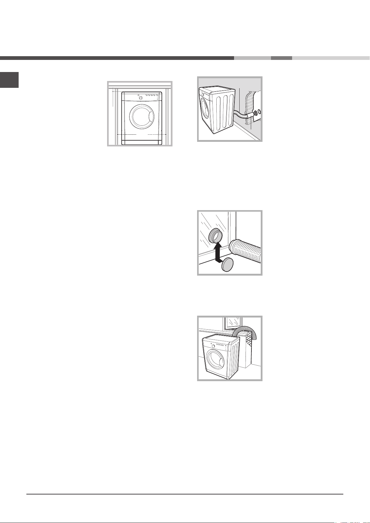
Where to install the tumble dryer
• Install the dryer far from gas
ranges, stoves, radiators or hobs,
as flames may damage it.
If the dryer is installed below a
worktop, ensure there are 10 mm
between the upper panel of the
dryer and any objects above it,
and 15 mm between the sides
of the machine and the walls or
furniture units adjacent to it. This
ensures adequate air circulation.
Make sure the air inlets on the rear panel are not blocked or
obstructed.
• You should also make sure that the room in which
the tumble dryer is installed is not damp, and that it is
adequately ventilated.
Ventilation
This appliance gently dries laundry by taking in COOL, clean
and relatively dry air, heating it and passing it through the
fabric. To facilitate the drying process, damp air is expelled at
the rear, through a ventilation hose. When the dryer is in use,
there has to be adequate ventilation to avoid a back flow
of gases into the room from appliances burning other fuels,
including open fires.
! We do not recommend that the dryer is installed in a
cupboard because dangerous levels of heat can build up. !
The appliance must not be installed behind a lockable door,
a sliding door or a door with a hinge on the opposite side to
that of the tumble dryer in such a way that a full opening of
the tumble dryer door is restricted.
Wall ventilation hole
1. Leave an opening in the wall
to the left of the tumble dryer
installation site.
2. Make the hose as short and
straight as possible, in order
to prevent any moisture from
condensing and leaking back
into the appliance.
3. The hole in the wall must
also be straight and pointing
downwards, so that the flow of air coming out is not
impeded.
Areas A and B should be checked frequently, to prevent
the accumulation of fluff or debris, particularly if the tumble
dryer is used very often. The hose adaptor must be fitted
correctly, in order to prevent damp air from coming back into
the room.
Window ventilation hole
The ventilation hole should
be directly behind the dryer in
order to keep the hose as short
as possible.
! Make sure you do not
push the tumble dryer too
far backwards, as this could
lead to the ventilation hose
being crushed, bent or even
disconnected.
! There should be no cuts, kinks or “U”-shaped bends
in the hose, as these could impede ventilation or trap
condensation.
Mobile ventilation system
When using the tumble dryer with the mobile ventilation
system, a ventilation hose must be connected. The hose
should be securely fastened to the ventilation hole at the
rear of the appliance (see “Description of the tumble dryer”).
We recommend the hose is connected to an outlet near
the tumble dryer, if possible. If it cannot be installed in a
permanent spot, the tumble dryer will still function perfectly
well if the ventilation hose is passed through a partiallyopened window.
! Make sure you do not point the ventilation hose towards
the air inlet, which is located on the rear of the appliance.
! The ventilation hose should not exceed a maximum length
of 2.4 metres; it should also be shaken frequently to remove
any fluff, dust or water deposits inside it. Make sure you do
not crush the hose.
Fixed ventilation system
We recommend the ventilation hose is connected to a
ventilation system for windows or doors, available from the
retailer which originally sold you the appliance or from your
local spare parts stockist.
Ventilation through an open window
The end of the hose must be
facing downwards, in order to
prevent the hot, damp air from
forming condensation in the
room or the tumble dryer.
! Make sure that the tumble dryer is adequately ventilated,
and that the end of the ventilation hose is not pointing
towards the air inlet pipe on the rear of the appliance.
! The ventilation hose must always be fitted to ensure
optimum performance.
! Make sure that the ventilation hose and the air inlet vents
are not obstructed or blocked.
! Do not let the tumble dryer recirculate exhaust air.
! Improper use of the tumble dryer may result in fire hazards.
! The air emitted by the tumble dryer must not be expelled in
the same duct as used for the fumes produced by different
appliances which burn gas or other fuels.
! Do not discharge the exhaust air into an extraction system
or any duct with an extractor fan. This will affect the way the
thermal controls operate and can result in a fire hazard.
2
Electrical connections
Before plugging the appliance into the socket, check the
following:
• Make sure your hands are dry.
• The socket must have an earth connection.
• The socket must be able to withstand the machine’s
maximum power output as indicated on the data plate (see
Description of the tumble dryer).
• The power supply voltage must fall within the values indicated on the data plate (see Description of the tumble dryer).
• The socket must be compatible with the dryer’s plug.
Should this not be the case, replace the plug or the socket.
! Do not use extension cords.
! The dryer must not be installed outdoors, even if the space
is sheltered. It can be very dangerous if exposed to rain or
storms.
! Once installed, the dryer’s electrical wire and plug must be
within reach.
! The power cord must not be bent or squashed.
! If the plug being replaced is a non-rewirable type, then
the cut-off plug must be disposed of safely. DO NOT leave
it where it can be inserted into a socket and create a shock
hazard.
! The power cord should be checked periodically and
replaced by a cord specially prepared for this dryer and fitted
only by authorized technicians (see Service). New or longer
power cords are supplied at an extra charge by authorized
dealers.
! Ensure that any portable outlet or extension lead is positioned so that it is not subjected to any splashing or ingress of
moistures
! The manufacturer denies any responsibility should any of
these rules not be followed.
! If in doubt about any of the above consult a qualified
electrician.
Before you start your dryer
Once the tumble dryer is installed, clean the inside of the
drum before operating it and remove any dirt accumulated
during transportation.
EN
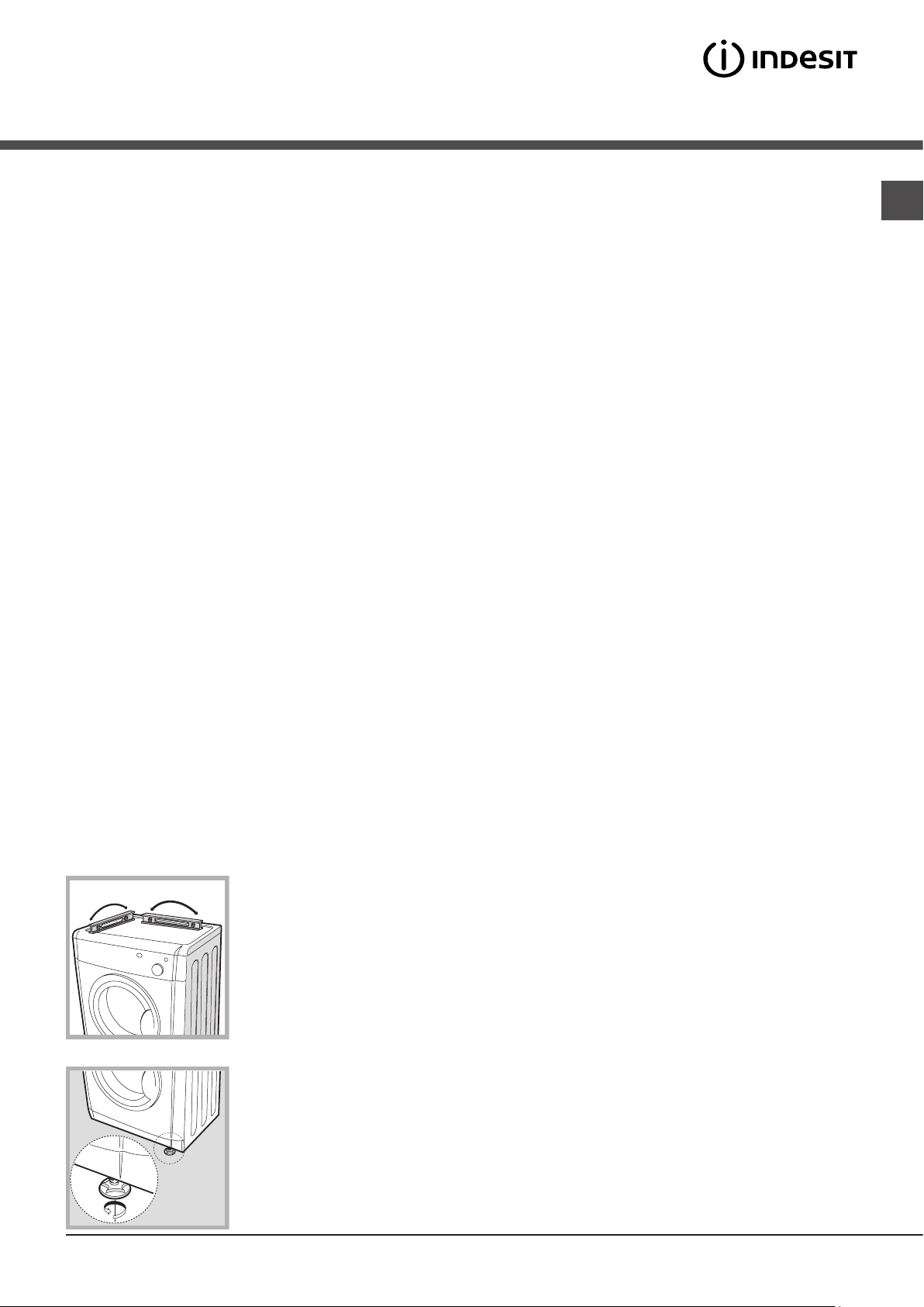
Levelling the tumble dryer
The tumble dryer should be installed level in order to
operate correctly.
After installing the tumble
dryer in its permanent
position, make sure it is level;
check its side-to-side levelling
first, followed by front-toback.
If the tumble dryer is not
perfectly level, use a wooden
block to support it while you
adjust the two front feet, up or
down as necessary.
3
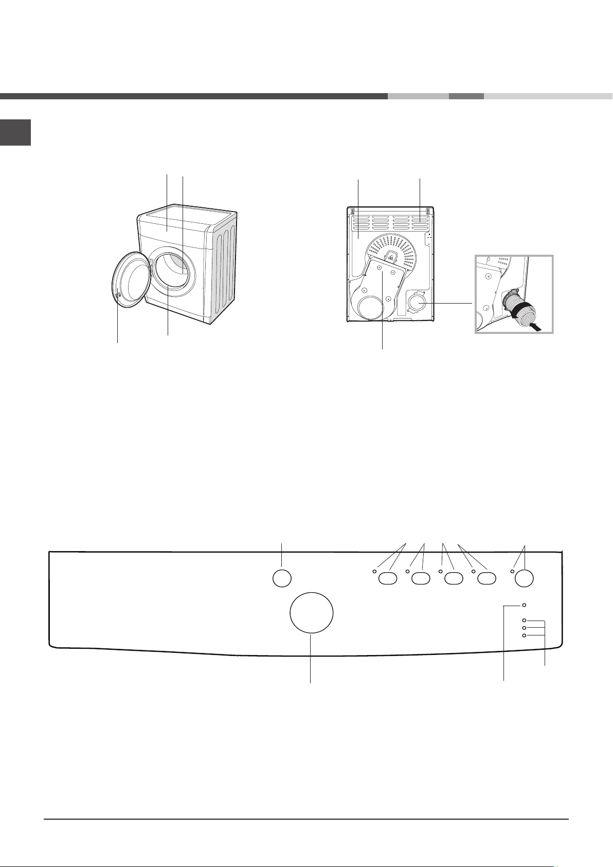
Description of
the tumble dryer
Front side Rear side
EN
Control panel
Serial number
and model
number
Filter
Drum
Rating Plate
Caution, high
temperature
Air inlet
Connection for
ventilation hose
Control panel
On/Off
button
Programme
selection knob
Options
buttons and
indicator lights
Start/Pause button
and indicator light
Clean filter
indicator light
Drying phase
or delayed start
indicator lights
4
ON/OFF/Reset button
Pressing the button normally will cause the machine to switch on or off. If the button is pressed for 3 seconds while the dryer is in
function, the machine will switch off and the running cycle will reset.
Programme selection knob
Allows for setting the programme: turn until the indicator points towards the desired programme (see Starting and selecting a
programme).
Options buttons
Allow for selecting the options available for the selected programme. The relative indicator lights turn on when the option has been
selected (see Programmes and options).
START/PAUSE button and indicator light
When the green light flashes slowly, press the button to start the programme. When the cycle is under way, the indicator light remains
on. To put the programme into pause mode, press the button again; the indicator light will turn orange and start flashing again.
To resume the programme from the point it was interrupted, press the button again (see Start and programme selection).
Indicator lights
The indicator lights provide important information. They indicate the following:
“Clean filter” indicator light
Before each programme, the “Clean filter” indicator light signals that it is essential to clean the filter each time before using the
tumble dryer (see Care and maintenance).
EN
“Drying phases” indicator lights
The indicator light signals that the drying phase is running.
The indicator light signals that the cooling phase is running.
The END indicator light signals that the programme has ended.
“Delay start” indicator light
If the ”Delay start” option has been activated (see “Programmes and options”), after the programme has started, the indicator light
corresponding to the chosen delay time will start flashing:
As time passes, the remaining delay will be displayed and the corresponding indicator light will flash:
Once the set delay time ends, the flashing LED will turn off and the set programme will start.
5
 Loading...