

INDESIT I5GMH6AG(A) U User Manual

I5TMH6AG U
I5GMH6AG.1 U
I5GMH6AG U
I5TMH5AG.1 U
I5GMH2AG U
I5GMH5AG U
I5GMHA U
I5GMH1A U
I5GMH5AG U
I5GMH6AG U
English
GB
English
LV
Latviešu
Latviešu
Operating Instructions
COOKER AND OVEN
Contents
Operating Instructions,1
WARNING
Description of the appliance-Overall view,5
Description of the appliance-Control Panel,6
Installation,7
Start-up and use,12
Cooking modes,13
Precautions and tips,19
Care and maintenance,20
Assistance,20
PL
Instrukcja obsługi
Instrukcja obsługi
KUCHENKA I PIEKARNIK
KUCHENKA I PIEKARNIK
Spis treści
Spis treści
Instrukcja obsługi,1
UWAGA
Opis urządzenia-Widok ogólny,5
Opis urządzenia-Panel sterowania,6
Instalacja,23
Uruchomienie i użytkowanie,29
Użytkowanie piekarnika,30
Zalecenia i środki ostrożności,36
Konserwacja i utrzymanie,37
Serwis Techniczny,37
,2
Polski
,2
Lietođanas instrukcija
Lietođanas instrukcija
PLÎTS UN KRASNS
PLÎTS UN KRASNS
Saturs
Saturs
Lietođanas instrukcija,1
JUMS
BR ĪDINĀ
Ierîces apraksts -Vispârîga informâcija,5
Ierîces apraksts - Vadîbas panelis,6
Uzstâdîđana,55
Ieslçgđana un lietođana,60
Cepeđkrâsns lietođana,61
Piesardzîbas pasâkumi un ieteikum,66
Tehniskâ apkope un kopđana,67
Palîdzîba,67
Eesti keeles
EE
Kasutusjuhend
Kasutusjuhend
PLIIT JA AHI
PLIIT JA AHI
Sisukord
Sisukord
Kasutusjuhend,1
HOIATUS
Seadme kirjeldus - Ülevaade,5
Seadme kirjeldus - Juhtpaneel,6
Paigaldamine,69
Esmakäitamine ja kasutamine, 74
Pliidi kasutamine,75
Ettevaatusabinőud ja soovitused, 81
Hooldus,82
Klienditugi,82
,3
,4
Lietuviu
LT
Naudojimo instrukcijos
Naudojimo instrukcijos
viryklë ir orkaitë
viryklë ir orkaitë
Turinys
Turinys
Naudojimo instrukcijos,1
ĮSPĖJIMAS
Prietaiso aprašymas -Bendras vaizdas,5
Prietaiso aprašymas -Valdymo pultas,6
Montavimas,40
Ájungimas ir naudojimas,45
Orkaitës naudojimas,46
Atsargumo priemonës ir patarimai,52
Techninë prieţiűra,53
Pagalba,53
LietuviuLietuviu
,3

GB
WARNINGWARNING
WARNING: The appliance and its
accessible parts become hot during
use.
Remove any liquid from
the lid before opening it.
Do not close the glass cover (if present)
when the gas burners or electric
hotplates are still hot.
Care should be taken to avoid
touching heating elements.
Children less than 8 years of age shall
be kept away unless continuously
supervised.
This appliance can be used by
children aged from 8 years and
above and persons with reduced
physical, sensory or mental
capabilities or lack of experience
and knowledge if they have been
given supervision or instruction
concerning use of the appliance in a
safe way and understand the hazards
involved. Children shall not play with
the appliance. Cleaning and user
maintenance shall not be made by
children without supervision.
WARNING: Unattended cooking on a
hob with fat or oil can be dangerous
and may result in fire.
NEVER try to extinguish a fire with
water, but switch off the appliance
and then cover flame e.g. with a lid or
a fire blanket.
Do not use harsh abrasive cleaners
or sharp metal scrapers to clean
the oven door glass since they can
scratch the surface, which may result
in shattering of the glass.
WARNING: Ensure that the appliance is
switched off before replacing the lamp
to avoid the possibility of electric shock.
! When you place the rack inside,
make sure that the stop is directed
upwards and in the back of the cavity.
PL
UWAGAUWAGA
UWAGA: To urządzenie oraz jego dostępne
części silnie się rozgrzewają podczas użytkowania.
Należy uważać, aby nie dotknąć elementów
grzejnych.
Nie pozwalać, aby dzieci poniżej 8 roku
życia zbliżały się do urządzenia, jeśli nie są
pod stałym nadzorem dorosłych.
Z niniejszego urządzenia mogą korzystać
dzieci powyżej 8 roku życia i osoby o ograniczonych zdolnościach zycznych, zmysłowych bądź umysłowych, jak również
osoby nieposiadające doświadczenia lub
znajomości urządzenia, jeśli znajdują się
one pod nadzorem innych osób lub jeśli
zostały pouczone na temat bezpiecznego
sposobu użycia urządzenia oraz zdają sobie
sprawę ze związanych z nim zagrożeń.
Dzieci nie powinny bawić się urządzeniem.
Prace związane z czyszczeniem i konserwacją nie mogą być wykonywane przez dzieci,
jeśli nie są one nadzorowane.
The internal surfaces of the
compartment (where present) may
become hot.
CAUTION: the use of inappropriate hob
guards can cause accidents.
Never use steam cleaners or pressure
cleaners on the appliance.
2
UWAGA: Pozostawienie bez nadzoru na
kuchence tłuszczów i olejów może być niebezpieczne i może spowodować pożar.
Nie należy NIGDY próbować ugasić płomieni/pożaru wodą; należy wyłączyć urządzenie i przykryć płomień np. pokrywką
lub ognioodpornym kocem.

Nie stosować środków ściernych ani
ostrych łopatek metalowych do czyszczenia
szklanych drzwiczek piekarnika, ponieważ
mogłyby porysować powierzchnię i spowodować pęknięcie szyby.
Wewnętrzne powierzchnie szu ady (jeśli
jest w danym modelu) mogą się nagrzewać.
Nie stosować nigdy oczyszczaczy parowych
lub ciśnieniowych do czyszczenia urządzenia.
Usunąć ewentualne płyny na pokrywie
przed jej otwarciem. Nie zamykać szklanej
pokrywy (jeśli jest częścią wyposażenia),
jeśli palniki gazowe lub płyta elektryczna są
jeszcze rozgrzane.
UWAGA: Przed wymianą żarówki, należy
się upewnić, że urządzenie jest wyłączone,
aby uniknąć ryzyka porażenia prądem.
UWAGA: użycie niewłaściwych zabezpieczeń płyty może być przyczyną wypadków.
! Wsuwając ruszt, naleĪy siĊ upewniü, Īe ogranicznik jest skierowany ku
górze i znajduje siĊ on w tylnej czĊĞci
komory.
ĮSPĖJIMAS
LT
ĮSPĖJIMAS! Naudojamo prietaiso paviršiai ir pasiekiamos dalys įkaista.
Būkite atsargūs ir neprisilieskite prie
įkaitusių prietaiso dalių.
ĮSPĖJIMAS
NIEKADA nebandykite liepsnos gesinti
vandeniu – išjunkite prietaisą ir kuo nors
uždenkite liepsną, pavyzdžiui, dangčiu
arba priešgaisriniu apklotu.
Orkait
kščiomis valymo priemonėmis arba
aštriais metaliniais šveistukais, priešin-
gu atveju kyla grėsmė subraižyti sti-
klo paviršių, o dėl to stiklas paprastai
sutrūkinė
į
Vidiniai stalčiaus (kur yra) paviršiai gali
kaisti.
Niekuomet nevalykite prietaiso gariniais
ar slė
Prieš atidarydami gaubtą nuo jo nuvalykite skysčius.
Neuždarykite stiklinio dangčio (jei sumontuotas), kol dujiniai degikliai arba
elektrinės kaitlentės neatvėso.
Į
SPĖJIMAS! prieš keisdami lemputę
elektros prietaisą atjunkite nuo elektros
maitinimo tinklo – nepatirsite elektros
smūgio.
ATSARGIAI! Netinkamų viryklės
apsaugų naudojimas gali sukelti nelaimingą atsitikimą
ės durelių stiklo nevalykite šiur-
ja.
giniais valikliais.
! Padơklą Ƴstumdami Ƴ orkaitĊ
Ƴsitikinkite, kad stabdiklis nukreiptas Ƴ
viršǐ, ir Ƴsistumtǐ iki angos galo.
Jaunesni nei 8 metų vaikai gali būti
prileidžiami prie prietaiso tik prižiūrimi
suaugusiųjų.
Vyresni nei 8 metų vaikai ir asmenys, turintys fi zinių, jutimo ar psichinių sutrikimų
arba nepakankamai žinių ar patirties,
šiuo prietaisu gali naudotis tik tuo atveju,
jei jie yra prižiūrimi arba instruktuojami,
kaip saugiai naudoti prietaisą, taip pat
supranta kylančias grėsmes. Vaikams
turi būti draudžiama žaisti su prietaisu.
Neprižiūrimi vaikai taip pat negali valyti
prietaiso ar atlikti jo priežiūros darbų.
ĮSPĖJIMAS! Ant įjungtos viryklės palikti
indai su riebalais ar aliejumi gali sukelti
gaisrą.
LV
BRĪDINĀJUMS! Ierīce lietošanas laikā
stipri sakarst.
Nepieskarieties sakarsušajām ierīces
daļām.
Bērni, kuri ir jaunāki par astoņiem gadiem, drīkst atrasties ierīces tuvumā tikai
stingrā pieaugušo uzraudzībā.
Ierīci drīkst lietot bērni, kuri ir sasnieguši astoņu gadu vecumu, bet personas ar ierobežotām fi ziskajām, maņu
vai garīgajām spējām un personas,
kurām nav ierīces lietošanas pieredzes
vai nepieciešamo zināšanu, tikai tad,
BRĪDINĀJUMSBRĪDINĀJUMS
3

ja tās tiek uzraudzītas vai ir atbilstoši
informētas par ierīces drošu lietošanu
un iespējamajiem riskiem. Bērni nedrīkst
rotaļāties ar ierīci. Bērni nedrī
uzraudzības tīrīt ierīci un veikt tās apko
BRĪDINĀJUMS! Atstājot uz ieslēgtas
plīts virsmas pannu ar taukiem vai eļļu,
radīsit ugunsgrēka risku.
NEKĀDĀ GADĪJUMĀ nemēģiniet dzēst
uguni ar ūdeni, bet izslēdziet plīti un
nosedziet liesmu ar vāku vai nedegošu
pārsegu.
kst bez
pi.
Alla 8-aastased lapsed tuleb hoida seadmest eemal, v.a. juhul, kui nendele on
tagatud pidev järelevalve.
Vanemad kui 8-aastased lapsed ja isikud, kellel on vähenenud füüsilised,
meelelised või vaimsed võimed või vähesed kogemused ja oskused, võivad seda
seadet kasutada juhul, kui on tagatud
nende järeelvalve ning neile on antud
juhised seadme ohutuks kasutamiseks
ja nad mõistavad seadme kasutamisest
tulenevaid ohte.
Cepeškrāsns durvju stiklu nedrīkst tīrīt ar
abrazīviem tīrīšanas līdzekļiem vai asiem
metāla skrāpjiem, jo tie bojā durvju virsmu un cepeškrāsns stikls var saplīst.
Papildu nodalījuma (ja cepeškrāsns ar to
ir aprīkota) iekšpuse lietošanas laikā var
sakarst.
Ierīci nedrīkst tīrīt ar tvaika vai augstspiediena tīrītājiem.
Pirms pārsega atvēršanas notīriet no tā
visu šķidrumu.
Ja gāzes degļi vai elektriskās sildīšanas
virsmas joprojām ir karstas, stikla
pārsegu (ja tāds ir) nedrīkst aizvērt.
BRĪDINĀJUMS! Pirms cepeškrāsns
lampiņas nomaiņas pārbaudiet, vai
ierīce ir izslēgta, lai nomaiņas laikā
novērstu elektriskās strāvas trieciena
risku.
UZMANĪBU! Neatbilstošu plīts virsmas
aizsargu lietošana var izraisīt nelaimes
gadījumus.
Lapsed ei tohi seadmega mängida.
Lapsed võivad seadet puhastada ja hooldada ainult siis, kui on tagatud nende
järelevalve.
HOIATUS: rasvas või õlis küpseva toidu
jätmine keeduplaadile järelevalveta on
ohtlik ja võib põhjustada tulekahju.
Tulekahju kustutamiseks ÄRGE kasutage vett, vaid lülitage seade välja ja
seejärel katke leek näiteks kaane või
tuletekiga.
Ärge kasutage ahju klaasukse puhastamiseks tugevatoimelisi abrasiivseid
puhastusvahendeid, sest need võivad
kriimustada pinda ja klaas võib praguneda.
Panipaiga (kui on) sisepinnad võivad
muutuda kuumaks.
Ärge kasutage seadme puhastamiseks
auru- ega survepuhastusseadmeid.
Enne kaane avamist eemaldage sellele
kogunenud vedelik.
! Ievietojot režƧi, pƗrliecinieties, ka
apturƝtƗjs ir vƝrsts augšup un atrodas
dobuma aizmugurƝ.
EE
HOIATUS: sisselülitatud seade ja selle
juurdepääsetavad osad muutuvad kasutamise ajal kuumaks.
Olge ettevaatlik ja vältige kontakti kütteelementidega.
4
HOIATUSHOIATUS
Ärge sulgege klaaskaant (kui on olemas), kui gaasipõletid või elektrilised
keeduplaadid on veel kuumad.
HOIATUS: enne lambi väljavahetamist
veenduge, et seade on välja lülitatud –
elektrilöögioht!
TÄHELEPANU: valede keeduplaadipiirete kasutamine võib põhjustada õnnetusi.
! Kui lükkate resti ahju, siis jälgige, et
piiraja jääb ülespoole, õõnsuse taha.
14
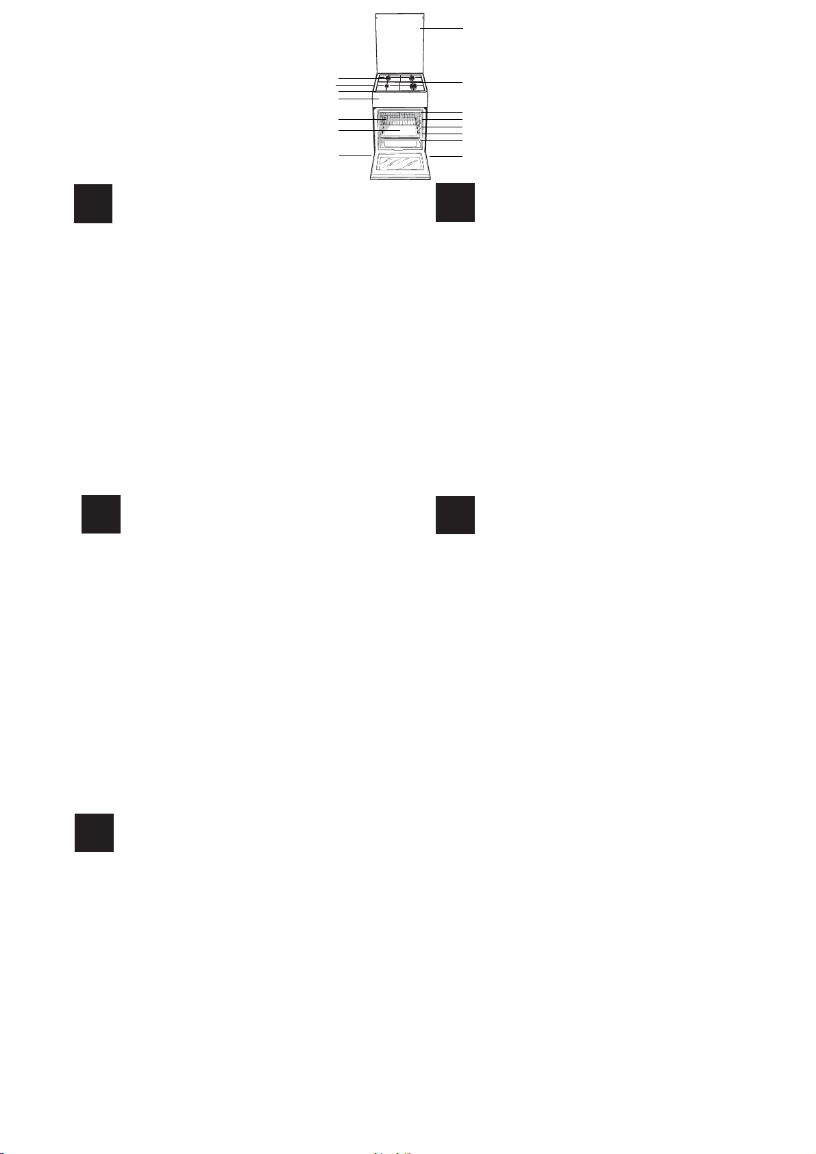
Description of the appliance
GB
Overall view
1.Hob burner
2.Hob Grid
3.Control panel
4.Sliding grill rack
5.DRIPPING pan
6..Adjustable foot
7.Containment surface for spills
8.GUIDE RAILS for the sliding racks
9.position 5
10.position 4
11.position 3
12.position 2
13.position 1
14.Glass Cover *
*Available only on certain models
1
2
3
4
5
6
LV
7
8
9
10
11
12
13
6
Ierîces apraksts
Vispariga informacija
1.Gćzes deglis
2.Plīts virsmas režģisģ
3.Vadības panelis
4.GRILĒŠANA
5.CEPE TAUKU PANNA
6. Regulējama kāja
7.Norobe˛ota virsma traipiem
8.VADOTNES slīdošo pamatņu ievietošanai un izņemšanai
9.pozīcija 5
10.pozīcija 4
11.pozīcija 3
12.pozīcija 2
13.pozīcija 1
14.Stikla pārsegs*
*Pieejams tikai noteiktiem modeļiem
PL
Opis urządzenia
Widok ogólny
1.Palnik gazowy
2. Ruszta płyty podpalnikowej
3.Panel kontrolny
4.Półka ruszt
5.Półka brytfanna
6.Nóżki regulowane
7. Płyta podpalnikowa
8.Prowadnice półek
9.pozycja 5
10.pozycja 4
11.pozycja 3
12.pozycja 2
13.pozycja 1
14.Szklana pokrywa*
*Tylko w niektórych modelach
Prietaiso aprađymas
LT
Bendras vaizdas
1. Dujų degiklis
2.Kaitlentès tinklelis
3.Valdymo pultas
4.KEPSNINÈ
5.SURINKIMO INDAS
6. Reguliuojamoji kojelè
7.TIškalų sulaikymo paviršius
8.Slankiųjų grotelių TAKELIAI
9.padètis 5
10.padètis 4
11.padètis 3
12.padètis 2
13.padètis 1
14.Stiklinis gaubtas*
*Yra tik tam tikruose modeliuose
Seadme kirjeldus
EE
Ülevaade
1.Gaasipõleti
2.Rest
3.Juhtpaneel
4.GRILL
5.TILGAPANN
6. Reguleerimisjalg
7.Tilgaalus
8.SIINID restide sisestamiseks
9.tasand 5
10.tasand 4
11.tasand 3
12.tasand 2
13. tasand 1
14.Klaaskate*
*Ainult mőnedel mudelitel
5

8
1
8
6
6
2
3
6
6
GB
Description of the appliance
Control panel
1.TIMER knob*
2.Electronic cooking programmer*
3.TIMER button*
4.COOKING TIME button*
5.COOKING END TIME button*
6.THERMOSTAT knob
7.SELECTOR knob
8.THERMOSTAT indicator light
9.Hob BURNER control knob
*Available only on certain models
7
8
8
7
9
9
7
9
2
9
3
1
7
5
4
8
9
7
6
GB
Ierîces apraksts
LV
1.TAIMERA slēdzis*
2.ELEKTRONISKAIS GATAVOŠANAS PROGRAMMĒTĀJS*
3.TAIMERA poga*
4.GATAVOŠANAS LAIKA poga*
5.GATAVOŠANAS BEIGU LAIKA poga*
6.TERMOSTATA slēdzis
7.TERMOSTATA indikatora gaisma
8.SELEKTORA slēdzis
9.DEG ĻA vadības slēdzi
*Pieejams tikai noteiktiem modeļiem
Vispariga informacija
PL
1.Pokrętło MINUTNIKA*
2.Programator elektroniczny*
3.Przycisk MINUTNIKA*
4.Przycisk CZASU PIECZENIA*
5.Przycisk KOŃCA CZASU PIECZENIA*
6.Pokrętło TERMOSTATU
7.Pokrętło PROGRAMÓW PIEKARNIKA
8.Lampka kontrolna TERMOSTATU
9.Pokr ętło PALNIKÓW PŁYTY GRZEJNEJ
Tylko w niektórych modelach
*
1.LAIKMAČIO rankenčlč *
2.Elektroninč virimo programa*
3.LAIKMAČIO mygtukas*
4.VIRIMO LAIKO mygtukas*
5.VIRIMO PABAIGOS LAIKO mygtukas*
6.TERMOSTATO rankenčlč
7.PARINKIMO rankenčlč
8.Indikacinč TERMOSTATO lemputč
9.Kaitlent čs dujř degikilř valdymo rankenčlčs
*Yra tik tam tikruose modeliuose
Panel kontrolny
LT
Prietaiso aprađymas
Valdymo pultas
Opis urządzenia
Seadme kirjeldus
EE
Juhtpaneel
1.TAIMERI nupp*
2.Elektrooniline küpsetusprogrammeerija*
3.TAIMERI nupp*
4.KÜPSETUSAJA nupp*
5.KÜPSETUSE LOPUAJA nupp
6.TERMOSTAADI nupp
7.VALIKUlüliti
8.TERMOSTAADI näidikutuli
9.POLETITE reguleernupp
*Ainult mőnedel mudelitel
6

Installation
! Before operating your new appliance please read
this instruction booklet carefully. It contains important
information concerning the safe installation and
operation of the appliance.
! Please keep these operating instructions for future
reference. Make sure that the instructions are kept with
the appliance if it is sold, given away or moved.
! The appliance must be installed by a qualified
professional according to the instructions provided.
! Any necessary adjustment or maintenance must be
performed after the cooker has been disconnected
from the electricity supply.
GB
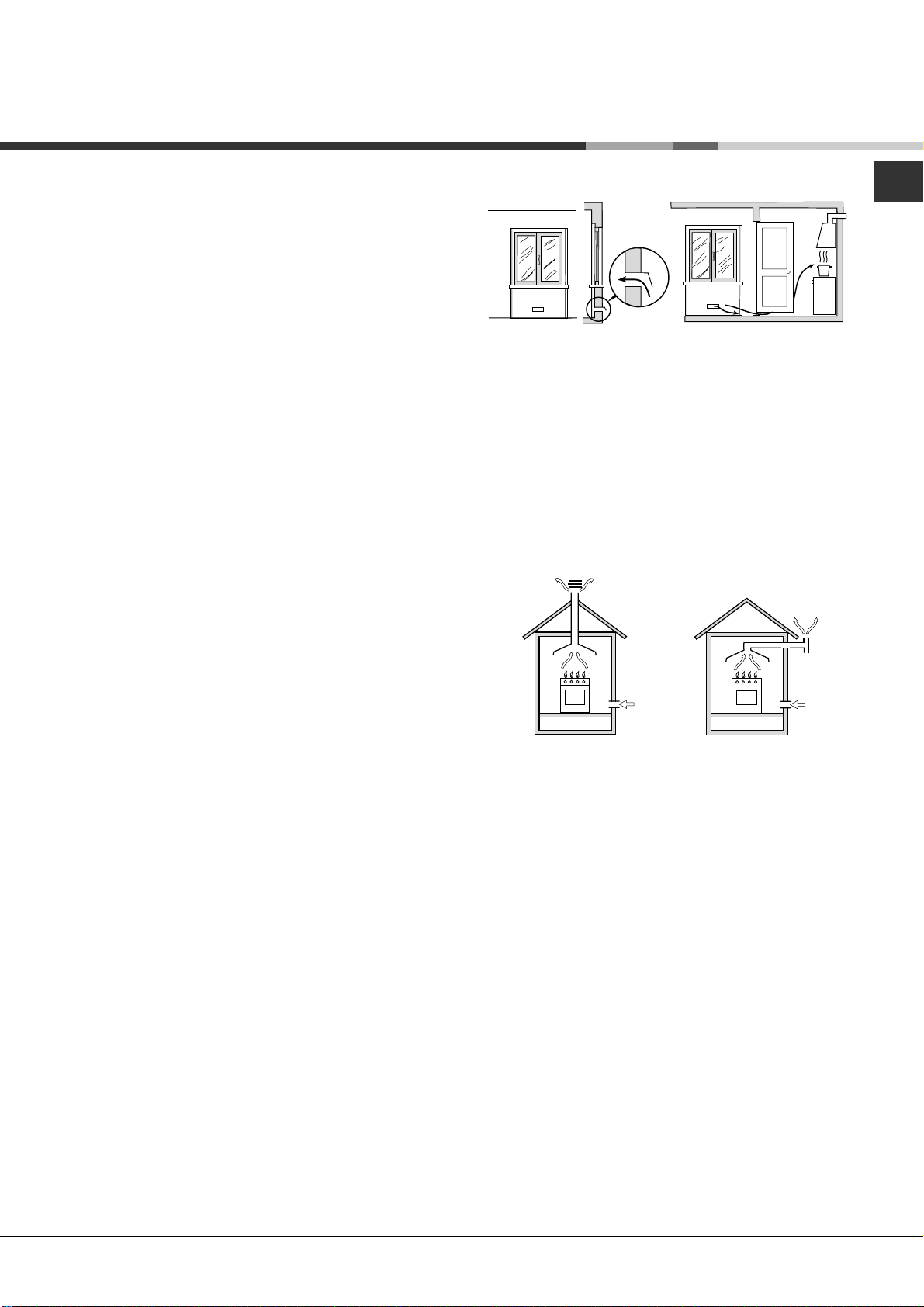
Disposing of combustion fumes
The disposal of combustion fumes should be
guaranteed using a hood connected to a safe and
efficient natural suction chimney, or using an electric
fan that begins to operate automatically every time the
appliance is switched on (see gure).
Room ventilation
The appliance may only be installed in permanentlyventilated rooms, according to current national
legislation. The room in which the appliance is installed
must be ventilated adequately so as to provide as
much air as is needed by the normal gas combustion
3
process (the flow of air must not be lower than 2 m
/h
per kW of installed power).
The air inlets, protected by grilles, should have a duct
2
with an inner cross section of at least 100 cm
and
should be positioned so that they are not liable to even
partial obstruction (see gure A).
These inlets should be enlarged by 100% - with a
2
minimum of 200 cm
- whenever the surface of the
hob is not equipped with a flame failure safety device.
When the flow of air is provided in an indirect manner
from adjacent rooms (see gure B), provided that these
are not communal parts of a building, areas with
increased fire hazards or bedrooms, the inlets should
be fitted with a ventilation duct leading outside as
described above.
Adjacent room Room requiring
A
B
ventilation
Fumes channelled
straight outside
Fumes channelled through a
chimney or a branched flue
system (reserved for cooking
appliances)
! The liquefied petroleum gases are heavier than air
and collect by the floor, therefore all rooms containing
LPG cylinders must have openings leading outside so
that any leaked gas can escape easily.
LPG cylinders, therefore, whether partially or
completely full, must not be installed or stored in rooms
or storage areas that are below ground level (cellars,
etc.). Only the cylinder being used should be stored
in the room; this should also be kept well away from
sources of heat (ovens, chimneys, stoves) that may
cause the temperature of the cylinder to rise above
50°C.
Positioning and levelling
! It is possible to install the appliance alongside
cupboards whose height does not exceed that of the
hob surface.
! Make sure that the wall in contact with the back of
the appliance is made from a non-flammable, heatresistant material (T 90°C).
A
Ventilation opening for
comburent air
Increase in the gap
between the door and
the flooring
! After prolonged use of the appliance, it is advisable to
open a window or increase the speed of any fans used.
To install the appliance correctly:
• Place it in the kitchen, dining room or the bed-sit (not
in the bathroom).
• If the top of the hob is higher than the cupboards,
the appliance must be installed at least 200 mm away
from them.
• If the cooker is installed underneath a wall cabinet,
there must be a minimum distance of 420 mm
between this cabinet and the top of the hob.
7

GB
HOOD
420
Min.
min.
650
mm. with hood
min.
700
mm. without hood
mm.
600
Min. mm.
420
Min. mm.
• If the cooker is
installed underneath a
wall cabinet, there must
be a minimum distance
of 420 mm between this
cabinet and the top of
the hob.
This distance should be
increased to 700 mm
if the wall cabinets are
flammable (see gure).
• Do not position blinds behind the cooker or less than
200 mm away from its sides.
• Any hoods must be installed according to the
instructions listed in the relevant operating manual.
• The voltage is in the range between the values
indicated on the data plate.
• The socket is compatible with the plug of the
appliance. If the socket is incompatible with the
plug, ask an authorised technician to replace it. Do
not use extension cords or multiple sockets.
! Once the appliance has been installed, the power
supply cable and the electrical socket must be easily
accessible.
! The cable must not be bent or compressed.
! The cable must be checked regularly and replaced
by authorised technicians only.
Levelling
If it is necessary to level the
appliance, screw the adjustable
feet into the places provided on
each corner of the base of the
cooker (see gure).
The legs* fit into the slots on the
underside of the base of the
cooker.
Electrical connection
Install a standardised plug corresponding to the load
indicated on the appliance data plate (see Technical
data table).
The appliance must be directly connected to the
mains using an omnipolar circuit-breaker with a
minimum contact opening of 3 mm installed between
the appliance and the mains. The circuit-breaker must
be suitable for the charge indicated and must comply
with NFC 15-100 regulations (the earthing wire must
not be interrupted by the circuit-breaker). The supply
cable must be positioned so that it does not come into
contact with temperatures higher than 50°C at any
point.
Before connecting the appliance to the power supply,
make sure that:
• The appliance is earthed and the plug is compliant with
the law.
• The socket can withstand the maximum power of the
appliance, which is indicated by the data plate.
8
! The manufacturer declines any liability should
these safety measures not be observed.
Gas connection
Connection to the gas network or to the gas cylinder
may be carried out using a flexible rubber or steel hose,
in accordance with current national legislation and after
making sure that the appliance is suited to the type of
gas with which it will be supplied (see the rating sticker
on the cover: if this is not the case see below). When
using liquid gas from a cylinder, install a pressure
regulator which complies with current national
regulations. To make connection easier, the gas
supply may be turned sideways*: reverse the position
of the hose holder with that of the cap and replace the
gasket that is supplied with the appliance.
! Check that the pressure of the gas supply is
consistent with the values indicated in the Table
of burner and nozzle specifications (see below).
This will ensure the safe operation and durability of
your appliance while maintaining efficient energy
consumption.
Gas connection using a flexible rubber hose
Make sure that the hose complies with current national
legislation. The internal diameter of the hose must
measure: 8 mm for liquid gas supply; 13 mm for
methane gas supply.
Once the connection has been performed, make sure
that the hose:
• Does not come into contact with any parts that
reach temperatures of over 50°C.
• Is not subject to any pulling or twisting forces and
that it is not kinked or bent.
• Does not come into contact with blades, sharp
corners or moving parts and that it is not
compressed.
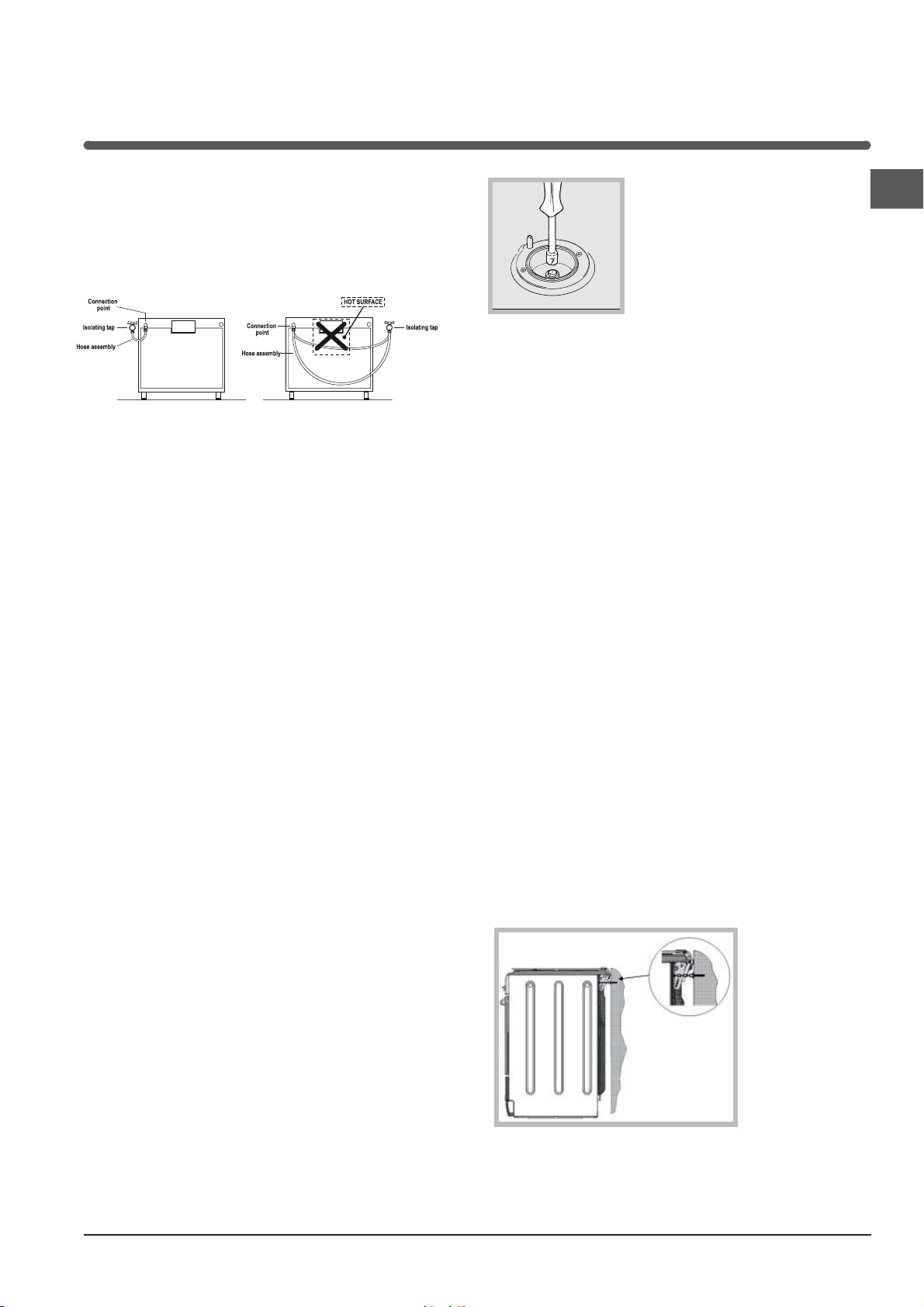
• Is easy to inspect along its whole length so that its
condition may be checked.
• Is shorter than 1500 mm.
• Fits firmly into place at both ends, where it will
be fixed using clamps that comply with current
regulations.
! If one or more of these conditions is not fulfilled
or if the cooker must be installed according to the
conditions listed for class 2 - subclass 1 appliances
(installed between two cupboards), the flexible steel
hose must be used instead (see below).
Connecting a flexible jointless stainless steel pipe
to a threaded attachment
Make sure that the hose and gaskets comply with
current national legislation.
To begin using the hose, remove the hose holder on
the appliance (the gas supply inlet on the appliance is
a cylindrical threaded 1/2 gas male attachment).
! Perform the connection in such a way that the hose
length does not exceed a maximum of 2 metres,
making sure that the hose is not compressed and does
not come into contact with moving parts.
Checking the tightness of the connection
When the installation process is complete, check the
hose fittings for leaks using a soapy solution. Never
use a flame.
2. Unscrew the nozzles using
GB
a 7 mm socket spanner (see
gure), and replace them with
nozzles suited to the new type
of gas (see Burner and nozzle
speci cations table).
3. Replace all the components
by following the above
instructions in reverse.
Adjusting the hob burners’ minimum setting:
1. Turn the tap to the minimum position.
2. Remove the knob and adjust the regulatory screw,
which is positioned inside or next to the tap pin, until
the flame is small but steady.
! If the appliance is connected to a liquid gas supply,
the regulatory screw must be fastened as tightly as
possible.
3. While the burner is alight, quickly change the
position of the knob from minimum to maximum and
vice versa several times, checking that the flame is not
extinguished.
! The hob burners do not require primary air
adjustment.
! After adjusting the appliance so it may be used with
a different type of gas, replace the old rating label with
a new one that corresponds to the new type of gas
(these labels are available from Authorised Technical
Assistance Centres).
! Should the gas pressure used be different (or vary
slightly) from the recommended pressure, a suitable
pressure regulator must be fitted to the inlet hose in
accordance with current national regulations relating to
“regulators for channelled gas”.
Adapting to different types of gas
It is possible to adapt the appliance to a type of gas
other than the default type (this is indicated on the
rating label on the cover).
Adapting the hob
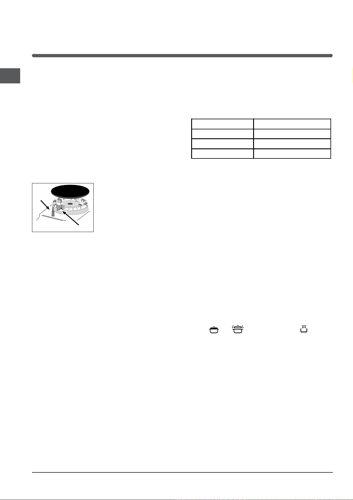
Replacing the nozzles for the hob burners:
1. Remove the hob grids and slide the burners off their
seats.
Safety Chain
! In order
to prevent
accidental
tipping of the
appliance, for
example by
a child climbing onto the
oven door, the
supplied safety
chain MUST be
installed!
The cooker is fitted with a safety chain to be fixed by
means of a screw (not supplied with the cooker) to
the wall behind the appliance, at the same height as
the chain is attached to the appliance.
9
GB
Choose the screw and the screw anchor according
to the type of material of the wall behind the appliance. If the head of the screw has a diameter smaller
than 9mm, a washer should be used. Concrete wall
requires the screw of at least 8mm of diameter, and
60mm of length.
Ensure that the chain is fixed to the rear wall of the
cooker and to the wall, as shown in figure, so that
after installation it is tensioned and parallel to the
ground level.
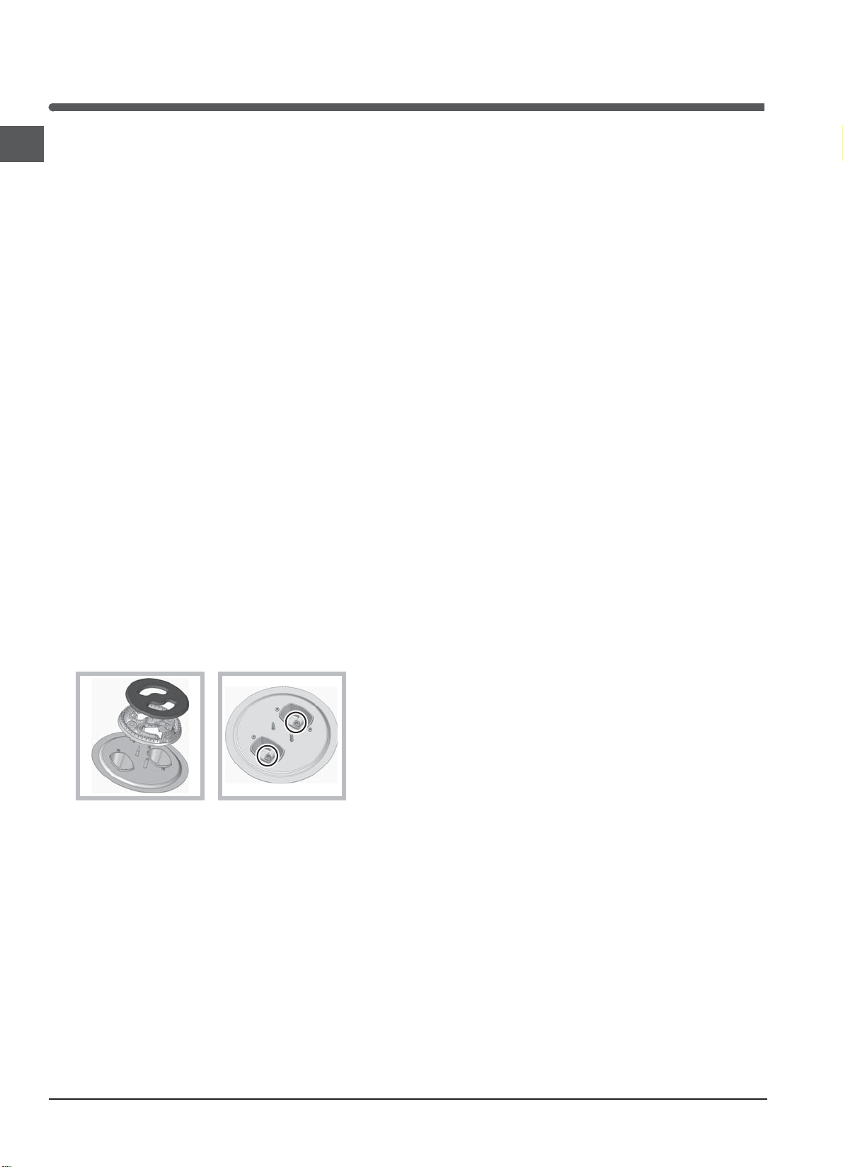
Replacing the Triple ring burner nozzles
1. Remove the pan supports and lift the burners out
of their housing. The burner consists of two
separate parts (see pictures).
2. Unscrew the nozzles using a 7 mm socket
spanner. Replace the nozzles with models that are
configured for use with the new type of gas (see
Table 1). The two nozzles have the same hole
diameter.
3. Replace all the components by completing the
above operations in reverse order.
*
the position of the knob from minimum to
maximum and vice versa several times, checking
that the flame does not go out.
(thermocouple) fitted. If the device fails to work
when the burners are set to the low flame setting,
increase this low flame setting using the adjusting
screw.
seals on the by-passes using sealing wax
5. Once the adjustment has been made, replace the
! If the appliance is connected to liquid gas, the
regulation screw must be fastened as tightly as
possible.
! Once this procedure is finished, replace the old
rating sticker with one indicating the new type of gas
used. Stickers are available from any of our Service
Centres.
! Should the gas pressure used be different (or vary
slightly) from the recommended pressure, a suitable
pressure regulator must be fitted to the inlet pipe (in
order to comply with current national regulations).
• Adjusting the burners’ primary air :
Does not require adjusting.
• Setting the burners to minimum:
1. Turn the tap to the low flame position.
2. Remove the knob and adjust the adjustment
screw, which is positioned in or next to the tap pin,
until the flame is small but steady.
setting, while the burner is alight, quickly change
Only available in certain models.
*
10
S
S
R
A
S
S
A
I5GMH6AG.1 U
I5GMH6AG U
I5GMH2AG U
I5GMH5AG U
I5GMHA U
I5GMH1A U
I5GMH5AG U
I5GMH6AG U
TC
I5TMH6AG U
I5TMH5AG.1 U
TABLE OF CHARACTERISTSICS
Dimensions
Volume
Dimensions of the
lower compartment
Burners
Voltage and
frequency
ENERGY LABEL
width
height
depth
I5GMH2AG U
I5GMH5AG U
I5GMHA U
I5GMH1A U
I5GMH5AG U
I5GMH6AG U
width 42 cm
height 23 cm
depth 44 cm
may be adapted for use with any type
of gas shown on the data plate, which
is located inside the flap or, after the
oven compartment has been opened,
on the left-hand wall inside the oven.
see data plate
Directive 2002/40/EC on the label of
electric ovens.
Standard EN 50304
Energy consumption for Natural
convection – heating mode:
Convection;
Declared energy consumption for
Forced convection Class – heating
mode: Baking
391
340
424
mm
mm
mm
(with drawn guide rails)
width
height
depth
I5TMH6AG U
I5GMH6AG.1 U
57l
I5GMH6AG U
I5TMH5AG.1 U
410
340
424
mm
mm
mm
GB
60l
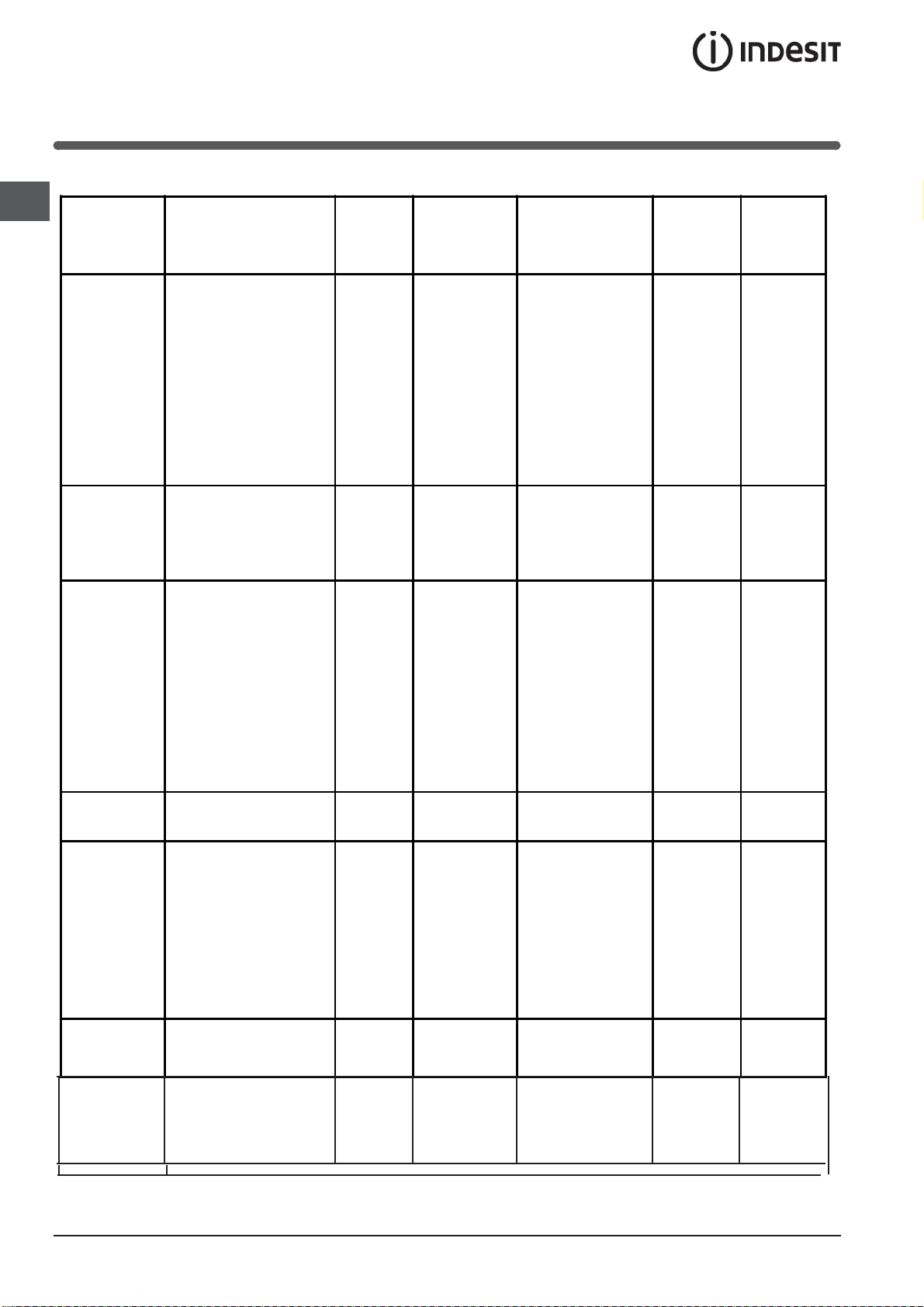
Table of burner and nozzle specifications
This appliance conforms to the
Data plate, is located inside the flap or, after the oven
following European Economic
Community directives: 2006/95/EC
dated 12/12/06 (Low Voltage) and
subsequent amendments 2004/108/EC dated 15/12/04
(Electromagnetic Compatibility) and
subsequent amendments - 93/68/EEC
dated 22/07/93 and subsequent
amendments.
2002/96/EC
2009/142 of 30/11/09 (Gas)
1275/2008 (Stand-by/ Off mode)
compartment has been opened, on the left-hand wall
inside the oven.
Table 1 G30 (GPB-B) G20 (GZ50) G2.350 (GZ35)
Burner Diameter
Fast (Large)(R) 100 0,70 3,40 41 87 247 3,00 128 286 3,00 158 397
Semi Fast
(Medium) (S)
Auxiliary (Small)
(A)
(mm)
Tripple
Crown (TC)
Supply
Pressures
Minimum (mbar)
Nominal (mbar)
Maximum (mbar)
Thermal
power
(p.c.s.*)
Reduc. Nominal (mm) (mm) Nominal (mm) Nominal (mm)
75 0,40 2,20 30 70 160 1,90 104 181 1,9 143 X 251
51 0,40 1,30 30 52 95 1,00 76 95 1,00 106 132
130 3.25 1.5 63
kW
Thermal
power
kW
(p.c.s.*)
By-pass
1/100
29
37
44
Nozzle
1/100
2x65
Flow*
Thermal
g/h
power
kW
(p.c.s.*)
262 3,25
Nozzle
1/100
2x99 309
Flow*
l/h
16
20
25
Thermal
* A 15°C e 1013 mbar-dry gas
G2.350 (GZ35) p.c.s. 27.20 MJ/m
power
G20 (GZ50) p.c.s. 37,78 MJ/m
G30 (GPB-B) p.c.s. 49,47 MJ/Kg
(p.c.s.*)
Nozzle
1/100
kW
10
13
16
( )
Flow*
l/h
11
Start-up and use
X
C
GB
Using the hob
Lighting the burners
For each BURNER knob there is a full ring showing the
strength of the flame for the relevant burner.
To light one of the burners on the hob:
1. Bring a flame or gas lighter close to the burner.
2. Press the BURNER knob and turn it in an
anticlockwise direction so that it is pointing to the
maximum flame setting .
3. Adjust the intensity of the flame to the desired level
by turning the BURNER knob in an anticlockwise
direction. This may be the minimum setting , the
maximum setting or any position in between the two.
If the appliance is fitted with an electronic lighting
device* (C), press the
BURNER knob and turn it in
an anticlockwise direction,
towards the minimum flame
setting, until the burner
is lit. The burner may be
extinguished when the knob
is released. If this occurs,
repeat the operation, holding the knob down for a longer
period of time.
f the appliance is equipped with a flame failure safety
device (X), press and hold the BURNER knob for
approximately 3-7 seconds to keep the flame alight
and to activate the device.
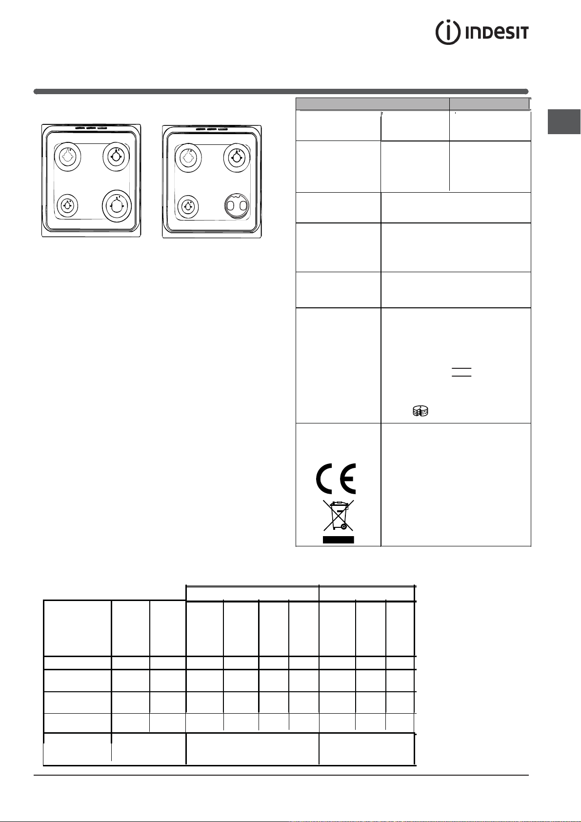
Practical advice on using the burners
For the burners to work in the most efficient way
possible and to save on the amount of gas consumed,
it is recommended that only pans that have a lid and
a flat base are used. They should also be suited to the
size of the burner:
Burner ř Cookware diameter (cm)
Fast (R) 24 - 26
Semi Fast (S) 16 - 20
Auxiliary (A) 10 - 14
To identify the type of burner, please refer to the
diagrams contained in the “Burner and nozzle
specifications”.
(TC)
Using the oven
! The first time you use your appliance, heat the empty
oven with its door closed at its maximum temperature
for at least half an hour. Ensure that the room is well
ventilated before switching the oven off and opening
the oven door. The appliance may emit a slightly
unpleasant odour caused by protective substances
used during the manufacturing process burning away.
! Before operating the product, remove all plastic film
from the sides of the appliance.
! If the flame is accidentally extinguished, switch off the
burner and wait for at least 1 minute before attempting
to relight it.
To switch the burner off, turn the knob until it reaches
the stop position •.
Only available in certain models.
*
! Never put objects directly on the bottom of the oven;
this will avoid the enamel coating being damaged.
! Should the appliance be equipped with an electronic
programmer*, to use the electric oven, just press
buttons
will appear on the display) before selecting the desired
cooking function.
1. Select the desired cooking mode by turning the
SELECTOR knob.
2. Select the recommended temperature for the
cooking mode or the desired temperature by turning
the THERMOSTAT knob.
A list detailing cooking modes and suggested cooking
temperatures can be found in the relevant table (see
Oven cooking advice table).
During cooking it is always possible to:
• Change the cooking mode by turning the
SELECTOR knob.
• Change the temperature by turning the
THERMOSTAT knob.
and at the same time (the symbol
12
• Stop cooking by turning the SELECTOR knob to the
“0” position.
! Always place cookware on the rack(s) provided.
THERMOSTAT indicator light
When this is illuminated, the oven is generating heat.
It switches off when the inside of the oven reaches
the selected temperature. At this point the light
illuminates and switches off alternately, indicating
that the thermostat is working and is maintaining the
temperature at a constant level.
Oven light
This is switched on by turning the SELECTOR knob to
any position other than “0”. It remains lit as long as the
with the knob, the
oven is operating. By selecting
light is switched on without any of the heating elements
being activated.
Timer*
To activate the Timer proceed as follows:
1. Turn the TIMER knob in a clockwise direction for
almost one complete revolution to set the buzzer.
2. Turn the TIMER knob in an anticlockwise direction
to set the desired length of time.
Cooking modes
BAKING mode
Temperature: any temperature between 50°C and Max.
The rear heating element and the fan come on,
guaranteeing delicate heat distributed uniformly
throughout the oven.
This mode is ideal for baking and cooking delicate
foods - especially cakes that need to rise - and for the
preparation of certain tartlets on 3 shelves at the same
time. Here are a few examples: cream puffs, sweet and
savoury biscuits, savoury puffs, Swiss rolls and small
portions of vegetables au gratin, etc…..
CONVECTION mode
Temperature: any temperature between 50°C and Max.
On this setting, the top and bottom heating elements
come on. This is the classic, traditional type of oven
which has been perfected, with exceptional heat
distribution and reduced energy consumption. The
convection oven is still unequalled when it comes to
cooking dishes made up of several ingredients, e.g.
cabbage with ribs, Spanish style cod, Ancona style
stockfish, tender veal strips with rice, etc. Excellent
results are achieved when preparing veal or beefbased dishes as well (braised meats, stew, goulash,
wild game, ham etc.) which need to cook slowly and
require basting or the addition of liquid. It nonetheless
remains the best system for baking cakes as well as
fruit and cooking using covered casserole dishes
for oven baking. When cooking in convection mode,
only use one dripping pan or cooking rack at a time,
otherwise the heat distribution will be uneven. Using
the different rack heights available, you can balance
the amount of heat between the top and the bottom of
the oven. Select from among the various rack heights
based on whether the dish needs more or less heat
from the top.
FAN ASSISTED mode
Temperature: any temperature between 50°C and Max.
The heating elements, as well as the fan, will come
on. Since the heat remains constant and uniform
throughout the oven, the air cooks and browns food
uniformly over its entire surface. With this mode, you
can also cook various dishes at the same time, as
long as their respective cooking temperatures are the
same. A maximum of 2 racks can be used at the same
time, following the instructions in the section entitled:
“Cooking On More Than One Rack”.
This fan assisted mode is particularly recommended
for dishes requiring a gratin finish or for those
requiring considerably prolonged cooking times,
such as for example: lasagne, pasta bakes, roast
chicken and potatoes, etc… Moreover, the excellent
heat distribution makes it possible to use lower
temperatures when cooking roasts. This results in
less loss of juices, meat which is more tender and a
decrease in the loss of weight for the roast. The fan
assisted mode is especially suited for cooking fish,
which can be prepared with the addition of a limited
amount of condiments, thus maintaining their flavour
and appearance.
Desserts: the fan assisted mode is also perfect for
baking leavened cakes.
Moreover, this mode can also be used to thaw quickly
white or red meat and bread by setting the temperature
to 80 °C. To thaw more delicate foods, set the
thermostat to 60°C or use only the cold air circulation
feature by setting the thermostat to 0°C.
OPOP
TT
VEN VEN
OO
VEN
O
VEN VEN
OO
The central part of the top heating element is switched
on. The high and direct temperature of the grill is
recommended for food that requires a high surface
temperature (veal and beef steaks, fillet steak and
entrecôte). This cooking mode uses a limited amount
of energy and is ideal for grilling small dishes. Place
the food in the centre of the rack, as it will not be cooked
properly if it is placed in the corners.
modemode
mode
PIZZA
The circular heating elements and the elements at the
bottom of the oven are switched on and the fan is
activated. This combination heats the oven rapidly by
Only available in certain models.
*
modemode
T
TT
OP
OPOP
mode
GB
13
GB
producing a considerable amount of heat, particularly
from the element at the bottom. If you use more than
one rack at a time, switch the position of the dishes
halfway through the cooking process.
*
*
DOUBLE GRILL mode
BOTTOM VENTILATED mode
The bottom heating element and the fan is activated,
which allows for the heat distribution within the whole
cavity of the oven. This combination is useful for light
cooking of vegetables and fish.
The top heating element and the rotisserie spit will be
activated.
This provides a larger grill than the normal grill setting
and has an innovative design that improves cooking
efficiency by 50% and eliminates the cooler corner
areas. Use this grilling mode to achieve a uniform
browning on top of the food.
**
F FAN
The top heating element and the turnspit are activated
and the fan begins to operate. This combination of
features increases the effectiveness of the unidirectional
thermal radiation of the heating elements through forced
circulation of the air throughout the oven. This prevents
the food from burning on top by enabling heat to penetrate
into the food more effectively; it is therefore an ideal
way of cooking food quickly under the grill or for grilling
large pieces of meat without having to use the turnspit.
! The GRILL, DOUBLE GRILL and FAN-ASSISTED
DOUBLE GRILL cooking modes must be performed with
the oven door shut.
! When using the GRILL and DOUBLE GRILL cooking
modes, place the rack in position 5 and the dripping
pan in position 1 to collect cooking residues (fat and/or
grease). When using the FAN-ASSISTED DOUBLE
GRILL cooking mode, place the rack in position 2 or 3
and the dripping pan in position 1 to collect cooking
residues.
DEFROSTING mode
The fan located on the bottom of the oven makes the
air
circulate at room temperature around the food. This is
recommended for the defrosting of all types of food, but
in
particular for delicate types of food which do not require
heat, such as for example: ice cream cakes, cream or
custard desserts, fruit cakes. By using the fan, the
defrosting time is approximately halved. In the case
of
meat, fish and bread, it is possible to accelerate the
process using the “multi-cooking” mode and setting
the temperature to 80° - 100°C.
ASSISTED DOUBLE GRILL mode
BOTTOM mode BOTTOM mode
The lower heating element is activated. This position
is recommended for perfecting the cooking of dishes
(in baking trays) which are already cooked on the
surface but require further cooking in the centre, or
for desserts with a covering of fruit or jam, which only
require moderate colouring on the surface. It should
be noted that this function does not allow the
maximum
temperature to be reached inside the oven (250°C)
and it is therefore not recommended that foods are
cooked using only this setting, unless you are baking
cakes (which should be baked at a temperature of
180°C or lower).
Practical cooking advice
Cooking on several shelves simultaneously
If it is necessary to use two racks, use the FAN
ASSITED mode , as this is the only cooking mode
suited to this type of cooking. We also recommend
that:
• Positions 1 and 5 are not used. This is because
excessive direct heat can burn temperature
sensitive foods.
• Positions 2 and 4 are used and that food that
requires more heat is placed on the rack in position
2.
• When cooking foods that require different cooking
times and temperatures, set a temperature
that is halfway between the two recommended
temperatures (see Oven cooking advice table) and
place the more delicate food on the rack in position
4. Remove the food that requires a shorter cooking
time first.
• When cooking pizzas on several racks with the
temperature set to 220°C, the oven is preheated for
15 minutes. Generally speaking, cooking on the rack
in position 4 takes longer: we recommend that the
pizza cooked on the lowest rack position is removed
first, followed by the pizza cooked in position 4 a few
minutes later.
• Place the dripping pan on the bottom and the rack
on top.
Only available in certain models.
*
14
GB
Rotisserie
3. Activate the rotisserie by selecting
SELECTOR knob.
Lower oven compartment*
There is a compartment underneath the oven that may
be used to storeoven accessories or deep dishes. To
open the door pull it downwards (see gure).
*
To operate the
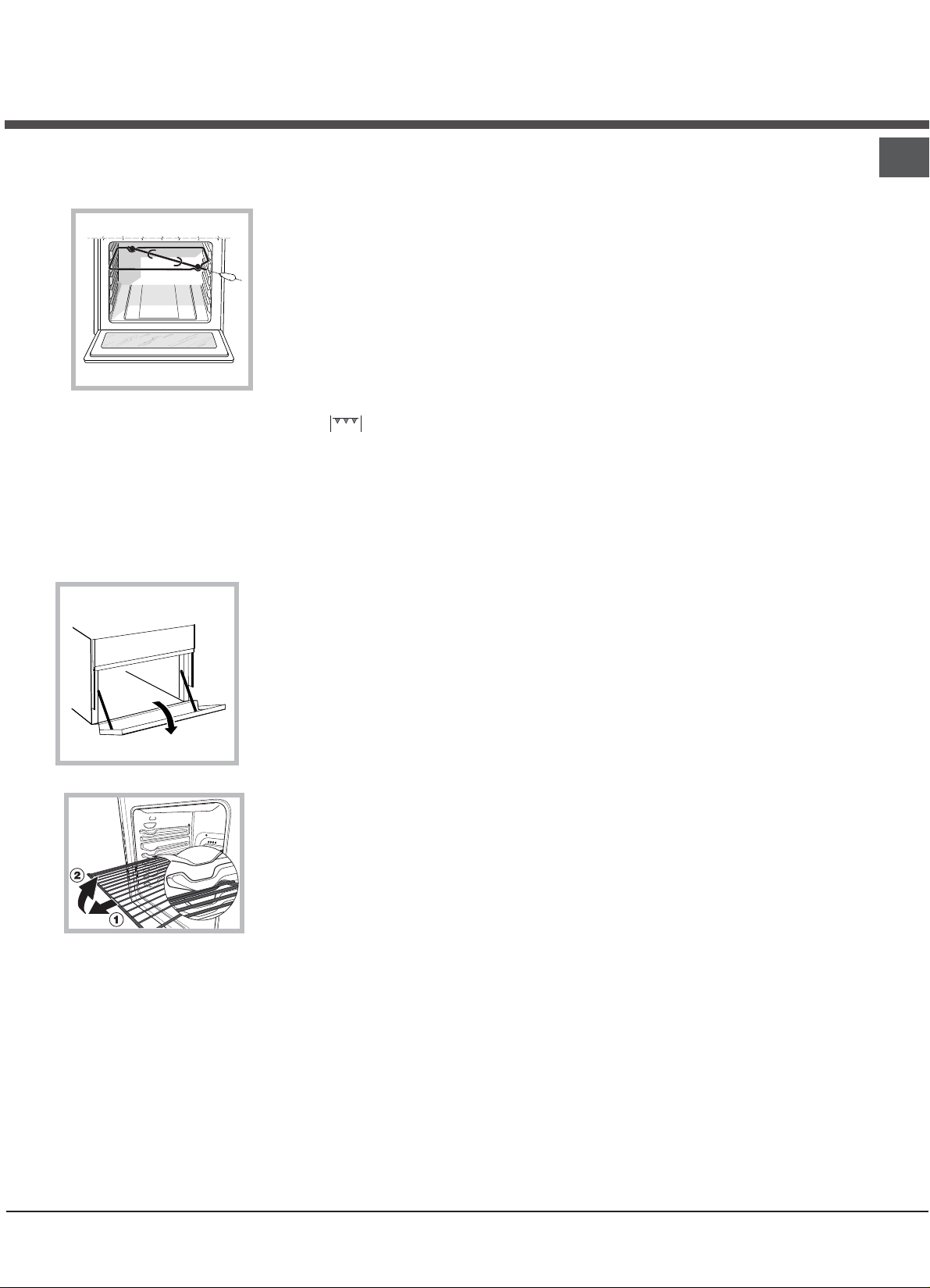
rotisserie (see diagram)
proceed as follows:
1. Place the dripping
pan in position 1.
2. Place the rotisserie
support in position 4
and insert the spit in
the hole provided on
the back panel of the
oven.
with the
! Do not place
flammable materials
in the lower oven
compartment.
! The internal surfaces of
the compartment (where
present) may become
hot.
WARNING! The oven is
provided with a stop system to extract the racks
and prevent them from
coming out of the oven.(1)
As shown in the drawing,
to extract them completely, simply lift the racks,
holding them on the front
part, and pull (2).
Only available in certain models.
*
15
GB
Electronic timer*
This function displays the time and works as a timer
which counts down to zero.
! All functions will be implemented approximately 7
seconds after they have been set.
Resetting the clock
After the appliance has been connected to the power
supply, or after a power cut, the clock display will
begin to blink, showing the figure: 0:00
• Press button
exact time. Press and hold the buttons to quicken
the count upwards.
Any necessary modifications can be made by
repeating the above process.
Timer feature
This function may be accessed by pressing the
button, after which the display will show the symbol
. Every time the + button is pressed it corresponds
to a time increase of 10 seconds, until it reaches 99
minutes and 50 seconds. After this point, each press of
the button represents an increase of one minute, up to a
maximum of 10 hours.
Pressing the - button reduces the time.
After the time period has been set, the timer will begin
to count down. When the timer reaches zero, the
buzzer will sound (this may be stopped by pressing
any button).
The time may be displayed by pressing the
and the symbol indicates that the timer function has
been set. After approximately 7 seconds, the display will
automatically revert to the timer.
Cancelling a time that has already been set
Press the - button until the display shows 0:00.
Adjusting the buzzer volume
After selecting and confirming the clock settings, use
the - button to adjust the volume of the alarm buzzer.
and then buttons - and + to set the
button,
Planning cooking with the electronic
programmer*
Setting the clock
After the appliance has been connected to the
power supply, or after a blackout, the display will
automatically reset to 0:00 and begin to blink. To set
the time:
1. Press the COOKING TIME button
COOKING END TIME simultaneously.
2. Within 4 seconds of having pressed these buttons,
set the exact time by pressing the + and - buttons.
The + button advances the hours and the
decreases the hours.
Once the time has been set, the programmer
automatically switches to manual mode.
Setting the timer
The timer enables a countdown to be set, when the
time has elapsed a buzzer sounds.
To set the timer proceed as follows:
1. press the TIMER button
. The display shows:
and the
- button
.
2. Press the + and - buttons to set the desired time.
3. When the buttons are released the timer begins
counting down and the current time appears on the
display.
4. After the time has elapsed a buzzer will sound, and
this can be switched off by pressing any button (except
the + and - buttons). The symbol
! The timer does not switch the oven on or off.
Adjusting the volume of the buzzer
After selecting and confirming the clock settings, use
the - button to adjust the volume of the alarm buzzer.
Setting the cooking time with a delayed start
First decide which cooking mode you wish to use and
set a suitable temperature using the SELECTOR and
THERMOSTAT knobs on the oven.
At this point it is possible to set the cooking time:
1. Press the COOKING TIME button
2. Within 4 seconds of having pressed this button, set
the desired amount of time by pressing the + and buttons. If, for example, you wish to set a cooking time
of 30 minutes, the display will show:
will switch off.
.
Only available in certain models.
*
16
3. 4 seconds after the buttons are released, the current
time (for example 10.00) reappears on the display with
and the letter A (AUTO).
the symbol
Next the desired cooking end time must be set:
4. Press the END COOKING TIME button
5. Within 4 seconds of having pressed this button,
adjust the cooking end time by pressing the + and buttons. If, for example, you want cooking to end at
13.00, the display shows:
.
6. 4 seconds after the buttons are released, the current
time (for example 10.00) reappears on the display with
the letter A (AUTO).
At this point, the oven is programmed to switch on
automatically at 12:30 and switch off after 30 minutes,
at 13.00.
Setting the cooking time with an immediate start
Follow the above procedure for setting the cooking
time (points 1-3).
versa.
If the oven has already been programmed, it will not
accept cooking end times which are before the start of
the programmed cooking process.
End-cooking Timer *
1. To set the buzzer, turn the COOKING TIMER knob
clockwise almost one complete revolution.
2. Turn the knob anticlockwise to set the desired time:
align the minutes shown on the COOKING TIMER knob
with the indicator on the control panel.
3. When the selected time has elapsed, a buzzer
sounds and the oven turns off.
4. When the oven is off the cooking timer can be used
as a normal timer.
! To use the oven manually, in other words when you
do not wish to use the end of cooking timer, turn the
COOKING TIMER knob until it reaches the symbol.
GB
! When the letter A appears, this indicates that both
the cooking time and the end cooking time have been
programmed in AUTO mode. To restore the oven to
manual operation, after each AUTO cooking mode
press the COOKING TIME
TIME buttons simultaneously.
! The symbol
the entire duration of the cooking programme.
The set cooking duration can be displayed at any time
by pressing the COOKING TIME button
cooking end time may be displayed by pressing the
END COOKING TIME button . When the cooking
time has elapsed a buzzer sounds. To stop it, press
any button apart from the + and - buttons.
Cancelling a previously set cooking programme
Press the COOKING TIME button
COOKING END TIME simultaneously.
Correcting or cancelling previously set data
The data entered can be changed at any time by
pressing the corresponding button (TIMER, COOKING
TIME or COOKING END TIME) and the + or - button.
When the cooking time data is cancelled, the cooking
end time data is also cancelled automatically, and vice
will remain lit, along with the oven, for
and END COOKING
, and the
and the
Only available in certain models.
*
17
GB
Oven cooking advice table
Selector knob
setting
Food to be cooked Weight
(in kg)
Cooking rack
position from
bottom
Preheating time
(minutes)
Thermostat
knob
setting
Cooking
time
(minutes)
Baking
Convection
Fan assisted
Top Oven
Tarts
Fruit cakes
Plum cake
Sponge cake
Stuffed pancakes (on 2
racks)
Small cakes (on 2 racks)
Cheese puffs (on 2
racks)
Cream puffs (on 3 racks)
Biscuits (on 3 racks)
Meringues (on 3 racks)
Duck
Roast veal or beef
Pork roast
Biscuits (short pastry)
Tarts
Pizza (on 2 racks)
Lasagne
Lamb
Roast chicken +
potatoes Mackerel
Plum-cake
Cream puffs (on 2 racks)
Biscuits (on 2 racks)
Sponge cake (on 1 rack)
Sponge cake (on 2
racks)
Savoury pies
Browning food to perfect
cooking
0.5
0.7
0.5
1.2
0.6
0.4
0.7
0.7
0.5
0.5
0.5
0.5
1.0
1.5
3
1
2/3
3
3
2-4
2-4
2-4
1-3-5
1-3-5
1-3-5
1
1
1
1
1
1
1
1
1
1
3
3
3
3
3
2-4
3
2
2-4
2
2
2-4
2-4
2
2-4
3
15
15
15
15
15
15
15
15
15
15
15
15
15
15
15
15
10
10
10
10
10
10
10
10
10
15
180
180
180
160
200
190
210
180
180
90
200
200
200
180
180
220
200
180
180
180
170
190
180
170
170
200
- 3/4 15 220 -
20-30
40-45
40-50
25-30
30-35
20-25
15-20
20-25
20-25
180
65-75
70-75
70-80
15-20
30-35
15-20
30-35
50-60
60-75
30-35
40-50
20-25
10-15
15-20
20-25
25-30
Grill
Soles and cuttlefish
1
4
5
Max
Squid and prawn
kebabs
Cod filet
Grilled vegetables
Veal steak
Cutlets
Hamburgers
Mackerels
Toasted sandwiches
Fan assisted
grill
Bottom
Ventilated
Bottom Mode
!
cooking times are approximate and may vary according to personal taste. When cooking using the grill or fan
Grilled chicken
Cuttlefish
Bream
Cod sh llet
Sea bass in foil
Mixed vegetables
(Ratatouille type)
Well-done vegetables
For perfectioning cooking
1
1
1
1
1
1
1
n.° 4
1.5
1.5
0.5
0.5
0.5
0.8 – 1,0
1,5 – 2,0
4
4
3/4
4
4
4
4
4
3
3
3
3
3
3
3
5
5
5
5
5
5
5
5
5
5
18
16
24
21
20
Max
Max
Max
Max
Max
Max
Max
Max
200
200
170-180
160-170
200-210
190 -200
180 - 190
assisted grill, the dripping pan must always be placed on the 1st oven rack from the bottom.
17
8-10
6-8
10
10-15
15-20
15-20
7-10
15-20
2-3
55-60
30-35
25-35
15-20
35-45
50 - 60
55 - 60
Precautions and tips
! This appliance has been designed and manufactured
in compliance with international safety standards.
The following warnings are provided for safety reasons
and must be read carefully.
General safety
• The appliance was designed for domestic use inside
the home and is not intended for commercial or
industrial use.
• The appliance must not be installed outdoors, even in
covered areas. It is extremely dangerous to leave the
appliance exposed to rain and storms.
• Do not touch the appliance with bare feet or with wet
or damp hands and feet.
• The appliance must be used by adults only for
the preparation of food, in accordance with the
instructions provided in this booklet.
• The instruction booklet accompanies a class 1
(insulated) or class 2 - subclass 1 (recessed
between 2 cupboards) appliance.
• Keep children away from the oven.
• Make sure that the power supply cables of other
electrical appliances do not come into contact with
the hot parts of the oven.
• The openings used for the ventilation and dispersion
of heat must never be covered.
• Always use oven gloves when placing cookware in
the oven or when removing it.
• Do not use flammable liquids (alcohol, petrol, etc...)
near the appliance while it is in use.
• Do not place flammable material in the lower storage
compartment or in the oven itself. If the appliance is
switched on accidentally, it could catch fire.
” position
• Always make sure the knobs are in the “
when the appliance is not in use.
• When unplugging the appliance, always pull the plug
from the mains socket; do not pull on the cable.
• Never perform any cleaning or maintenance work
without having disconnected the appliance from the
electricity mains.
• If the appliance breaks down, under no
circumstances should you attempt to repair
the appliance yourself. Repairs carried out by
inexperienced persons may cause injury or further
malfunctioning of the appliance. Contact Assistance.
• Do not rest heavy objects on the open oven door.
The appliance should not be operated by people
•
(including children) with reduced physical, sensory
or mental capacities, by inexperienced individuals
or by anyone who is not familiar with the product.
These individuals should, at the very least, be
supervised by someone who assumes responsibility
for their safety or receive preliminary instructions
relating to the operation of the appliance.
•
•
If the cooker is placed on a pedestal, take the necessary precautions to prevent the cooker from sliding
off the pedestal itself.
WARNING! The glass lid can break in
if it is heated up. Turn off all the burners and the electric plates before clos-
ing the lid
Disposal
• When disposing of packaging material: observe
local legislation so that the packaging may be
reused.
• The European Directive 2002/96/EC relating
to Waste Electrical and Electronic Equipment
(WEEE) states that household appliances should
not be disposed of using the normal solid urban
waste cycle. Exhausted appliances should be
collected separately in order to optimise the cost
of re-using and recycling the materials inside the
machine, while preventing potential damage to the
atmosphere and to public health. The crossed-out
dustbin is marked on all products to remind the
owner of their obligations regarding separated
waste collection. For more information relating to the
correct disposal of household appliances, owners
should contact their local authorities or appliance
dealer.
Respecting and conserving the
environment
• You can help to reduce the peak load of the
electricity supply network companies by using the
oven in the hours between late afternoon and the
early hours of the morning.
• Always keep the oven door closed when using the
GRILL and FAN-ASSISTED GRILL mode cooking.
This will achieve better results while saving energy
(approximately 10%).
• Check the door seals regularly and wipe them clean
to ensure they are free of debris so that they adhere
properly to the door, thus avoiding heat dispersion.
GB
.
19

Care and maintenance
GB
Switching the appliance off
Disconnect your appliance from the electricity supply
before carrying out any work on it.
Cleaning the appliance
! Never use steam cleaners or pressure cleaners on
the appliance.
• The stainless steel or enamel-coated external parts
and the rubber seals may be cleaned using a
sponge that has been soaked in lukewarm water
and neutral soap. Use specialised products for the
removal of stubborn stains. After cleaning, rinse well
and dry thoroughly. Do not use abrasive powders or
corrosive substances.
• The hob grids, burner caps, flame spreader rings
and burners may be removed to make cleaning
easier; wash them in hot water and non-abrasive
detergent, making sure all burnt-on residue is
removed before drying them thoroughly.
• For hobs with electronic ignition, the terminal part of
the electronic lighting devices should be cleaned
frequently and the gas outlet holes should be
checked for blockages.
! Do not close the cover when the burners are alight or
when they are still hot.
! Remove any liquid from the lid before opening it.
Inspecting the oven seals
Check the door seals around the oven regularly. If
the seals are damaged, please contact your nearest
Authorised After-sales Service Centre. We recommend
that the oven is not used until the seals have been
replaced.
Replacing the oven light bulb
1. After disconnecting the oven from the electricity
mains, remove the glass lid
covering the lamp socket (see
gure).
2. Remove the light bulb and
replace it with a similar one: voltage
230 V, wattage 25 W, cap E 14.
3. Replace the lid and reconnect
the oven to the electricity supply.
! Do not use the oven lamp as/for ambient lighting.
• The inside of the oven should ideally be cleaned
after each use, while it is still lukewarm. Use hot
water and detergent, then rinse well and dry with a
soft cloth. Do not use abrasive products.
Clean the glass part of the oven door using a
•
sponge and a non-abrasive cleaning product, then
dry thoroughly with a soft cloth. Do not use rough
abrasive material or sharp metal scrapers as these
could scratch the surface and cause the glass to
crack.
• The accessories can be washed like everyday
crockery, and are even dishwasher safe.
The cover*
If the cooker is fitted with
a glass cover, this cover
should be cleaned using
lukewarm water. Do not
use abrasive products.
It is possible to remove
the cover in order to make
cleaning the area behind
the hob easier. Open
the cover fully and pull it
upwards (see gure).
Gas tap maintenance
Over time, the taps may become jammed or difficult to
turn. If this occurs, the tap must be replaced.
! This procedure must be performed by a qualified
technician who has been authorised by the
manufacturer.
Assistance
Please have the following information to hand:
• The appliance model (Mod.).
• The serial number (S/N).
This information can be found on the data plate located
on the appliance and/or on the packaging.
*
Only available in certain models.
20
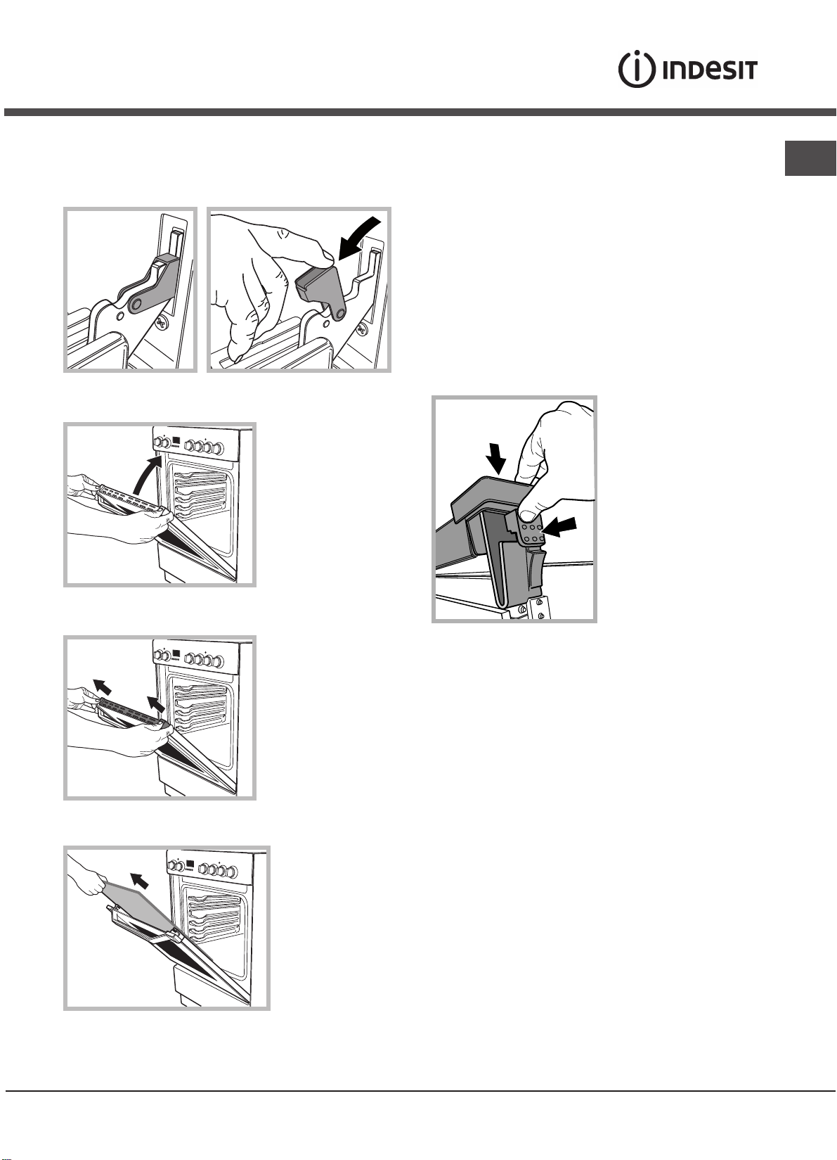
Removing and fitting the oven door:
1.Open the door
2.Make the hinge clamps of the oven door rotate
backwards completely (see photo)
40°
6.Replace the glass.
WARNING! Oven must not be operated
with inner door glass removed!
WARNING! When reassembling the inner
door glass insert the glass panel correctly
so that the text written on the panel is
not reversed and
7.Replace the profile, a click will indicate that the
part is positioned correctly.
8.Open the door completely.
9.Close the supports (see photo).
can be easily legible.
GB
3.Close the door until the clamps stop (the door will
remain open for 40° approx.) (see photo)
4.Press the two buttons on the upper profile and
10.Now the door can be completely closed and the
oven can be started for normal use.
extract the profile (see photo)
5.Remove the glass sheet and do the cleaning as
indicated in chapter: “Care and maintenance”.
21
GB
Steam-Assisted Oven Cleaning
This method of cleaning is recommended especially after
cooking very fatty (roasted)meats.
This cleaning process allows to facilitate the removal of
dirt of the walls of the oven by the generation of steam
that is created inside the oven cavity for easier cleaning.
! Important! Before you start steam -cleaning:
-Remove any food residue and grease from the bottom
of the oven.
- Remove any oven accessories (grids and drip pans).
Perform the above operations according to the following
procedure:
1. pour 300ml of water into the baking tray in the oven,
placing it in the bottom shelf. In the models where the
drip pan is not present, use a baking sheet and place it
on the grill at the bottom shelf;
2. select the function of the oven
and set the temperature to 100 ° C;
3. keep it in the oven for 15min;
4. turn off the oven;
5. Once cooled the oven, you can open the door to
complete the cleaning with water and a damp cloth;
6. eliminate any residual water from the cavity after
finishing cleaning
BOTTOM
When the steam –cleaning is done, after cooking
especially fatty foods, or when grease is difficult to
remove, you may need to complete the cleaning with the
traditional method, described in the previous paragraph.
! Perform cleaning only in the cold oven!
22
Instalacja
! Przed przystàpieniem do u˝ytkowania urzàdzenia, nale˝y
starannie zapoznaç si´ z podr´cznikiem u˝ytkownika. Zawiera on wa˝ne zalecenia dotyczàce bezpieczeƒstwa instalacji, obs∏ugi oraz konserwacji kuchenki. Podr´cznik nale˝y
zachowaç do póêniejszego u˝ytku.
! Instrukcj´ nale˝y zachowaç na przysz∏oÊç. Instrukcja musi byç do∏àczona do urzàdzenia w przypadku sprzeda˝y,
przekazywania innym osobom lub przeprowadzki.
! Poni˝sze instrukcje przeznaczone sà dla wykwalifikowanego specjalisty instalujàcego urzàdzenie. Instrukcje te majà
na celu zapewnienie mo˝liwie najbardziej profesjonalnego
i doÊwiadczonego wykonania czynnoÊci zwiàzanych z instalacjà i konserwacjà urzàdzenia.
! Wszelkie prace regulacyjne lub konserwacyjne nale˝y
przeprowadzaç po od∏àczeniu kuchenki od zasilania.
Wentylacja pomieszczenia
Wymagania dla pomieszczeƒ kuchennych
Przed przystàpieniem do instalowania kuchni gazowej
w pomieszczeniu kuchennym itp., nale˝y upewniç si´, czy
spe∏nia ono stawiane mu wymagania. Podstawa prawna,
w oparciu, o którà oceniamy przydatnoÊç pomieszczenia
do zainstalowania w nim kuchni gazowej, jest Rozporzàdzenie Ministra Gospodarki Przestrzennej i Budownictwa
z dnia 14 grudnia 1994 r. w sprawie warunków technicznych, jakim powinny odpowiadaç budynki i ich usytuowanie, b´dàce aktem wykonawczym do Prawa budowlanego
(Dz.U. nr 75 z dnia 16-12-2002 poz. 690).
Wa˝ne: niniejsze urzàdzenie mo˝e byç instalowane i wykorzystywane wy∏àcznie w pomieszczeniach z trwa∏à wentylacjà, zgodnie z obowiàzujàcymi przepisami
Pomieszczenie powinno umo˝liwiaç dop∏yw powietrza, które niezb´dne jest do w∏aÊciwego spalania gazu. Dop∏yw powietrza powinien byç nie mniejszy ni˝ 2 m
mocy palników. Powietrze mo˝e byç dostarczane w wyniku
bezpoÊredniego przep∏ywu z zewnàtrz przez kana∏ o prze-
2
kroju, co najmniej 100 cm
, którego konstrukcja musi uniemo˝liwiaç przypadkowe zablokowanie (Rysunek A). Otwór
ten nale˝y powi´kszyç o 100%, je˝eli instalacja kominowa
nie zosta∏a wyposa˝ona w urzàdzenie bezpieczeƒstwa, wykrywajàce ogieƒ. Ewentualnie dop∏yw powietrza mo˝e odbywaç si´ poÊrednio z sàsiednich pomieszczeƒ, które wyposa˝one sà w kana∏y wentylacyjne wychodzàce na zewnàtrz,
spe∏niajàce wymagania dla kana∏ów opisane powy˝ej.
Wszystko to przy za∏o˝eniu, ˝e sàsiednie pomieszczenia nie
sà pomieszczeniami wspólnymi, sypialniami ani nie wyst´puje w nich zagro˝enie po˝arowe (Rysunek B).
! JeÊli kuchnia jest wykorzystywana intensywnie I d∏ugo, to
mo˝e okazaç si´ konieczne otworzenie okna dla poprawienia wentylacji.
3
/h na jeden kW
Rysunek A
Przyk∏ady otworów
wentylacyjnych
pomieszczenie
sàsiednie
A
Rysunek B
Powi´kszenie szczeliny
wentylacyjnej pomi´dzy
oknem i pod∏ogà
pomieszczenie, które
ma byç wentylowane
Odprowadzanie spalin
Pomieszczenie, w którym ma byç zainstalowana kuchnia
powinno byç wyposa˝one w system wentylacji odprowadzajàcy na zewnàtrz spaliny powstajàce podczas spalania.
Instalacja ta powinna sk∏adaç si´ z okapu lub wentylatora
elektrycznego, który w∏àcza si´ automatycznie za ka˝dym
razem, gdy uruchamiana jest kuchnia.
komin lub rozga∏´ziony
kana∏ dymowy
bezpoÊrednio na zewnàtrz
(w przypadku kuchenek)
! Gaz p∏ynny jest ci´˝szy od powietrza i w zwiàzku z tym ma
tendencje do gromadzenia si´ na dolnych poziomach. Pokoje, w których zainstalowano butle z gazem p∏ynnym, powinny byç wyposa˝one w kana∏y wentylacyjne wyprowadzone z pomieszczenia na zewnàtrz, umo˝liwiajàce wydostawanie si´ gazu w przypadku nieszczelnoÊci. Z tego samego powodu butle z gazem, zarówno puste jak i cz´Êciowo nape∏nione, nie powinny byç ani instalowane, ani przechowywane w pomieszczeniach usytuowanych pod powierzchnià ziemi (piwnice, itp.). Dobrà praktykà jest przechowywanie w pomieszczeniu kuchennym jedynie tego
zbiornika, który jest aktualnie wykorzystywany, pod warunkiem, ˝e nie znajduje si´ on zbyt blisko êróde∏ ciep∏a (piecyki, kominki, piekarniki, itp.), które mog∏yby zwi´kszyç temperatur´ we wn´trzu zbiornika powy˝ej 50°C.
Ustawianie i poziomowanie kuchni
Kuchnia gazowa pod wzgl´dem ochrony przed przegrzaniem otaczajàcych powierzchni jest przyrzàdem klasy X i jako taka mo˝e byç zabudowana w ciàgu meblowym tylko do
wysokoÊci p∏yty roboczej tj. 850 mm od posadzki. Zabudowa powy˝ej tego poziomu jest zabroniona.
PL
23

PL
Uwaga: Kuchnia w klasie X nie mo˝e byç zabudowana wysokim meblem. Jednak w ka˝dym przypadku meble do zabudowy muszà mieç ok∏adzin´ oraz klej do jej przyklejenia
odporny na temperatur´ 100°C. Niespe∏nienie tego warunku mo˝e spowodowaç zdeformowanie powierzchni lub odklejenia ok∏adziny. Je˝eli nie mamy pewnoÊci, co do odpornoÊci termicznej mebli, kuchni´ nale˝y zabudowaç meblami zachowujàc odst´p ok. 2 cm.
! Âciana znajdujàca si´ za kuchnià powinna byç uodporniona na wysokie temperatury. Podczas korzystania z kuchni, jej
tylna Êciana mo˝e rozgrzaç si´ do temperatury oko∏o 90°C.
W∏aÊciwa instalacja kuchni wymaga uwzgl´dnienia
poni˝szych kwestii:
• Kuchni´ mo˝na zainstalowaç w kuchni, kuchnio-jadalni
lub pokoju spe∏niajàcym warunki techniczne wynikajàce
z przytoczonych przepisów; nie wolno jej instalowaç w ∏azience ani w pomieszczeniu z prysznicem.
• Meble znajdujàce si´ obok kuchni, które wystajà powy˝ej
powierzchni kuchni, powinny znajdowaç si´ w odleg∏oÊci,
co najmniej 200 mm od kraw´dzi p∏yty z palnikami.
• Szafki sàsiadujàce z okapem
powinny znajdowaç si´ w odleg∏oÊci, co najmniej 420 mm od
powierzchni kuchni. Minimalna
odleg∏oÊç nad poziomem palni-
mm. with hood
420
mm. without hood
650
700
ków, w jakiej mogà byç moco-
Min. mm.
min.
min.
wane elementy umeblowania
mm.
420
Min.
HOOD
Min. mm.
600
kuchni wykonane z materia∏ów
niezabezpieczonych termicznie
wynosi 700 mm.
• Nie stosowaç zas∏on z ty∏u kuchni i w odleg∏oÊci nie
mniejszej ni˝ 200 mm od jej boków.
• Okapy nale˝y montowaç zgodnie z instrukcjami podanymi w do∏àczonych do nich instrukcjach obs∏ugi, ale nie ni˝ej ni˝ 650 mm.
Kuchnia ma nast´pujàcà technicznà specyfikacj´:
Kat. II2ELs3B/P
Klasa 1
Klasa 2 podklasa 1
Monta˝ nó˝ek (niektóre modele)
Przyrzàd do montowania nó˝ek
w podstawie kuchni
Pod∏àczenie do instalacji elektrycznej
Kuchenki, które wyposa˝one sà w trójbiegunowy kabel zasilajàcy przystosowane sà do zasilania pràdem zmiennym
o parametrach podanych na tabliczce znamionowej
(umieszczonej we wn´ce pod piekarnikiem).
Uwaga: Do zasilania kuchni nie nale˝y stosowaç transformatorów, przejÊciówek ani boczników, gdy˝ mogà
si´ one nadmiernie nagrzewaç lub zapaliç.
Na kablu zasilajàcym nale˝y zamontowaç standardowà
wtyczk´, odpowiadajàcà maksymalnemu obcià˝eniu, które
podano na tabliczce znamionowej. Ewentualnie, pod∏àczyç
urzàdzenie bezpoÊrednio do instalacji elektrycznej. W tym
przypadku nale˝y dodatkowo zamontowaç jednobiegunowy
wy∏àcznik sieciowy o odleg∏oÊci styków, co najmniej 3 mm
i odpowiadajàcy obowiàzujàcym przepisom bezpieczeƒstwa
(przewód uziemiajàcy nie mo˝e byç roz∏àczany przez wy∏àcznik). Wy∏àcznik ten b´dzie odcina∏ kuchenk´ od zasilania. Kabel zasilajàcy powinien byç u∏o˝ony w taki sposób, aby temperatura w ˝adnym punkcie jego powierzchni nie mog∏a
przekroczyç temperatury pokojowej powi´kszonej o 50°C.
Przed wykonaniem po∏àczenia nale˝y sprawdziç czy:
• Urzàdzenie posiada obwód ochronny i wtyczk´ zgodnà
z obowiàzujàcymi przepisami.
• Bezpiecznik oraz instalacja elektryczna wytrzymajà obcià˝enie kuchenki.
• Instalacja elektryczna wyposa˝ona jest w skuteczny system uziemiajàcy spe∏niajàcy wymagania aktualnych standardów i przepisów.
! Wtyczka lub wy∏àcznik sieciowy muszà byç ∏atwo dost´pne po zainstalowaniu kuchenki.
! Przewód zasilajàcy nie mo˝e byç zagi´ty lub przygnieciony.
! Przewód zasilajàcy musi byç regularnie sprawdzany i w ra-
zie usterki wymieniony przez autoryzowanego technika.
! Producent nie ponosi ˝adnej odpowiedzialnoÊci za
ewentualne szkody wynik∏e z niew∏aÊciwego zainstalowania urzàdzenia.
Poziomowanie kuchni
24
Kuchenka wyposa˝ona jest w nó˝ki o zmiennej wysokoÊci umo˝liwiajàce odpowiednie wypoziomowanie urzàdzania. JeÊli jest to konieczne nale˝y wkr´ciç lub wykr´ciç
nó˝ki znajdujàce si´ w naro˝nikach
podstawy kuchenki a˝ do uzyskania w∏aÊciwego wypoziomowania.
Pod∏àczenie gazu do kuchni
Uwaga: CzynnoÊç ta mo˝e byç wykonana jedynie przez
technika z odpowiednimi uprawnieniami, autoryzowanego przez producenta.
Pod∏àczyç kuchni´ do butli gazowej lub rury instalacji gazowej, przestrzegajàc obowiàzujàcych przepisów, wy∏àcznie po
uprzednim ustaleniu, czy kuchnia mo˝e byç zasilana gazem
wyst´pujàcym w danej instalacji. JeÊli jest inaczej, nale˝y wy-
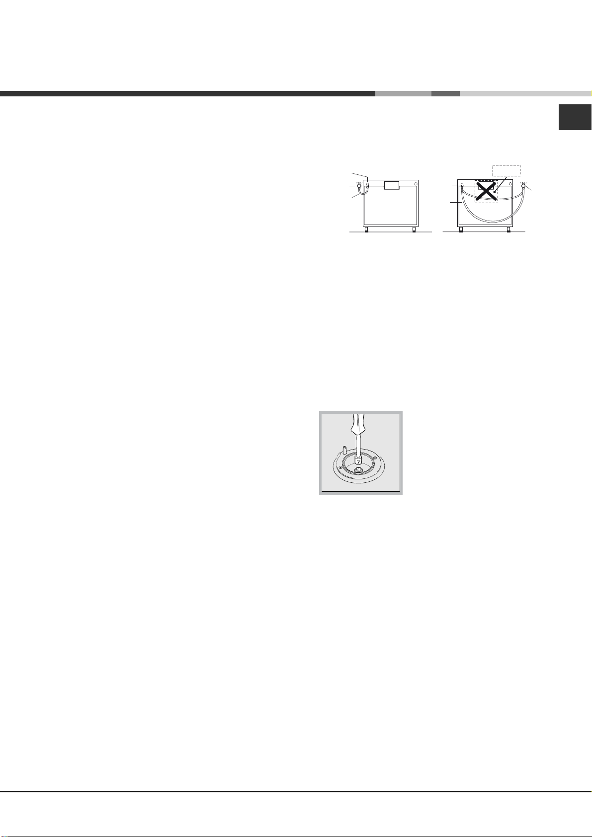
konaç zalecania podane w cz´Êci „Dostosowywanie kuchenki do ró˝nych rodzajów gazów”. Niektóre modele kuchenki
umo˝liwiajà pod∏àczenie instalacji gazowej z lewej lub prawej
strony kuchenki – aby zmieniç stron´ zasilania nale˝y zamieniç po∏o˝enie uchwytu w´˝a i korka zamykajàcego oraz wymieniç uszczelk´ (do∏àczonà do kuchni). W przypadku pod∏àczenia do butli z gazem p∏ynnym nale˝y zastosowaç regulator ciÊnienia, spe∏niajàcy obowiàzujàce przepisy.
Wa˝ne: nale˝y sprawdziç czy ciÊnienie gazu w instalacji
zgodne jest z zaleceniami podanymi w tabeli 1 zatytu∏owanej „Parametry dysz i palników”. Zapewni to bezpiecznà
prac´ kuchni, w∏aÊciwe zu˝ycie gazu oraz przed∏u˝y czas
bezawaryjnej pracy kuchni.
Pod∏àczenie do sztywnej instalacji rurowej
(miedzianej lub stalowej)
Pod∏àczenie do instalacji gazowej powinno byç wykonane
w taki sposób, który nie wywo∏uje napr´˝eƒ w ˝adnym
punkcie instalacji ani na ˝adnej cz´Êci urzàdzenia.
Urzàdzenie wyposa˝one jest w regulowanà z∏àczk´
w kszta∏cie litery “L” oraz uszczelk´, które umo˝liwiajà pod∏àczenie do instalacji gazowej. Je˝eli zajdzie potrzeba przekr´cenia z∏àczki to wymagana b´dzie równie˝ wymiana
uszczelki (do∏àczonej do urzàdzenia).
Z∏àcze doprowadzajàce gaz do kuchenki to m´ski cylinder
z gwintem 1/2.
Pod∏àczenie do elastycznego przewodu metalowego
Z∏àcze doprowadzajàce gaz do kuchenki to z∏àcze m´skie
z gwintem 1/2 do rur gazowych o przekroju okràg∏ym. Do
pod∏àczenia nale˝y stosowaç wy∏àcznie rury i uszczelki odpowiadajàce aktualnie obowiàzujàcym normom. Maksymalna d∏ugoÊç przewodu elastycznego nie mo˝e przekraczaç 2000 mm. Po wykonaniu po∏àczenia nale˝y sprawdziç
czy elastyczny przewód metalowy nie styka si´ z ˝adnymi
cz´Êciami ruchomymi ani czy nie jest niczym przyciÊni´ty.
Pod∏àczenie w´˝em elastycznym
Kuchni´ gazowà pod∏àczamy w´˝em elastycznym tylko
w przypadku zasilania gazem p∏ynnym z butli gazowej.
Do pod∏àczenia nale˝y zastosowaç wà˝ gazowy odpowiadajàcy wymaganiom okreÊlonym przez krajowe normy. JeÊli kuchenka zasilana jest gazem p∏ynnym nale˝y zastosowaç regulatory ciÊnienia, które spe∏niajà krajowe przepisy
techniczne. Wewn´trzna Êrednica w´˝a powinna wynosiç:
• 8 mm, w przypadku zasilania gazem p∏ynnym
Sprawdziç czy wà˝ jest ÊciÊle dopasowany na obu koƒcach.
Do zamocowania w´˝a u˝yç standardowych zacisków,
G∏ównymi postanowienia obowiàzujàcych norm technicznych przewidujà, ˝e:
• wà˝ nie powinien w ˝adnym punkcie stykaç si´ z „goràcy-
mi” elementami kuchenki;
• wà˝ nie powinien byç d∏u˝szy ni˝ 1,5 metra
• wà˝ nie powinien byç w ˝adnym miejscu zgi´ty ani naciàgni´ty, na ca∏ej swojej d∏ugoÊci nie powinien równie˝ posiadaç ciasnych zakr´tów ani zw´˝eƒ
• na ca∏ej swojej d∏ugoÊci wà˝ powinien byç dost´pny, tak,
aby mo˝liwa by∏a kontrola jego zu˝ycia
• w przypadku wykrycia nieszczelnoÊci wà˝ powinien byç
ca∏kowicie wymieniony; naprawianie nieszczelnego w´˝a
jest zabronione
Punkt przyłączenia
Kurek zamykający
Położenie węża
Punkt przyłączenia
Położenie węża
GORĄCA
POWIERZCHNIA
Kurek zamykający
Sprawdzanie szczelnoÊci
Wa˝ne: Po zakoƒczeniu instalacji kuchenki nale˝y sprawdziç szczelnoÊç wszystkich po∏àczeƒ stosujàc do tego wod´ z myd∏em. Do sprawdzania szczelnoÊci nie wolno w ˝adnym wypadku stosowaç ognia!
Dostosowywanie kuchenki
do ró˝nych rodzajów gazów
Aby dostosowaç kuchenk´ do gazu innego rodzaju, ni˝ rodzaj, dla którego zaprojektowano kuchenk´ (patrz naklejka
na spodzie kuchenki lub na opakowaniu), nale˝y wymieniç
dysze palników, zgodnie z poni˝szà procedurà:
1. Zdemontowaç krat´ podpierajàcà garnki i wysunàç palniki z kuchenki
2. Za pomocà klucza nasadowego
7mm odkr´ciç dysze i wymieniç je
na nowe dysze, odpowiednie do
gazu danego typu (patrz Tabela 1,
„Parametry dysz i palników”).
3. Ponownie zmontowaç razem cz´Êci, wykonujàc wy˝ej opisane
czynnoÊci w odwrotnej kolejnoÊci
Regulacja dop∏ywu powietrza do palnika
Palniki nie wymagajà takiej regulacji.
Regulacja minimalnej wielkoÊci p∏omienia
1. Ustawiç zawór gazu w po∏o˝eniu najmniejszego p∏omienia
2. Zdemontowaç pokr´t∏o i przekr´ciç Êrub´ regulacyjnà
(znajdujàcà si´ bàdê po jednej ze stron trzonka lub w jego Êrodku). Przekr´ciç Êrub´ w kierunku zgodnym z ruchem wskazówek zegara do po∏o˝enia, w którym p∏omieƒ b´dzie ma∏y i stabilny.
3. Sprawdziç czy p∏omieƒ nie gaÊnie podczas szybkiego
kr´cenia zaworem
4. W przypadku niew∏aÊciwego dzia∏ania kuchenek wypo-
sa˝onych w urzàdzenie zabezpieczajàce (termoelement)
!
przy ustawieniu najmniejszego p∏omienia, nale˝y zwi´kszyç
wielkoÊç p∏omienia za pomocà Êruby.
!
W przypadku zasilania gazem p∏ynnym, Êruba regulacyj-
!
na powinna byç ca∏kowicie wkr´cona do samego koƒca.
Po zakoƒczonej regulacji, nale˝y zmieniç nalepk´ z opi-
sem rodzaju gazu, do jakiego kuchnia jest przystosowana.
JeÊli ciÊnienie gazu w instalacji ró˝ni si´ od wartoÊci, podanych w niniejszej instrukcji, nale˝y zastosowaç regulator
ciÊnienia.
PL
25
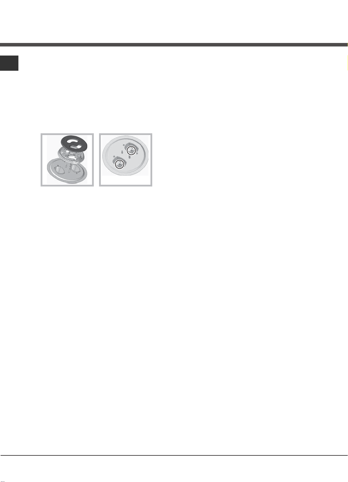
PL
:\PLDQDG\V]ZSDOQLNX3RWUoMQD.RURQD
=GHPRQWXMUXV]W\LZ\VXÇSDOQLN]S¦\W\3DOQLN
VN¦DGDVL¿]RGU¿EQ\FKF]¿ÑFLSDWU]U\VXQHN
SRQLÝHM
=D SRPRFºVSHFMDOQHJR NOXF]D QDVDGRZHJR PP
Z\NU¿²G\V]H:\PLHÇG\V]HQDQRZHRGSRZLHGQLH
GODJD]XQRZHJRW\SXSDWU]7DEHOD2ELHG\V]H
PDMºRWZRU\RMHGQDNRZHMÑUHGQLF\
=¦oÝSDOQLN]SRZURWHPZ\NRQXMºFSRZ\ÝV]H
F]\QQRÑFLZ RGZUoFRQHM NROHMQRÑFL
5HJXODFMDSRZLHWU]DSLHUZRWQHJRSDOQLNQLH
Z\PDJDUHJXODFMLSRZLHWU]D
5HJXODFMDPLQLPDOQHMZLHONRÒFLS¦RPLHQLD
8VWDZ]DZoUJD]XZSR]\FMLQDMPQLHMV]HJR
S¦RPLHQLD
=GHPRQWXMSRNU¿W¦RL SU]HNU¿FDM ÑUXE¿UHJXODF\MQº
]QDMGXMºFºVL¿SRMHGQHM]HVWURQWU]RQNDOXEZMHJR
ÑURGNXDÝGRPRPHQWXJG\S¦RPLHÇE¿G]LHPD¦\DOH
UoZQ\
3R]DNRÇF]HQLXUHJXODFMLSU]\]DSDORQ\PSDOQLNX
SU]HVWDZNLONXNURWQLHV]\ENLPUXFKHPSRNU¿W¦R]SR]\FML
PLQLPXPGR PDNVLPXP L RGZURWQLH VSUDZG]DMºF F]\
S¦RPLHÇQLH JDÑQLH
1LHNWoUHPRGHOHNXFKQLZ\SRVDÝRQHVºZXU]ºG]HQLD
]DEH]SLHF]DMºFHWHUPRSDU\-HÝHOL]DEH]SLHF]HQLHQLH
E¿G]LHG]LD¦D² QD PLQLPDOQ\P XVWDZLHQLX SDOQLND
]ZL¿NV]S¦RPLHÇSU]HNU¿FDMºF ÑUXE¿ UHJXODF\MQº
3R]DNRÇF]HQLXUHJXODFMLQDOHÝ\Z\PLHQL²XV]F]HONL
QDSU]HZRGDFKLXV]F]HOQL²
*
26
* Dost´pne w niektórych modelach.
 Loading...