


I5GG /U
GB
English
Operating Instructions
COOKER AND OVEN
Contents
Operating Instructions,1
Description of the appliance-Overall view,2
Description of the appliance-Control Panel,3
Installation,4
Start-up and use,8
Cooking modes,9
Precautions and tips,10
Care and maintenance,12
Assistance,12
Polski
PL
Instrukcja obsługi
KUCHENKA I PIEKARNIK
LV
Latviešu
Lietođanas instrukcija
PLÎTS UN KRASNS
Saturs
Lietođanas instrukcija,1
Ierîces apraksts -Vispârîga informâcija,2
Ierîces apraksts - Vadîbas panelis,3
Uzstâdîđana,32
Leslçgđana un lietođana,36
Cepeđkrâsns lietođana,36
Piesardzîbas pasâkumi un ieteikum,38
Tehniskâ apkope un kopđana,39
Palîdzîba,39
Eesti keeles
EE
Kasutusjuhend
PLIIT JA AHI
Spis treści
Instrukcja obsługi,1
Opis urządzenia-Widok ogólny,2
Opis urządzenia-Panel sterowania,3
Instalacja,13
Uruchomienie i użytkowanie,17
Użytkowanie piekarnika,17
Zalecenia i środki ostrożności,19
Konserwacja i utrzymanie,20
Serwis Techniczny,20
LT
Lietuviu
Naudojimo instrukcijos
viryklë ir orkaitë
Turinys
Naudojimo instrukcijos,1
Prietaiso aprašymas -Bendras vaizdas,2
Prietaiso aprašymas -Valdymo pultas,3
Montavimas,22
Ájungimas ir naudojimas,26
Orkaitës naudojimas,26
Atsargumo priemonës ir patarimai,29
Techninë prieţiűra,30
Pagalba,30
Sisukord
Kasutusjuhend,1
Seadme kirjeldus - Ülevaade,2
Seadme kirjeldus - Juhtpaneel,3
Paigaldamine,41
Esmakäitamine ja kasutamine, 45
Ahju kasutamine,47
Ettevaatusabinőud ja soovitused, 47
Hooldus,48
Klienditugi,48
14
LT
1.Dujų degiklis
2. Kaitlentès tinklelis
1
2
3
4
5
6
7
8
9
10
11
12
13
6
3.Valdymo pultas
4.KEPSNINÈ
5.SURINKIMO INDAS
6. Reguliuojamoji kojelè (Yra tik tam tikruose modeliuose)
7. TIškalų sulaikymo paviršius
8.Slankiųjų grotelių TAKELIAI
9. padètis 5
10.padètis 5
11.padètis 5
12. padètis 5
13. padètis 5
14.Stiklinis gaubtas
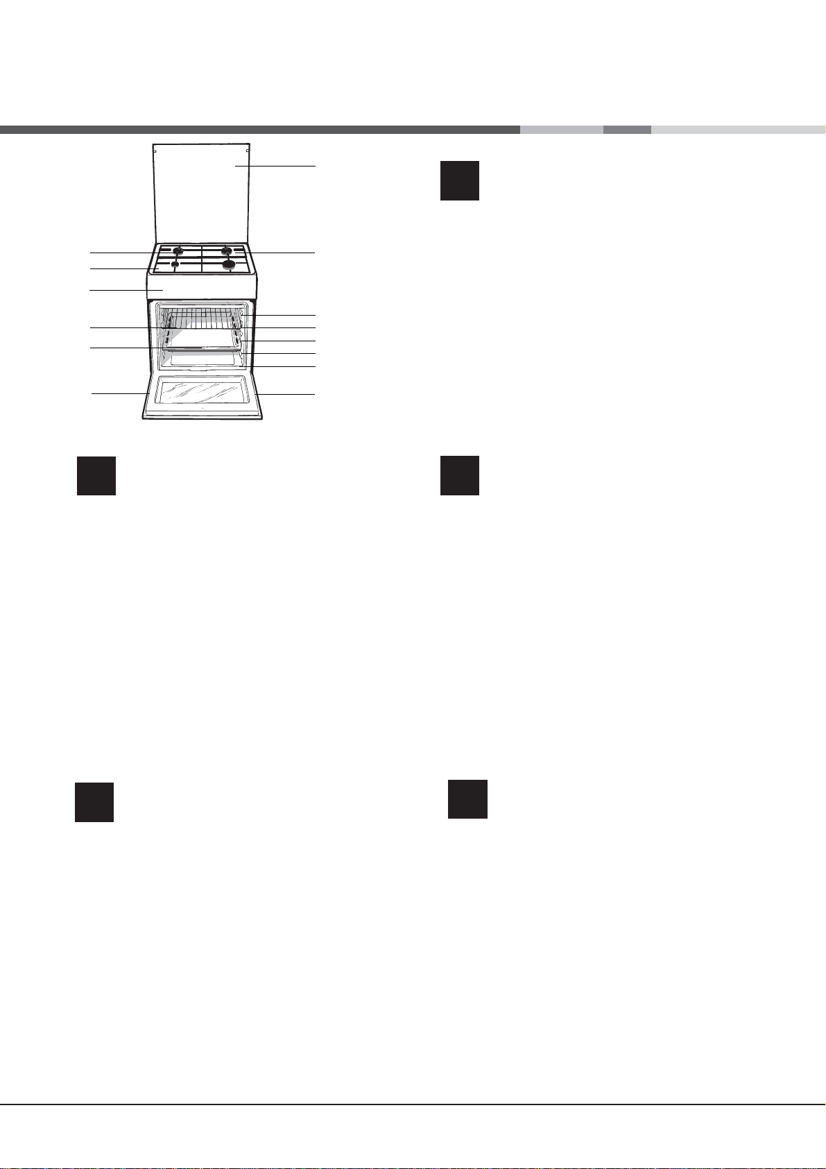
Prietaiso aprađymas
Bendras vaizdas
GB
1.Hob burner
2 Hob Grid
3.Control panel
4.Sliding grill rack
5.DRIPPING pan
6.Adjustable foot
7.Containment surface for spills
8.GUIDE RAILS for the sliding racks
9.position 5
10.position 4
11.position 3
12.position 2
13.position 1
14/ Glass Cover *(Available only on certain
models)
Description of the appliance
Overall view
Opis urządzenia
PL
Widok ogólny
1. Palnik gazowy
2.Ruszta płyty podpalnikowej
3.Panel kontrolny
4.Półka ruszt
5.Półka brytfanna
6.Nóżki regulowane
7. Płyta podpalnikowa
8.Prowadnice półek
9.pozycja 5
10.pozycja 4
11.pozycja 3
12.pozycja 2
13.pozycja 1
14.Szklana pokrywa (Tylko w niektórych modelach)
LV
1.Gćzes deglis
2.Plīts virsmas režģisģ
3.STIKLA KERAMIKAS VIRSMA
4.Vadības panelis
5.CEPE TAUKU PANNA
6.Regulējama kāja
7 Norobe˛ota virsma traipiem
8.VADOTNES slīdošo pamatņu ievietošanai un izņemšanai
9. pozīcija 5
10.pozīcija 4
11.pozīcija 3
12.pozīcija 2
13.pozīcija 1
14. Stikla pārsegs (Pieejams tikai noteiktiem modeļiem)
1.Gaasipõleti
2.Rest
3.Juhtpaneel
4.GRILL
5.TILGAPANN
6.Reguleerimisjalg
7.Tilgaalus
8.SIINID restide sisestamiseks
9. tasand 5
10. tasand 4
11.tasand 3
12.tasand 2
13.tasand 1
14 klaaskate (Ainult mőnedel mudelitel)
Ierîces apraksts
Vispariga informacija
Seadme kirjeldus
EE
Ülevaade
2
2
GB
1
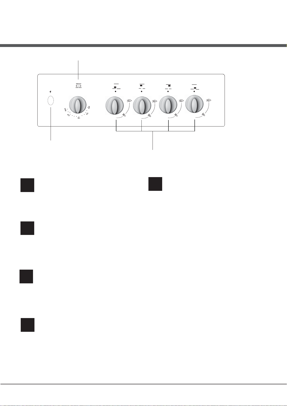
Description of the appliance
GB
1.GAS BURNER IGNITION button
2.THERMOSTAT knob
3.Hob BURNER control knob
PL
Control panel
Opis urządzenia
Panel kontrolny
I
I
I
I
I
I
I
I
III
I
III
I
3
Seadme kirjeldus
EE
Juhtpaneel
1.GAASIPÕLETI süütenupp
2.TERMOSTAADI nupp
3.PÕLETITE reguleernupp
1.ZAPALARKA palników płyty
2.Pokrętło TERMOSTATU
3.Pokrętło PALNIKÓW PŁYTY GRZEJNEJ
Prietaiso aprađymas
LT
1.Elektroninis kaitlentčs degikilř apšvietimas
2.TERMOSTATO rankenčlč
3.Kaitlentčs dujř degikilř valdymo rankenčlčs
Valdymo pultas
Ierîces apraksts
LV
1.GĀZES DEGĻA iedegšanas poga
2.TERMOSTATA slēdzis
3.DEGĻA vadības slēdzi
Vispariga informacija
3
Installation
HOOD
420
Min.
min.
650
mm. with hood
min.
700
mm. without hood
mm.
600
Min. mm.
420
Min. mm.
GB
! Before operating your new appliance please read
this instruction booklet carefully. It contains important
information concerning the safe installation and
operation of the appliance.
! Please keep these operating instructions for future
reference. Make sure that the instructions are kept with
the appliance if it is sold, given away or moved.
! The appliance must be installed by a qualified
professional according to the instructions provided.
! Any necessary adjustment or maintenance must be
performed after the cooker has been disconnected
from the electricity supply.
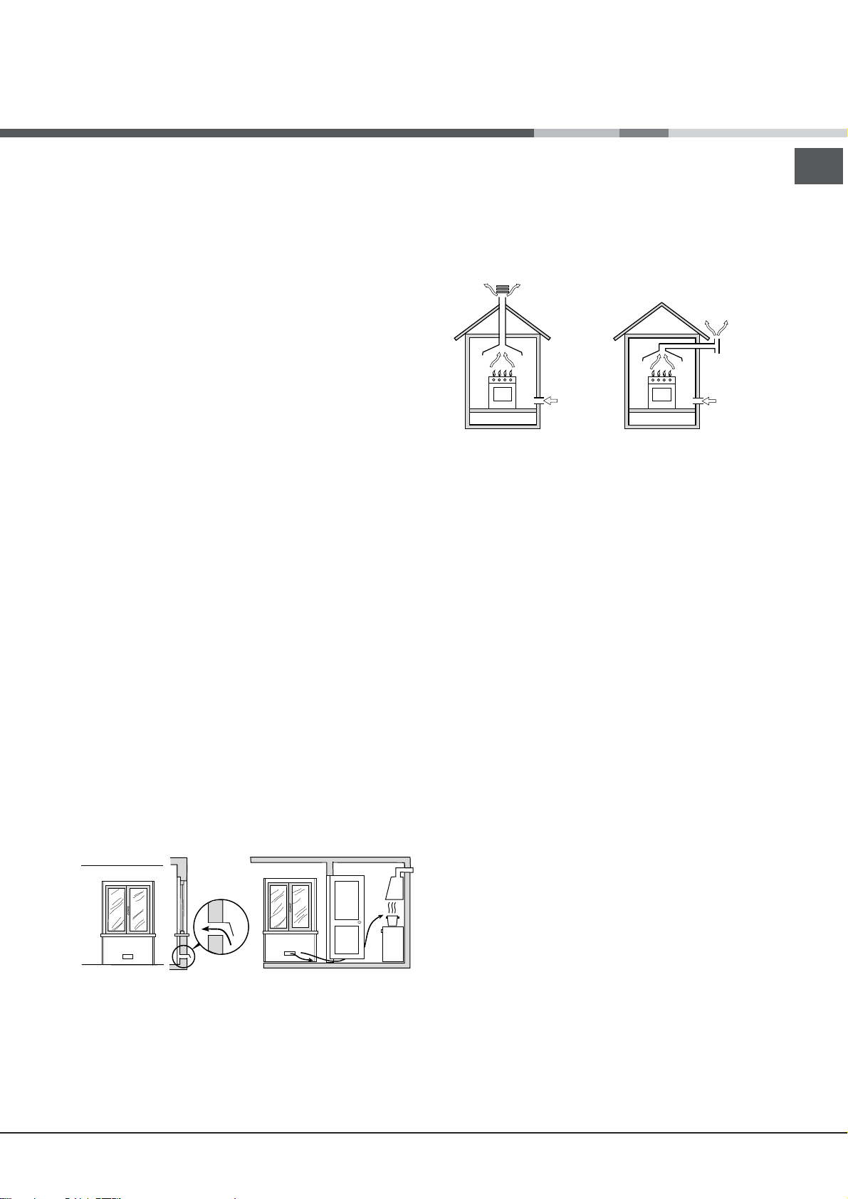
Room ventilation
The appliance may only be installed in permanentlyventilated rooms, according to current national
legislation. The room in which the appliance is installed
must be ventilated adequately so as to provide as
much air as is needed by the normal gas combustion
process (the flow of air must not be lower than 2 m
per kW of installed power).
The air inlets, protected by grilles, should have a duct
with an inner cross section of at least 100 cm
2
should be positioned so that they are not liable to even
partial obstruction (see gure A).
These inlets should be enlarged by 100% - with a
2
minimum of 200 cm
- whenever the surface of the
hob is not equipped with a flame failure safety device.
When the flow of air is provided in an indirect manner
from adjacent rooms (see gure B), provided that these
are not communal parts of a building, areas with
increased fire hazards or bedrooms, the inlets should
be fitted with a ventilation duct leading outside as
described above.
A B
A
Ventilation opening for
comburent air
Adjacent room Room requiring
ventilation
Increase in the gap between
the door and the flooring
! After prolonged use of the appliance, it is advisable to
open a window or increase the speed of any fans used.
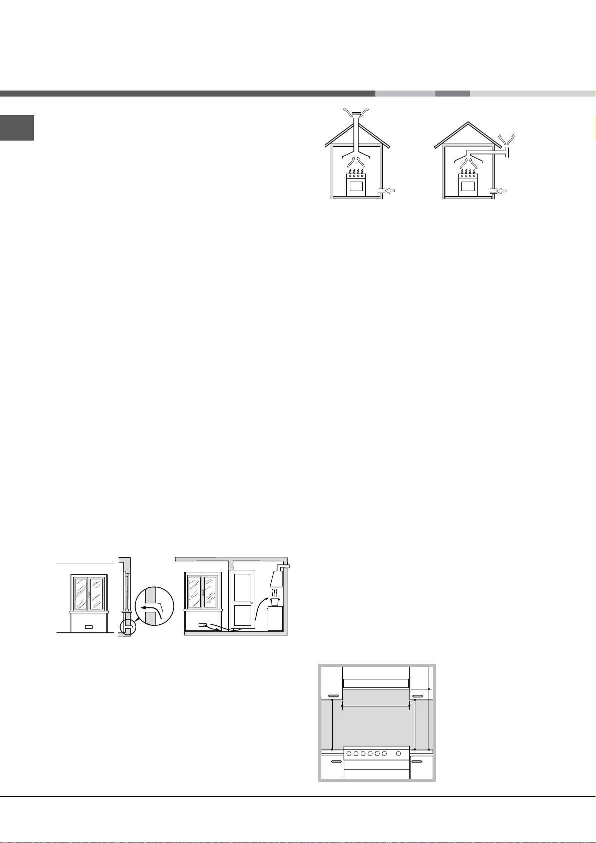
Disposing of combustion fumes
The disposal of combustion fumes should be
guaranteed using a hood connected to a safe and
efficient natural suction chimney, or using an electric
fan that begins to operate automatically every time the
appliance is switched on (see gure).
4
and
Fumes channelled
straight outside
Fumes channelled through
a chimney or branched
flue system reserved for
cooking appliances)
! The liquefied petroleum gases are heavier than air
and collect by the floor, therefore all rooms containing
LPG cylinders must have openings leading outside so
that any leaked gas can escape easily.
LPG cylinders, therefore, whether partially or
completely full, must not be installed or stored in rooms
or storage areas that are below ground level (cellars,
etc.). Only the
3
/h
cylinder being used should be stored in the room; this
should also be kept well away from sources
of heat (ovens, chimneys, stoves) that may cause
the temperature of the cylinder to rise above 50°C.
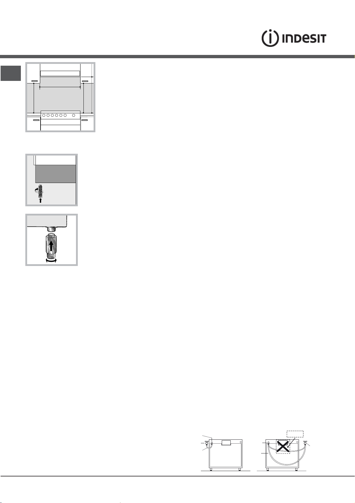
Positioning and levelling
! It is possible to install the appliance alongside
cupboards whose height does not exceed that of the
hob surface.
! Make sure that the wall in contact with the back of
the appliance is made from a non-flammable, heatresistant material (T 90°C).
To install the appliance correctly:
• Place it in the kitchen, dining room or the bed-sit (not
in the bathroom).
• If the top of the hob is higher than the cupboards,
the appliance must be installed at least 200 mm away
from them.
• If the cooker is installed underneath a wall cabinet,
there must be a minimum distance of 420 mm
between this cabinet and the top of the hob.
This distance should be increased to 700 mm if the
wall cabinets are flammable (see gure).
• Do not position blinds behind the cooker or less than
200 mm away from its
sides.
• Any hoods must be
installed according to
the instructions listed in
the relevant operating
manual.
Levelling
If it is necessary to level
the appliance, screw the adjustable feet into the places
provided on each corner of the base of the cooker (see
gure).
The legs* fit into the slots on the
underside of the base of the
cooker.
* Only available in certain models
Electrical connection
Install a standardised plug
indicated on the appliance data
plate (see Technical data table).
The appliance must be directly connected to the mains
using an omnipolar circuit-breaker with a minimum contact
opening of 3 mm installed between the appliance and the
mains. The circuit-breaker must be suitable for the charge
indicated and must comply with NFC 15-100 regulations
(the earthing wire must not be interrupted by the circuitbreaker). The supply cable must be positioned so that it
does not come into contact with temperatures higher than
50°C at any point.
Before connecting the appliance to the power supply,
make sure that:
• The appliance is earthed and the plug is compliant with
the law.
• The socket can withstand the maximum power of the
appliance, which is indicated by the data plate.
• The voltage is in the range between the values
indicated on the data plate.
• The socket is compatible with the plug of the
appliance. If the socket is incompatible with the
plug, ask an authorised technician to replace it. Do
not use extension cords or multiple sockets.
corresponding to the load
Gas connection
GB
Connection to the gas network or to the gas cylinder
may be carried out using a flexible rubber or steel hose,
in accordance with current national legislation and after
making sure that the appliance is suited to the type of gas
with which it will be supplied (see the rating sticker on
the cover: if this is not the case see below). When using
liquid gas from a cylinder, install a pressure regulator
which complies with current national regulations. To
make connection easier, the gas supply may be turned
sideways*: reverse the position of the hose holder with
that of the cap and replace the gasket that is supplied
with the appliance.
! Check that the pressure of the gas supply is
consistent with the values indicated in the Table
of burner and nozzle specifications (see below).
This will ensure the safe operation and durability of
your appliance while maintaining efficient energy
consumption.
Gas connection using a flexible rubber hose
Make sure that the hose complies with current national
legislation. The internal diameter of the hose must
measure: 8 mm for liquid gas supply; 13 mm for
methane gas supply.
Once the connection has been performed, make sure
that the hose:
• Does not come into contact with any parts that reach
temperatures of over 50°C.
• Is not subject to any pulling or twisting forces and
that it is not kinked or bent.
• Does not come into contact with blades, sharp
corners or moving parts and that it is not
compressed.
• Is easy to inspect along its whole length so that its
condition may be checked.
• Is shorter than 1500 mm.
• Fits firmly into place at both ends, where it will
be fixed using clamps that comply with current
regulations.
! Once the appliance has been installed, the power
supply cable and the electrical socket must be easily
accessible.
! The cable must not be bent or compressed.
! The cable must be checked regularly and replaced
by authorised technicians only.
! The manufacturer declines any liability should
these safety measures not be observed.
! If one or more of these conditions is not fulfilled
or if the cooker must be installed according to the
conditions listed for class 2 - subclass 1 appliances
(installed between two cupboards), the flexible steel
hose must be used instead (see below).
5
GB
A
V
Connecting a flexible jointless stainless steel pipe to
a threaded attachment
Make sure that the hose and gaskets comply with
current national legislation.
To begin using the hose, remove the hose holder on the
appliance (the gas supply inlet on the appliance is a
cylindrical threaded 1/2 gas male attachment).
! Perform the connection in such a way that the hose
length does not exceed a maximum of 2 metres,
making sure that the hose is not compressed and does
not come into contact with moving parts.
! The hob burners do not require primary air
adjustment.
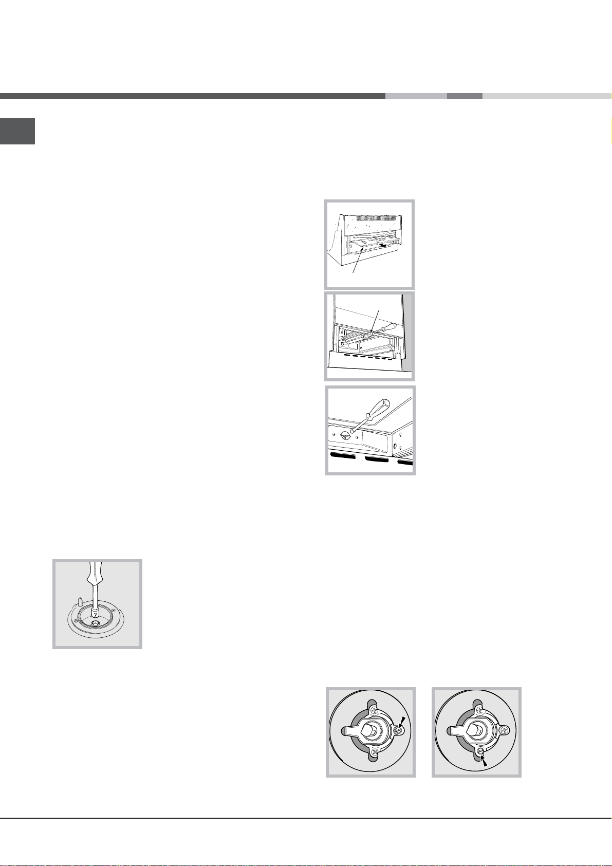
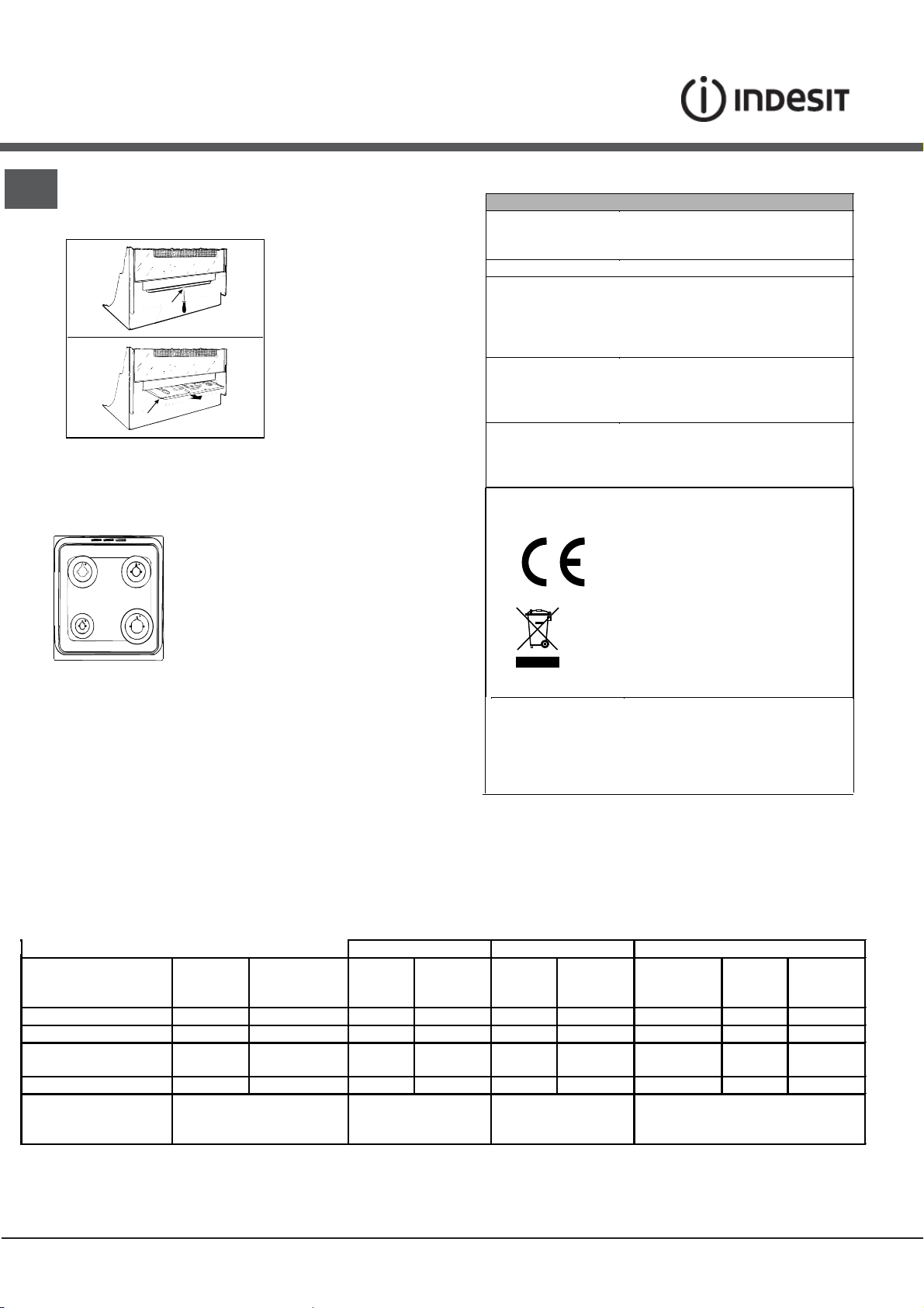
Adapting the oven
Replacing the oven burner nozzle:
1. Remove the oven compartment.
2. Slide out the protection panel A
(see diagram).
3. Remove the oven burner
after unscrewing the screws V
(see gure).
The whole operation will be
made easier if the oven door is
removed.
Checking the connection for leaks
When the installation process is complete, check the
hose fittings for leaks using a soapy solution. Never
use a flame.
Adapting to different types of gas
It is possible to adapt the appliance to a type of gas
other than the default type (this is indicated on the
rating label on the cover).
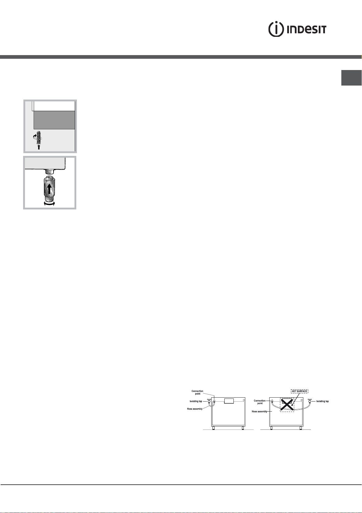
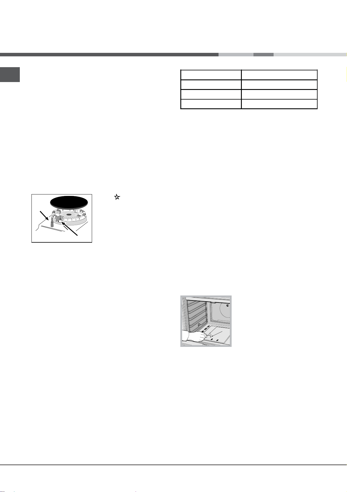
Adapting the hob
Replacing the nozzles for the hob burners:
1. Remove the hob grids and slide the burners off their
seats.
2. Unscrew the nozzles using a 7 mm socket spanner
(see gure), and replace them with nozzles suited to
the new type of gas(see Burner and nozzle speci cations
table).
3. Replace all the components by following the above
instructions in reverse.
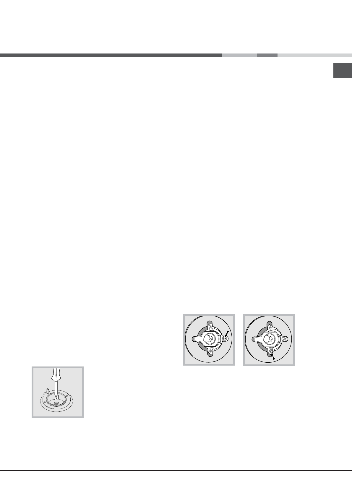
Adjusting the hob burners’
minimum setting:
1. Turn the tap to the minimum
position.
2. Remove the knob and adjust
the regulatory screw, which is
positioned inside or next to the tap pin, until the flame
is small but steady.
! If the appliance is connected to a liquid gas supply,
the regulatory screw must be fastened as tightly as
possible.
3. While the burner is alight, quickly change the position of
the knob from minimum to maximum and vice versa several
times, checking that the flame is not extinguished.
4. Unscrew the nozzle using a
special nozzle socket spanner
(see gure) or with a 7 mm
socket spanner, and replace it
with a new nozzle that is suited
to the new type of gas (see
Burner and nozzle speci cations
Adjusting the gas oven
burner’s minimum setting:
1. Light the burner (see Start-up
and Use).
table).
2. Turn the knob to the
minimum position (MIN) after it has been in the
maximum position (MAX) for approximately 10 minutes.
3. Remove the knob.
4. Tighten or loosen the adjustment screws on the
outside of the thermostat pin (see gure) until the flame
is small but steady.
! If the appliance is connected to liquid gas, the
adjustment screw must be fastened as tightly as
possible.
5. Turn the knob from the MAX position to the MIN
position quickly or open and shut the oven door,
making sure that the burner is not extinguished.
6
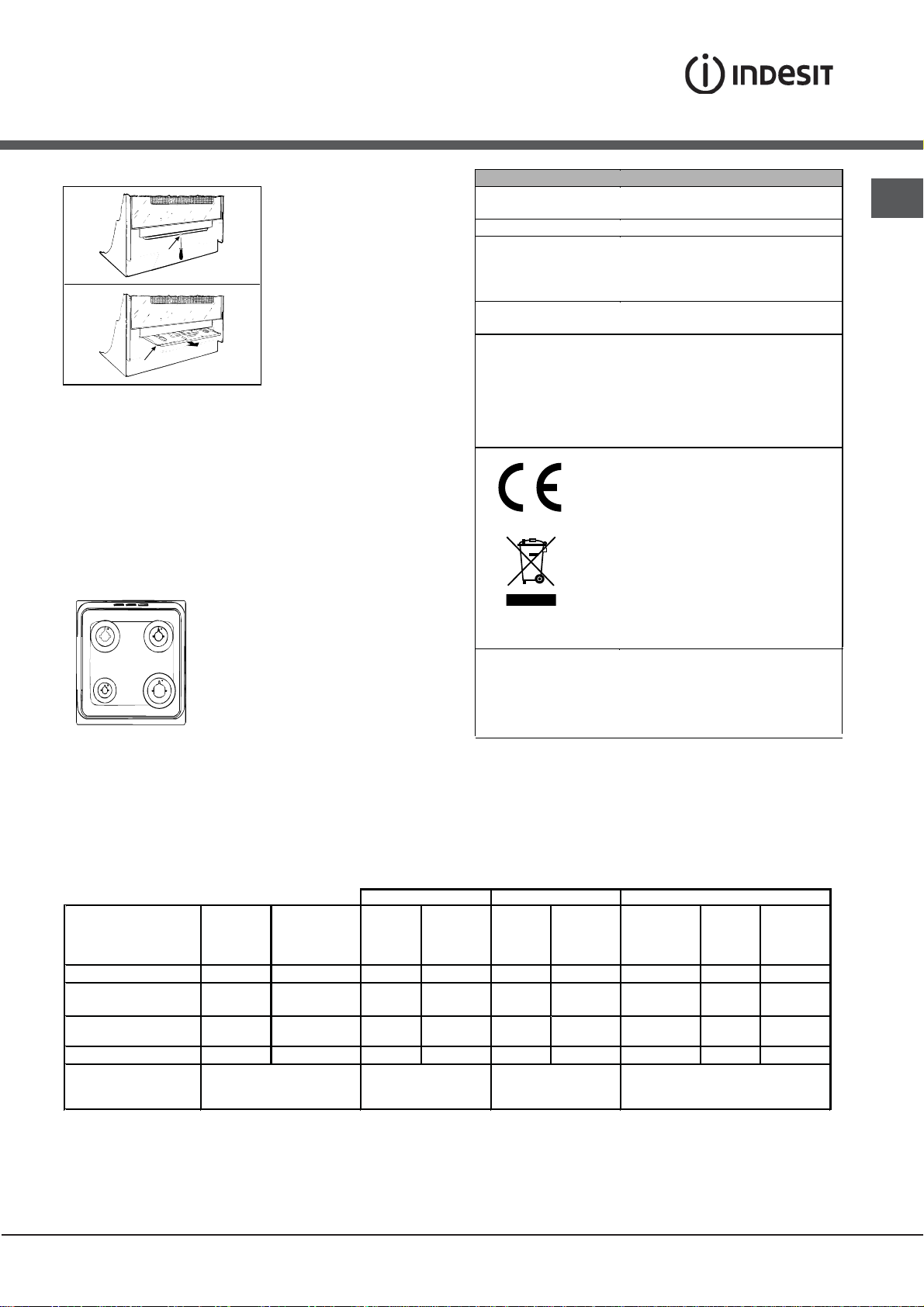
S
S
R
A
WARNING
S
A
To remove the sliding protection “A”, unscrew screw
“S”. When you have finished, replace the protection
and lock it in place with screw “S”.
Before using the oven, make sure the sliding protection
“A” is fastened in the correct position.
I5GG /U
TECHNICAL DATA
Oven dimensions
(HxWxD)
Volume
Useful
measurements
relating to the oven
compartment
Power supply voltage
and frequency
Burners
ENERGY LABEL
and ECODESIGN
34x39x 44 cm
58 l
width 42 cm
depth 44 cm
height 18 cm
see data plate
may be adapted for use with any
type of gas shown on the data
plate, which is located inside the
flap or, after the oven
compartment has been opened,
on the left-hand wall inside the
oven.
EC Directives: 2006/95/EC dated
12/12/06 (Low Voltage) and
subsequent amendments 2004/108/EC dated 15/12/04
(Electromagnetic Compatibility)
and subsequent amendments 90/396/EEC dated 29/06/90 (Gas)
and subsequent amendments 93/68/EEC dated 22/07/93 and
subsequent amendments 2002/96/EC.
Regulation (EU) No 65/2014 supplementing Directive 2010/30/EU.
Regulation (EU) No 66/2014 implementing
Directive 2009/125/EC.
Standard EN 30-2-1
Standard EN 15181.
GB
Table of burner and nozzle specifications
Table 1 (for Poland) G20 (GZ50) G2.350 (GZ35) G30 (GPB)
Burner Diameter
Fast (Large)(R)
Semi Fast
(Medium)(S)
Auxiliary (Small)(A)
Oven
Supply Pressures
* At 15°C 1013 mbar – dry gas
G20 (GZ50) p.c.i. = 37,78 MJ/m³
G2.350 (GZ35) p.c.i. = 27,20 MJ/m³
G30 (GPB) p.c.i. = 125,81 MJ/m³
(mm)
Thermal
Power
(p.c.i.*)
kW
100 3,00 128 286 158 397 3,40 87 247
75 1,90 104 181 143 251 2,20 70 160
51
MAXIMUM (mbar)
1,00
-
MINIMUM (mbar)
NOMINAL (mbar)
2,80 119 267
Nozzle
1/100
(mm)
76 95 106 132 1,30 52 95
16
20
25
Flow*
l/h
Nozzle
1/100
(mm)
(X)
171 370 3,20 80 233
10
13
16
Flow*
l/godz
Thermal
Power
(p.c.i.*)
kW
Nozzle
1/100
(w mm)
29
37
44
Flow*
g/godz
7
Start-up and use
F
X
C
GB
Using the hob
Lighting the burners
For each BURNER knob there is a complete ring showing
the strength of the flame for the relevant burner.
To light one of the burners on the hob:
1. Bring a flame or gas lighter close to the burner.
2. Press the BURNER knob and turn it in an
anticlockwise direction so that it is pointing to the
maximum flame setting .
3. Adjust the intensity of the flame to the desired level
by turning the BURNER knob in an anticlockwise
direction. This may be the minimum setting , the
maximum setting or any position in between the two.
If the appliance is fitted with an electronic lighting
device* (C), press the ignition button, marked with the
symbol
BURNER knob down and
turn it in an anticlockwise
direction, towards the
maximum flame setting, until
the burner is lit.
Several models are equipped
with an ignition device
which is built into the knob; in this case the electronic
ignition device* is present (see gure) but the ignition
button is not. Simply press the BURNER knob and turn
it in an anticlockwise direction so that it is pointing
to the maximum flame setting, until the burner is lit.
The burner may be extinguished when the knob is
released. If this occurs, repeat the operation, holding
the knob down for a longer period of time.
! If the flame is accidentally extinguished, switch off the
burner and wait for at least 1 minute before attempting
to relight it.
If the appliance is equipped with a flame failure safety
device (X), press and hold the BURNER knob for
approximately 2-3 seconds to keep the flame alight
and to activate the device.
To switch the burner off, turn the knob until it reaches
the stop position •.
, then hold the
Burner ř Cookware diameter (cm)
Fast (R) 24 - 26
Semi Fast (S) 16 - 20
Auxiliary (A) 10 - 14
To identify the type of burner, please refer to the
diagrams contained in the “Burner and nozzle
specifications”.
Using the oven
! The first time you use your appliance, heat the empty
oven with its door closed at its maximum temperature
for at least half an hour. Ensure that the room is well
ventilated before switching the oven off and opening
the oven door. The appliance may emit a slightly
unpleasant odour caused by protective substances
used during the manufacturing process burning away.
! Before operating the product, remove all plastic film
from the sides of the appliance.
! Never put objects directly on the bottom of the oven;
this will avoid the enamel coating being damaged.
Only use position 1 in the oven when cooking with the
rotisserie spit.
Lighting the oven
To light the oven burner, bring a flame or gas lighter
close to opening F (see gure)
and press the OVEN control
knob while turning it in an
anticlockwise direction until it
reaches the MAX position.
If, after 15 seconds, the burner
is still not alight, release the
knob, open the oven door and wait for at least 1 minute
before trying to light it again.
! The oven is fitted with a safety device and it is
therefore necessary to hold the OVEN control knob
down for approximately 6 seconds.
Practical advice on using the burners
For the burners to work in the most efficient way
possible and to save on the amount of gas consumed,
it is recommended that only pans that have a lid and
a flat base are used. They should also be suited to the
size of the burner.
8
A
! If the flame is accidentally extinguished, switch off the
burner and wait for at least 1 minute before attempting
to relight the oven.
Adjusting the temperature
! The internal surfaces of the compartment (where
present) may become hot.
! Do not place flammable materials in the lower oven
compartment.
GB
To set the desired cooking temperature, turn the
OVEN control knob in an anticlockwise direction.
Temperatures are displayed on the control panel and
may vary between MIN (140°C) and MAX (250°C).
Once the set temperature has been reached, the oven
will keep it constant by using its thermostat.
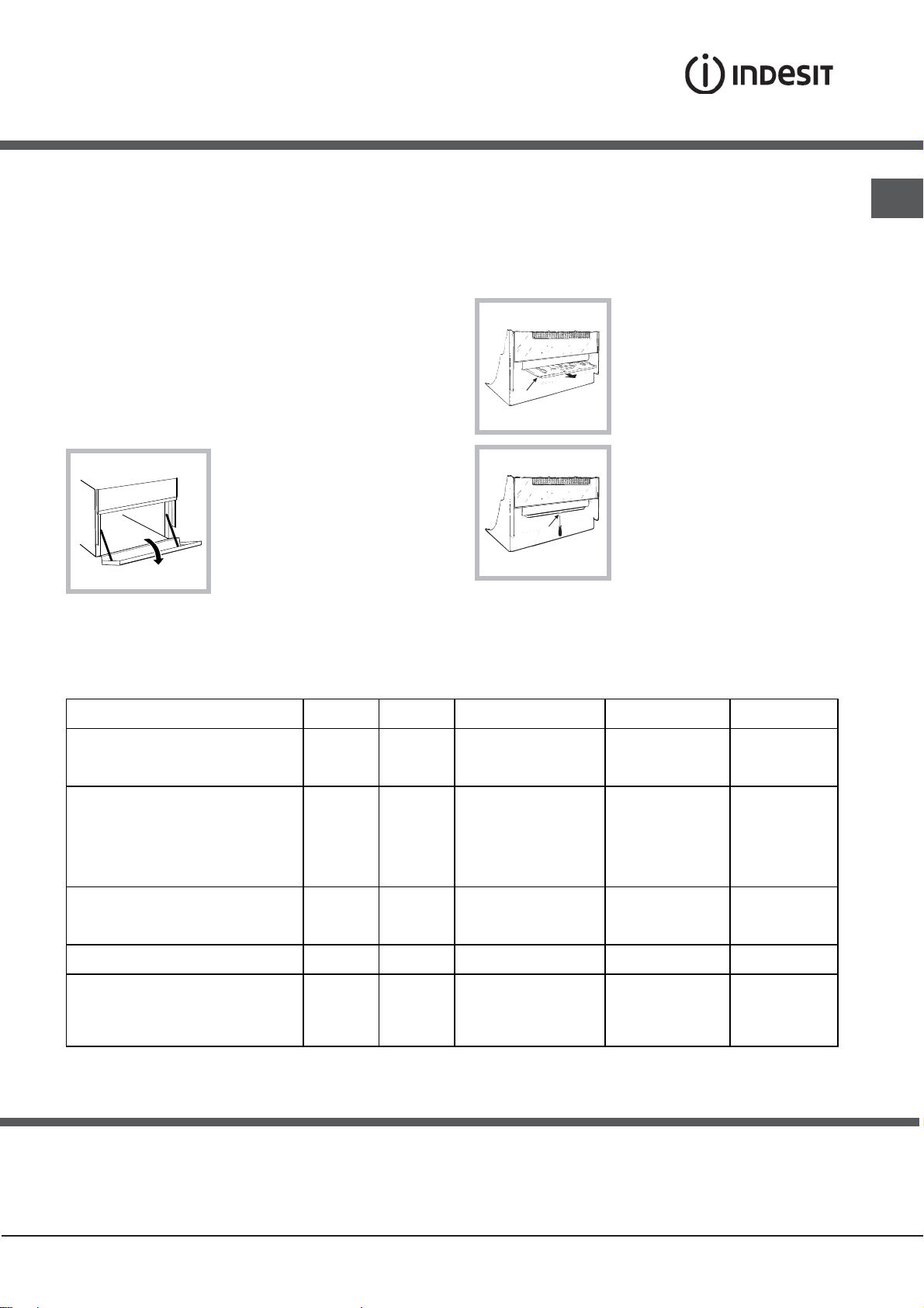
Lower compartment
There is a compartment
underneath the oven that
may be used to store oven
accessories or deep dishes.
To open the door pull it
downwards (see gure).
Oven cooking advice table
Foods
Pasta
Lasagne
Cannelloni
Gratin dishes
Meat
Veal
Chicken
Duck
Rabbit
Pork
Lamb
Fish
Mackerel
Dentex
Trout baked in foil
Pizza
Neapolitan-style
Pies
Biscuits
Tart
Savoury pies
Leavened cakes
Weight (in
kg)
2.5
2.5
2.5
1.5
1.5
1.8
2
2.1
1.8
1.1
1.5
1
1
0.5
1.1
1
1
Rack
position
4
4
4
3
3
3
3
3
3
3
3
3
4
4
4
4
4
In gas cooker models, there is
a sliding protection layer A that
shields the lower compartment
from the heat generated by the
burner (see gure).
To remove the sliding
protection remove the screw S
(see gure). To replace it, lock it
in place with the screw S.
S
! Before using the oven make
sure that the sliding protection
is fixed correctly.
Preheating time (min)
10
10
10
10
10
10
10
10
10
10
10
10
15
15
15
15
15
Recommended
Temperature (°C)
200-210
200
200
200-210
210-220
200
200
200
200
180-200
180-200
180-200
210-220
180
180
180
170
Cooking time
(minutes)
100-110
100-105
75-85
50-60
50-60
95-100
90-100
70-80
70-80
45-50
45-55
45-50
20-25
25-35
40-45
50-55
40-45
Precautions and tips
! This appliance has been designed and manufactured
in compliance with international safety standards.
The following warnings are provided for safety reasons
and must be read carefully.
General safety
• These instructions are only valid for the
countries whose symbols appear in the manual
and on the serial number plate.
9

Precautions and tips
• The appliance was designed for domestic use inside
GB
the home and is not intended for commercial or
• The appliance must not be installed outdoors, even
in covered areas. It is extremely dangerous to leave
the appliance exposed to rain and storms.
• Do not touch the appliance with bare feet or with wet
or damp hands and feet.
• The appliance must be used by adults only for
the preparation of food, in accordance with the
instructions outlined in this booklet. Any other
use of the appliance (e.g. for heating the room)
constitutes improper use and is dangerous.
The manufacturer may not be held liable for any
damage resulting from improper, incorrect and
unreasonable use of the appliance.
• The instruction booklet accompanies a class 1
(insulated) or class 2 - subclass 1 (recessed
between 2 cupboards) appliance.
• Keep children away from the oven.
• Make sure that the power supply cables of other
electrical appliances do not come into contact with
the hot parts of the oven.
• The openings used for the ventilation and dispersion
of heat must never be covered.
• Do not close the glass hob cover (selected models
only) when the burners are alight or when they are
still hot.
• Always use oven gloves when placing cookware in
the oven or when removing it.
• Do not use flammable liquids (alcohol, petrol, etc...)
near the appliance while it is in use.
• Do not place flammable material in the lower storage
compartment or in the oven itself. If the appliance is
switched on accidentally, it could catch fire.
• Always make sure the knobs are in the • position
and that the gas tap is closed when the appliance is
not in use.
• When unplugging the appliance, always pull the
plug from the mains socket; do not pull on the cable.
• Never perform any cleaning or maintenance work
without having disconnected the appliance from the
electricity mains.
• If the appliance breaks down, under no
circumstances should you attempt to repair
the appliance yourself. Repairs carried out by
inexperienced persons may cause injury or further
malfunctioning of the appliance. Contact Assistance.
• Do not rest heavy objects on the open oven door.
• Do not let children play with the appliance.
• The appliance should not be operated by people
(including children) with reduced physical, sensory
or mental capacities, by inexperienced individuals
or by anyone who is not familiar with the product.
These individuals should, at the very least, be
supervised by someone who assumes responsibility
for their safety or receive preliminary instructions
relating to the operation of the appliance.
industrial use.
Disposal
• When disposing of packaging material: observe
local legislation so that the packaging may be
reused.
• The European Directive 2002/96/EC relating
to Waste Electrical and Electronic Equipment
(WEEE) states that household appliances should
not be disposed of using the normal solid urban
waste cycle. Exhausted appliances should be
collected separately in order to optimise the cost
of re-using and recycling the materials inside the
machine, while preventing potential damage to the
atmosphere and to public health. The crossed-out
dustbin is marked on all products to remind the
owner of their obligations regarding separated
waste collection.
Exhausted appliances may be collected by the
public waste collection service, taken to suitable
collection areas in the area or, if permitted by
current national legislation, they may be returned to
the dealers as part of an exchange deal for a new
equivalent product.
All major manufacturers of household appliances
participate in the creation and organisation of
systems for the collection and disposal of old and
disused appliances.
Respecting and conserving the
environment
• Whenever possible, avoid pre-heating the oven
and always try to fill it. Open the oven door as little
as possible because heat is lost every time it is
opened. To save a substantial amount of energy,
simply switch off the oven 5 to 10 minutes before the
end of your planned cooking time and use the heat
the oven continues to generate.
• Automatic programmes are based on standard food
product.
• Keep gaskets clean and tidy to prevent any door
energy losses
• If you have a timed tariff electricity contract, the “delay
cooking” option will make it easier to save money by
moving operation to cheaper time periods.
• The base of your pot or pan should cover the hot plate.
If it is smaller, precious energy will be wasted and
pots that boil over leave encrusted remains that can
be difficult to remove.
• Cook your food in closed pots or pans with well-fitting
lids and use as little water as possible. Cooking with
the lid off will greatly increase energy consumption
• Use purely flat pots and pans
• If you are cooking something that takes a long time,
it's worth using a pressure cooker, which is twice as
fast and saves a third of the energy.
10

Removing and fitting the oven door:
Removing and fitting the oven door:
1.Open the door
2.Make the hinge clamps of the oven door rotate
backwards completely (see photo)
3. Close the door until the clamps stop (the door will
remain open for 40° approx.) (see photo)
404040
°
6.Replace the glass.
WARNING! Oven must not be operated with inner
WARNING! Oven must not be operated with inner
WARNING! Oven must not be operated with inner
door glass removed!
door glass removed!
door glass removed!
WARNING! When reassembling the inner door
WARNING! When reassembling the inner door
WARNING! When reassembling the inner door
glass insert the glass panel correctly so that the
glass insert the glass panel correctly so that the
glass insert the glass panel correctly so that the
inscription written on the panel is not reversed and
inscription written on the panel is not reversed andinscription written on the panel is not reversed and
can be easily legible.
can be easily legible.
can be easily legible.
7.Replace the profile, a click will indicate that the
part is positioned correctly.
8.Open the door completely.
9.Close the supports (see photo).
GB
4.Press the two buttons on the upper profile and
extract the profile (see photo)
5.Remove the glass sheet and do the cleaning as
indicated in chapter: "Care and maintenance".
10.Now the door can be completely closed and the
oven can be started for normal use.
11
Care and maintenance
GB
• Check the door seals regularly and wipe them clean
to ensure they are free of debris so that they adhere
properly to the door, thus avoiding
heat dispersion.
Switching the appliance off
Disconnect your appliance from the electricity supply
before carrying out any work on it.
Cleaning the appliance
! Do not use abrasive or corrosive detergents such as
stain removers, anti-rust products, powder detergents
or sponges with abrasive surfaces: these may scratch
the surface beyond repair.
! Never use steam cleaners or pressure cleaners on
the appliance.
• It is usually sufficient simply to wash the hob using a
damp sponge and dry it with absorbent kitchen roll.
• The stainless steel or enamel-coated external parts
and the rubber seals may be cleaned using a
sponge that has been soaked in lukewarm water
and neutral soap. Use specialised products for the
removal of stubborn stains. After cleaning, rinse well
and dry thoroughly. Do not use abrasive powders or
corrosive substances.
• The hob grids, burner caps, flame spreader rings
and the hob burners can be removed
to make cleaning easier; wash them in hot water and
non-abrasive detergent, making sure all burnt-on
residue is removed before drying them thoroughly.
• For hobs with electronic ignition, the terminal part of
the electronic lighting devices should be cleaned
frequently and the gas outlet holes should be
checked for blockages.
Clean the glass part of the oven door using a
•
sponge and a non-abrasive cleaning product, then
dry thoroughly with a soft cloth. Do not use rough
abrasive material or sharp metal scrapers as these
could scratch the surface and cause the glass to
crack.
• The accessories can be washed like everyday
crockery, and are even dishwasher safe.
• Stainless steel can be marked by hard water that
has been left on the surface for a long time, or by
aggressive detergents containing phosphorus.
After cleaning, rinse well and dry thoroughly. Any
remaining drops of water should also be dried.
Inspecting the oven seals
Check the door seals around the oven periodically. If
the seals are damaged, please contact your nearest
Authorised After-sales Service Centre. We recommend
that the oven is not used until the seals have been
replaced.
Gas tap maintenance
Over time, the taps may become jammed or difficult to
turn. If this occurs, the tap must be replaced.
! This procedure must be performed by a qualified
technician who has been authorised by the
manufacturer.
Assistance
Please have the following information handy:
• The appliance model (Mod.).
• The serial number (S/N).
This information can be found on the data plate located
on the appliance and/or on the packaging.
• The inside of the oven should ideally be cleaned
after each use, while it is still lukewarm. Use hot
water and detergent, then rinse well and dry with a
soft cloth. Do not use abrasive products.
12
Instalacja
! Zachować niniejszą książeczkę instrukcji by móc
ją konsultować w przyszłości w dowolnej chwili. W
przypadku sprzedaży, odstąpienia lub przeniesienia
urządzenia, należy upewnić się, czy instrukcja została
przekazana wraz z nim.
! Należy uważnie przeczytać instrukcję: zawiera ona
ważne informacje dotyczące instalacji, użytkowania i
bezpieczeństwa.
! Instalacja urządzenia powinna zostać wykonana
zgodnie z niniejszymi instrukcjami i przez
wykwalifi kowany personel.
! Wszelkie działania w zakresie regulacji lub
konserwacji muszą być wykonywane przy kuchence
odłączonej od zasilania elektrycznego.
Wentylacja pomieszczeń
Urządzenie może zostać zainstalowane wyłącznie
w pomieszczeniach ze stałą wentylacją, zgodnie z
obowiązującymi normami krajowymi. W pomieszczeniu,
w którym jest instalowane urządzenie, musi by
zapewniony taki dopływ powietrza, jaki jest niezbędny
dla prawidłowego spalania gazu (natężenie przepływu
powietrza nie powinno być niższe od 2 m
zainstalowanej mocy).
Wloty powietrza, zabezpieczone przez kratki, powinny
mieć przewód o przekroju użytkowym co najmniej 100
2
i powinny zostać rozmieszczone tak, aby nie mogły
cm
ulec nawet częściowemu zatkaniu (patrz rysunek A).
Wymiar tych wlotów powinien zostać zwiększony o
100% – do minimum 200 cm
urządzenia nie posiada urządzenia zabezpieczającego
przed brakiem płomienia i kiedy dopływ powietrza
następuje w sposób niebezpośredni z przyległych
pomieszczeń (patrz rysunek B) – o ile nie są one
częściami wspólnymi budynku, pomieszczeniami
zagrożonymi pożarem lub sypialniami – wyposażonych
w przewód wentylacyjny z wyjściem na zewnątrz, jak
opisano powyżej.
2
– jeśli płyta robocza
ć
3
/h na kW
Odprowadzanie spalin
Odprowadzanie spalin musi być zapewnione przez
okap połączony z kominem o ciągu naturalnym i o
sprawnym działaniu lub przez wentylator elektryczny,
który włącza się automatycznie przy każdym
uruchomieniu urządzenia (patrz rysunki).
Odprowadzanie
bezpośrednio na
zewnątrz
! Skroplone gazy pochodne ropy naftowej, cięższe
od powietrza, opadają w dół, dlatego pomieszczenia,
w których znajdują się butle GPL, powinny być
wyposażone w otwory wychodzące na zewnątrz,
umożliwiające odpływ dołem ewentualnych wycieków
gazu.
Butle GPL, niezależnie od tego czy są puste, czy
częściowo napełnione, nie powinny być instalowane
ani składowane w pomieszczeniach lub wnękach
położonych poniżej poziomu podłogi (piwnice, itp.). W
pomieszczeniu należy przechowywać jedynie aktualnie
użytkowaną butlę, z dala od źródeł ciepła (piece,
kominki, piecyki), mogących doprowadzić do wzrostu jej
temperatury powyżej 50°C.
Odprowadzanie przez komin
lub rozgałęziony kanał dymowy
(wyłącznie do urządzeń kuchennych)
Ustawienie i wypoziomowanie
! Możliwe jest zainstalowanie urządzenia obok mebli,
których wysokość nie przekracza poziomu roboczego.
PL
A. B
A
Otwarcie wentylacji dla
powietrza do spalania
! Po dłuższym użytkowaniu urządzenia zaleca się
otwarcie okna lub zwiększenie prędkości ewentualnych
wentylatorów.
Zwiększenie szczeliny
pomiędzy drzwiami a podłogą
! Należy upewnić się, czy ściana stykająca się z tyłem
urządzenia wykonana jest z materiału niepalnego i
odpornego na ciepło (T 90°C).
Dla zapewnienia prawidłowej instalacji:
• ustawić urządzenie w kuchni, w jadalni lub w innym
pomieszczeniu (nie w łazience);
• jeśli płaszczyzna kuchenki jest wyższa w stosunku
do płaszczyzny mebli, powinny one zostać
umieszczone w odległości co najmniej 600 mm od
urządzenia;
• jeśli kuchenka jest instalowana pod szafką wiszącą,
powinna ona znajdować się w odległości minimum
420 mm od płyty kuchenki.
Odległość ta powinna wynosić 700 mm, jeśli szafki
13
PL
HOOD
420
Min.
min.
650
mm. with hood
min.
700
mm. without hood
mm.
600
Min. mm.
420
Min. mm.
wiszące są łatwopalne
(patrz rysunek);
• nie umieszczać
zasłon za kuchenką, ani
w odległości mniejszej
niż 200 mm od jej
krawędzi;
• ewentualne okapy
powinny zostać
zainstalowane według
zaleceń odpowiedniej
instrukcji.
Wypoziomowanie
Jeśli konieczne jest
wypoziomowanie urządzenia,
należy przykręcić nóżki
regulacyjne, dostarczane jako
wyposażenie, w odpowiednich
gniazdach umieszczonych w
rogach podstawy kuchenki
(patrz rysunek).
Nóżki* mocowane są w
otworach pod podstawą
kuchenki.
*Dostępne tylko w niektórych modelach
gniazdko lub wtyczkę; nie stosować przedłużaczy
ani rozgałęźników.
! Po zainstalowaniu urządzenia przewód elektryczny i
gniazdko prądu powinny być łatwo dostępne.
! Kabel nie powinien mieć zgięć, ani nie powinien być
zgnieciony.
! Przewód musi być okresowo sprawdzany i
wymieniany wyłącznie przez autoryzowany personel
techniczny.
! W przypadku nie przestrzegania powyższych
warunków producent zwolniony zostanie z
wszelkiej odpowiedzialności.
Podłączenie gazu
Podłączenie do sieci gazowej lub do butli gazowej
może być wykonane przy pomocy przewodu giętkiego
gumowego lub stalowego, zgodnie z obowiązującymi
normami krajowymi oraz po upewnieniu się czy
urządzenie jest wyregulowane odpowiednio dla
typu gazu, którym będzie zasilane (patrz etykieta
kalibracyjna na pokrywie: w przeciwnym razie patrz
niżej). W przypadku zasilania płynnym gazem
z butli, stosować regulatory ciśnienia zgodne z
obowiązującymi normami krajowymi. Dla ułatwienia
podłączenia zasilanie gazem może być skierowane
bocznie*: zastąpić złączkę przewodu giętkiego
zatyczką i wymienić uszczelkę, dostarczaną jako
wyposażenie.
Podłączenie do sieci elektrycznej
Zamocować na przewodzie znormalizowaną wtyczkę
dostosowaną do obciążeń wskazanych na tabliczce
znamionowej umieszczonej na urządzeniu (patrz tabela
Dane techniczne).
W przypadku bezpośredniego podłączenia do sieci
koniecznym jest zainstalowanie pomiędzy urządzeniem
a siecią wyłącznika polowego z otwarciem minimalnym
pomiędzy stykami 3 mm przeznaczonego do
obciążeń i odpowiadającego obowiązującym normom
(przewód uziemienia nie powinien być przerywany
przez wyłącznik). Przewód zasilania powinien być
umieszczony tak, aby w żadnym punkcie jego
temperatura nie przekraczała temperatury otoczenia o
50°C.
Przed wykonaniem podłączenia należy upewnić się, czy:
• gniazdko posiada odpowiednie uziemienie i jest zgodne
z obowiązującymi przepisami;
• gniazdko jest w stanie wytrzymać maksymalne
obciążenie mocy urządzenia, wskazane na tabliczce
znamionowej;
• napięcie zasilania odpowiada wartościom podanym
na tabliczce znamionowej;
• gniazdko jest kompatybilne z wtyczką urządzenia.
li gniazdko nie jest kompatybilne, wymienić
Jeś
14
! Dla zapewnienia bezpieczeństwa pracy,
odpowiedniego zużycia energii i zwiększenia
trwałości urządzenia, należy się upewnić czy ciśnienie
zasilania mieści si
ę w granicach wskazanych w tabeli
Charakterystyka palników i dysz (patrz niżej).
Podłączenie gazu przy pomocy przewodu
gumowego
Sprawdzić czy przewód odpowiada obowiązującym
normom krajowym. Wewnętrzna średnica przewodu
powinna wynosić: 8 mm przy zasilaniu gazem płynnym;
13 mm przy zasilaniu metanem.
Po wykonaniu podłączenia upewnić się czy przewód:
• nie styka się w żadnym punkcie z częściami, które
osiągają temperatury przekraczające 50°C;
• nie jest narażony na naciągnięcie ani poskręcanie i
nie ma na nim zagięć lub przewężeń;
• nie ma styczności z przedmiotami tnącymi, ostrymi
krawędziami, ruchomymi częściami i nie jest
przygnieciony;
GORĄCA
Punkt przyłączenia
Kurek zamykający
Położenie węża
Punkt przyłączenia
Położenie węża
POWIERZCHNIA
Kurek zamykający
• jest łatwo dostępny na całej długości dla
umożliwienia wykonywania kontroli jego stanu;
• jego długość wynosi mniej niż 1500 mm;
• jest dobrze umocowany na dwóch końcach za
pomocą odpowiednich zacisków mocujących,
zgodnych z obowiązującymi normami krajowymi.
! Jeśli nie może być spełniony jeden z tych warunków
lub ich większa liczba, albo jeśli kuchenka jest
instalowana zgodnie z warunkami klasy 2 - podklasy 1
(urządzenie umiejscowione pomiędzy dwoma meblami),
należy zastosować przewód giętki stalowy (patrz niżej).
Dostosowanie płyty grzejnej
Wymiana dysz palników płyty:
1. zdjąć kratki i wykręcić palniki z
2. odkręcić dysze, posługując się kluczem rurowym
7 mm (patrz rysunek) i wymienić je na te, które są
przystosowane do nowego rodzaju gazu (patrz tabela
Charakterystyka palników i dysz);
3. przywrócić na swoje miejsce wszystkie komponenty
wykonując czynności w kolejności odwrotnej w stosunku
do powyższej sekwencji.
gniazd;
PL
Podłączenie gazu przy pomocy przewodu giętkiego
ze stali nierdzewnej o pełnych ściankach z
gwintowanymi złączami.
Sprawdzić czy przewód i uszczelki odpowiadają
obowiązującym normom krajowym.
Aby zamontować przewód należy usunąć złączkę
przewodu gię
(złącze wejściowe gazu do urządzenia jest gwintowane
gwintem gazowym 1/2 walcowym męskim).
! Wykonać podłączenie tak, aby całkowita długość
przewodów nie przekraczała 2 metrów oraz upewnić się
czy przewód nie styka się z ruchomymi częściami i czy
nie jest przygnieciony.
Kontrola szczelności
Po zakończeniu instalacji sprawdzić szczelność
wszystkich złącz stosując w tym celu roztwór mydlany,
nigdy płomień.
tkiego znajdującą się na urządzeniu
Dostosowanie do różnych rodzajów gazu
Regulacja minimum palników płyty:
1. ustawić kurek w położeniu minimum;
2. zdjąć pokrętło i kręcić śrubą regulacyjną znajdującą
się wewnątrz lub obok osi kurka aż do uzyskania
małego regularnego p
! W przypadku gazów płynnych śruba regulacyjna
powinna być dokręcona do końca;
3. sprawdzić czy podczas szybkiego obracania
pokrętłem z położenia maksymalnego do minimalnego
nie następuje gaśnięcie palników.
! Palniki płyty nie wymagają regulacji powietrza
pierwotnego.
! Po wykonaniu regulacji dla gazu innego niż
oryginalnie przewidziany, należy wymienić poprzednią
etykietę kalibracyjną na etykietę odpowiadającą
nowemu gazowi, dostępną w naszych Autoryzowanych
Centrach Obsługi Technicznej.
! W sytuacji, gdy ciśnienie gazu jest inne (lub zmienne)
od przewidzianego, konieczne jest zainstalowanie na
łomienia.
Urządzenie może być dostosowane do innego rodzaju
gazu niż ten, którym jest aktualnie zasilane (wskazany
na etykiecie kalibracyjnej na
pokrywie).
przewodach doprowadzających regulatora ciśnienia,
zgodnie z obowiązującą normą krajową dotyczącą
„kanałowych regulatorów gazu”.
15
PL
S
S
R
A
S
A
Tabela 1 (dla Polski)
Palnik
Duży (R)
Półszybki (średni) (S)
Pomocniczy (mały) (A)
Piekarnik
Ciśnienia zasilania
Uwaga! Aby zdemontować osłonę dolną “A”, należy
wykręcić wkręt “S”. PO
zakończeniu należy
ponownie włożyć
osłonę i wkręcić wkręt
„S”. Przed użyciem
piekarnika proszę
upewnić się, czy osłona
„A” została poprawnie
zainstalowana
I5GG /U
DANE TECHNICZNE
Wymiary
piekarnika W x D
34x44x39 cm
x G
Objętość
(l) 58
Wymiary
użytkowe
szuflady do
podgrzewania
szerokość (cm) 42
głębokość (cm) 44
wysokość (cm) 17
potraw
mogą być dostosowane do
Palniki
wszystkich rodzajów gazu
wskazanych na tabliczce
znamionowej
Napięcie i
częstotliwość
zasilania
patrz tabliczka znamionowa
elektrycznego
Dyrektywy unijne: 2006/95/EC z
dnia 12/12/06 (niskie napięcie) z
późniejszymi zmianami 2004/108/EC z dnia 15/12/04
(zgodność elektromagnetyczna) z
późniejszymi zmianami 93/68/EEC z dnia 22/07/93 z
późniejszymi zmianami,
90/396/EEC z dnia 29/06/90 (gaz)
z późniejszymi zmianami, 93/68/EEC z dnia 22/07/93 z
późniejszymi zmianami, 2002/96/EC.
ETYKIETA EKTYWNOŚCI ENERGETYCZNEJ i ECODESIGN
Dyrektywa UE nr 65/2014, integrująca
dyrektywę 2010/30/EU. Rozporządzenie
UE nr 66/2014, integrujące dyrektywę
2009/125/KE
Rozporządzenie EN 15181
Tabela charakterystyk palników i dysz
Średnica
(w mm)
100 3,00 128 286 158 397 3,30 87 247
75 1,90 104 181 143 251 2,10 70 160
51
minimalne (mbar)
nominalne (mbar)
maksymalne (mbar)
* A 15°C 1013 mbar – gaz suchy
G20 (GZ50) p.c.i. = 37,78 MJ/m³
G2.350 (GZ35) p.c.i. = 27,20 MJ/m³
G30 (GPB) p.c.i. = 125,81 MJ/m³
16
- 2,85 119 267 171 370 3,15 80 233
Moc cieplna
(p.c.i.*)
kW
1,00
G20 (GZ50) G2.350 (GZ35) G30 (GPB)
Dysza
1/100
(w mm)
76 95 106 132 1,10 52 95
Przepływ*
l/godz
16
20
25
Dysza
1/100
(w mm)
(X)
Przepływ*
l/godz
10
13
16
Moc cieplna
(p.c.i.*)
kW
Dysza
1/100
(w mm)
29
37
44
Przepływ*
g/godz
 Loading...