


I5GG0G.1 /UA
I5GG0 /UA
EnglishEnglish
English
GB
EnglishEnglish
Operating Instructions
COOKER AND OVEN
Contents
Operating Instructions,1
Description of the appliance-Control Panel,2
Description of the appliance-Overall view,2
Installation,3
Start-up and use,7
Precautions and tips,10
Care and maintenance,11
Assistance,11
UA
Інструкціі з експлуатаціі
Інструкціі з експлуатаціі
Інструкціі з експлуатаціі
КУХНЯ
КУХНЯ
КУХНЯ
ЗмістЗміст
Зміст
Інструкціі з експлуатаціі,1
Опис установки-Панель управління,2
Опис установки-Загальнии вигляд,2
Встановлення,13
Включення і використання,17
Запобіжні засоби і поради,20
Догляд i технічне обслуговування,21
Допомога,21
УкраінськаУкраінська
Украінська
1
GB
1.OVEN CONTROL knob
2.Hob BURNER control knob
Description of the appliance
Control panel
2
Опис плити
UA
Опис плити
Панель управління
Панель управління
GR
1.Ручка ДУХОВКА
2.Ручки для керування газовими
пальниками на варильній поверхні
GB
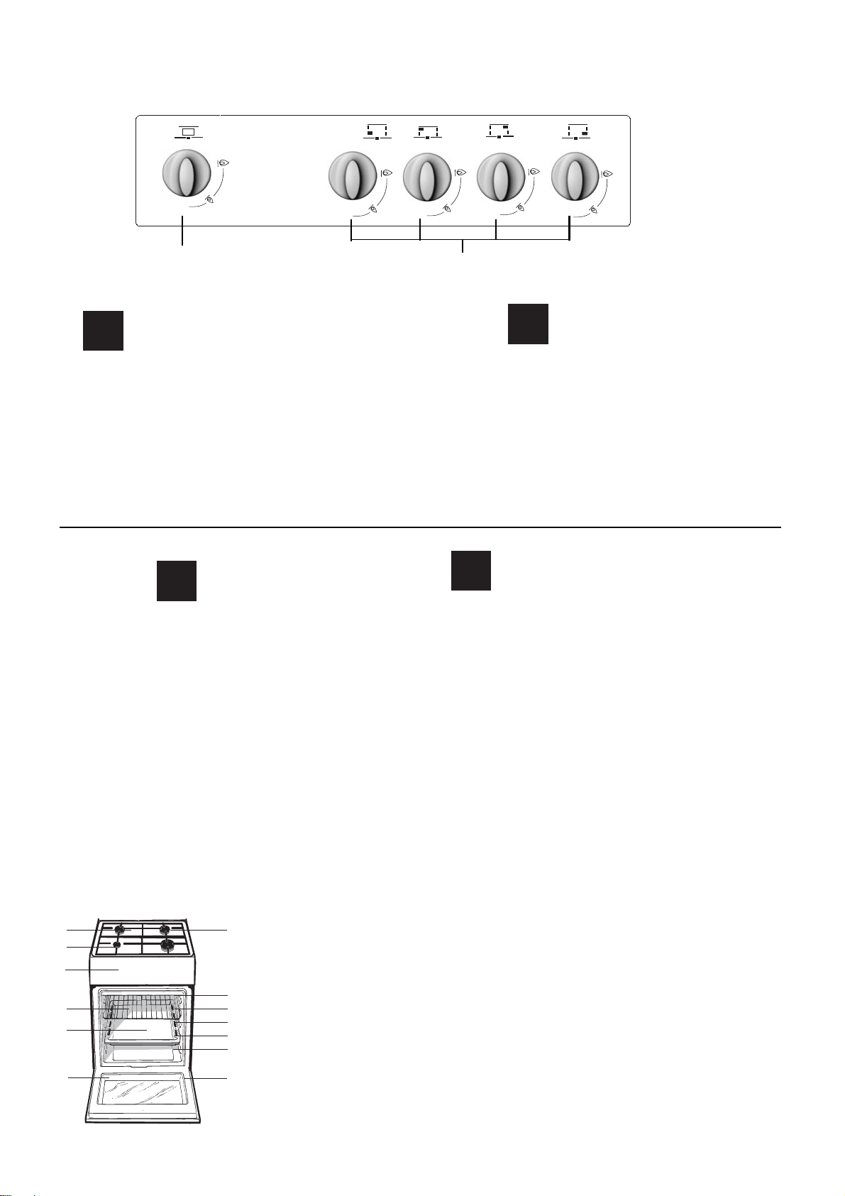
1. Hob burner
2. Hob Grid
3.Containment surface for spills
4.Control panel
5..Sliding grill rack
6.DRIPPING pan
7.Adjustable foot
8.GUIDE RAILS for the sliding racks
9.position 5
10.position 4
11.position 3
12.position 2
13.position 1
1
2
4
5
6
Description
Overall view
3
8
9
10
11
12
13
UA
1.Газовий пальник
2.Піддон на випадок переливань
3.Пoверхня для збирання збiглoї piдини
4.Панель управління
5.Полка РЕШІТKИ
6.Полка ДEКО
7.Лапка для налаштування
8.HAПPABЛЯЮЧІ для полиць
9.положення 5
10.положення 4
11.положення 3
12.положення 2
13.положення 1
Загальнии вигляд
Опис плити
7
2
7
3
GB
! Before operating your new appliance please read
this instruction booklet carefully. It contains important
information concerning the safe installation and
operation of the appliance.
! Please keep these operating instructions for future
reference. Make sure that the instructions are kept with
the appliance if it is sold, given away or moved.
! The appliance must be installed by a qualified
professional according to the instructions provided.
! Any necessary adjustment or maintenance must be
performed after the cooker has been disconnected
from the electricity supply.
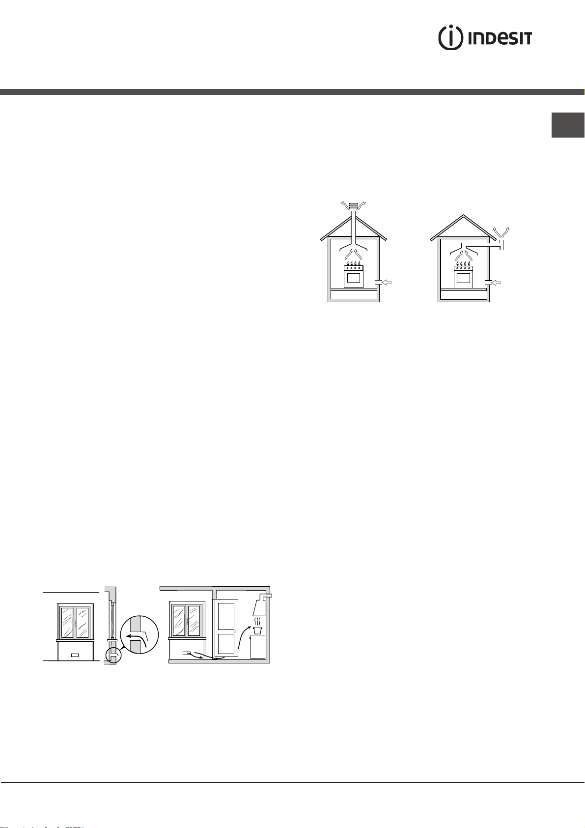
Room ventilation
The appliance may only be installed in permanentlyventilated rooms, according to current national
legislation. The room in which the appliance is installed
must be ventilated adequately so as to provide as
much air as is needed by the normal gas combustion
process (the flow of air must not be lower than 2 m3/h
per kW of installed power).
The air inlets, protected by grilles, should have a duct
with an inner cross section of at least 100 cm2 and
should be positioned so that they are not liable to even
partial obstruction (see gure A).
These inlets should be enlarged by 100% - with a
minimum of 200 cm2 - whenever the surface of the
hob is not equipped with a flame failure safety device.
When the flow of air is provided in an indirect manner
from adjacent rooms (see gure B), provided that these
are not communal parts of a building, areas with
increased fire hazards or bedrooms, the inlets should
be fitted with a ventilation duct leading outside as
described above.
A B
! After prolonged use of the appliance, it is advisable to
open a window or increase the speed of any fans used.
Disposing of combustion fumes
The disposal of combustion fumes should be
guaranteed using a hood connected to a safe and
efficient natural suction chimney, or using an electric
fan that begins to operate automatically every time the
appliance is switched on (see gure).
! The liquefied petroleum gases are heavier than air
and collect by the floor, therefore all rooms containing
LPG cylinders must have openings leading outside so
that any leaked gas can escape easily.
LPG cylinders, therefore, whether partially or
completely full, must not be installed or stored in rooms
or storage areas that are below ground level (cellars,
etc.). Only the
cylinder being used should be stored in the room; this
should also be kept well away from sources
of heat (ovens, chimneys, stoves) that may cause
the temperature of the cylinder to rise above 50°C.
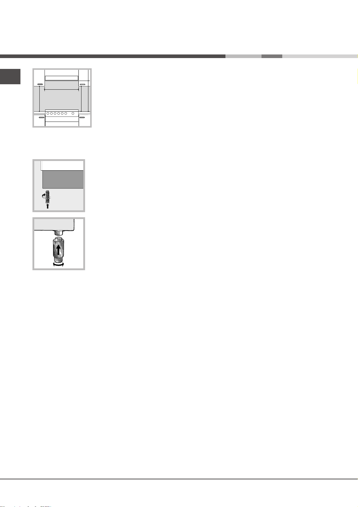
Positioning and levelling
! It is possible to install the appliance alongside
cupboards whose height does not exceed that of the
hob surface.
! Make sure that the wall in contact with the back of
the appliance is made from a non-flammable, heatresistant material (T 90°C).
To install the appliance correctly:
• Place it in the kitchen, dining room or the bed-sit (not
in the bathroom).
• If the top of the hob is higher than the cupboards,
the appliance must be installed at least 200 mm away
from them.
• If the cooker is installed underneath a wall cabinet,
there must be a minimum distance of 420 mm
between this cabinet and the top of the hob.
This distance should be increased to 700 mm if the
wall cabinets are flammable (see gure).
• Do not position blinds behind the cooker or less than
A
Fumes channelled through
a chimney or branched
flue system reserved for
cooking appliances)
Installation
Adjacent room Room requiring
ventilation
Ventilation opening for
comburent air
Increase in the gap between
the door and the flooring
Fumes channelled
straight outside
4
GB
200 mm away from its sides.
• Any hoods must
be installed according to
the instructions listed in the
relevant operating manual.
Levelling
If it is necessary to level the appliance, screw the
adjustable feet into the places provided on each corner
of the base of the cooker (see
gure).
The legs* fit into the slots on the
underside of the base of the
cooker.
Electrical connection
Install a standardised plug corresponding to the load
indicated on the appliance data plate (see Technical
data table).
The appliance must be directly connected to the mains
using an omnipolar circuit-breaker with a minimum contact
opening of 3 mm installed between the appliance and the
mains. The circuit-breaker must be suitable for the charge
indicated and must comply with NFC 15-100 regulations
(the earthing wire must not be interrupted by the circuitbreaker). The supply cable must be positioned so that it
does not come into contact with temperatures higher than
50°C at any point.
Before connecting the appliance to the power supply,
make sure that:
• The appliance is earthed and the plug is compliant with
the law.
• The socket can withstand the maximum power of the
appliance, which is indicated by the data plate.
• The voltage is in the range between the values
indicated on the data plate.
• The socket is compatible with the plug of the
appliance. If the socket is incompatible with the
HOOD
420
Min.
min. 650 mm. with hood
min. 700 mm. without hood
mm.
600
Min. mm.
420
Min. mm.
* Only available in certain models
plug, ask an authorised technician to replace it. Do
not use extension cords or multiple sockets.
! Once the appliance has been installed, the power
supply cable and the electrical socket must be easily
accessible.
! The cable must not be bent or compressed.
! The cable must be checked regularly and replaced
by authorised technicians only.
! The manufacturer declines any liability should
these safety measures not be observed.
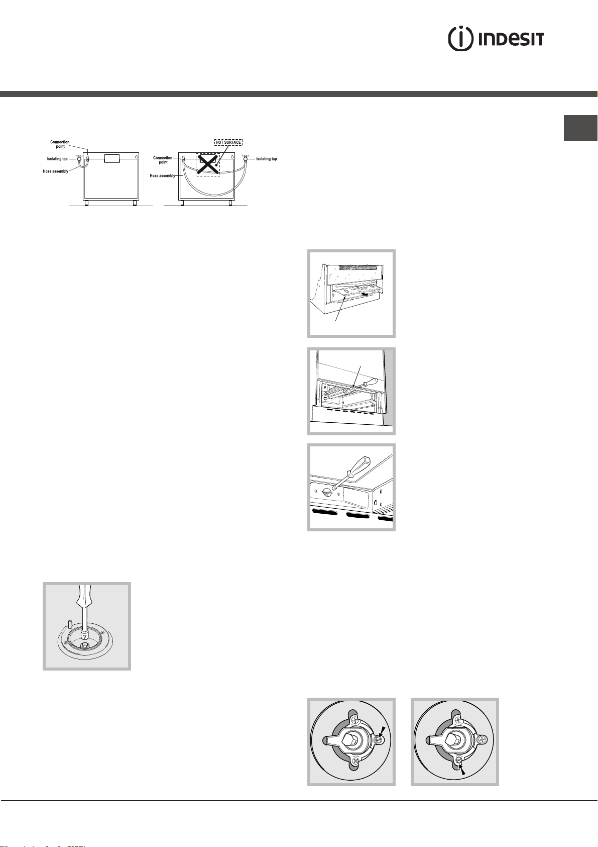
Gas connection
Connection to the gas network or to the gas cylinder
may be carried out using a flexible rubber or steel hose,
in accordance with current national legislation and after
making sure that the appliance is suited to the type of gas
with which it will be supplied (see the rating sticker on
the cover: if this is not the case see below). When using
liquid gas from a cylinder, install a pressure regulator
which complies with current national regulations. To
make connection easier, the gas supply may be turned
sideways*: reverse the position of the hose holder with
that of the cap and replace the gasket that is supplied
with the appliance.
! Check that the pressure of the gas supply is
consistent with the values indicated in the Table
of burner and nozzle specifications (see below).
This will ensure the safe operation and durability of
your appliance while maintaining efficient energy
consumption.
Gas connection using a flexible rubber hose
Make sure that the hose complies with current national
legislation. The internal diameter of the hose must
measure: 8 mm for liquid gas supply; 13 mm for
methane gas supply.
Once the connection has been performed, make sure
that the hose:
• Does not come into contact with any parts that reach
temperatures of over 50°C.
• Is not subject to any pulling or twisting forces and
that it is not kinked or bent.
• Does not come into contact with blades, sharp
corners or moving parts and that it is not
compressed.
• Is easy to inspect along its whole length so that its
condition may be checked.
• Is shorter than 1500 mm.
• Fits firmly into place at both ends, where it will
be fixed using clamps that comply with current
regulations.
the regulatory screw must be fastened as tightly as
possible.
3. While the burner is alight, quickly change the position of
the knob from minimum to maximum and vice versa several
times, checking that the flame is not extinguished.
! The hob burners do not require primary air
adjustment.
GB
! If one or more of these conditions is not fulfilled
or if the cooker must be installed according to the
conditions listed for class 2 - subclass 1 appliances
(installed between two cupboards), the flexible steel
hose must be used instead (see below).
Connecting a flexible jointless stainless steel pipe to
a threaded attachment
Make sure that the hose and gaskets comply with
current national legislation.
To begin using the hose, remove the hose holder on the
appliance (the gas supply inlet on the appliance is a
cylindrical threaded 1/2 gas male attachment).
! Perform the connection in such a way that the hose
length does not exceed a maximum of 2 metres,
making sure that the hose is not compressed and does
not come into contact with moving parts.
Checking the connection for leaks
When the installation process is complete, check the
hose fittings for leaks using a soapy solution. Never
use a flame.
Adapting to different types of gas
It is possible to adapt the appliance to a type of gas
other than the default type (this is indicated on the
rating label on the cover).
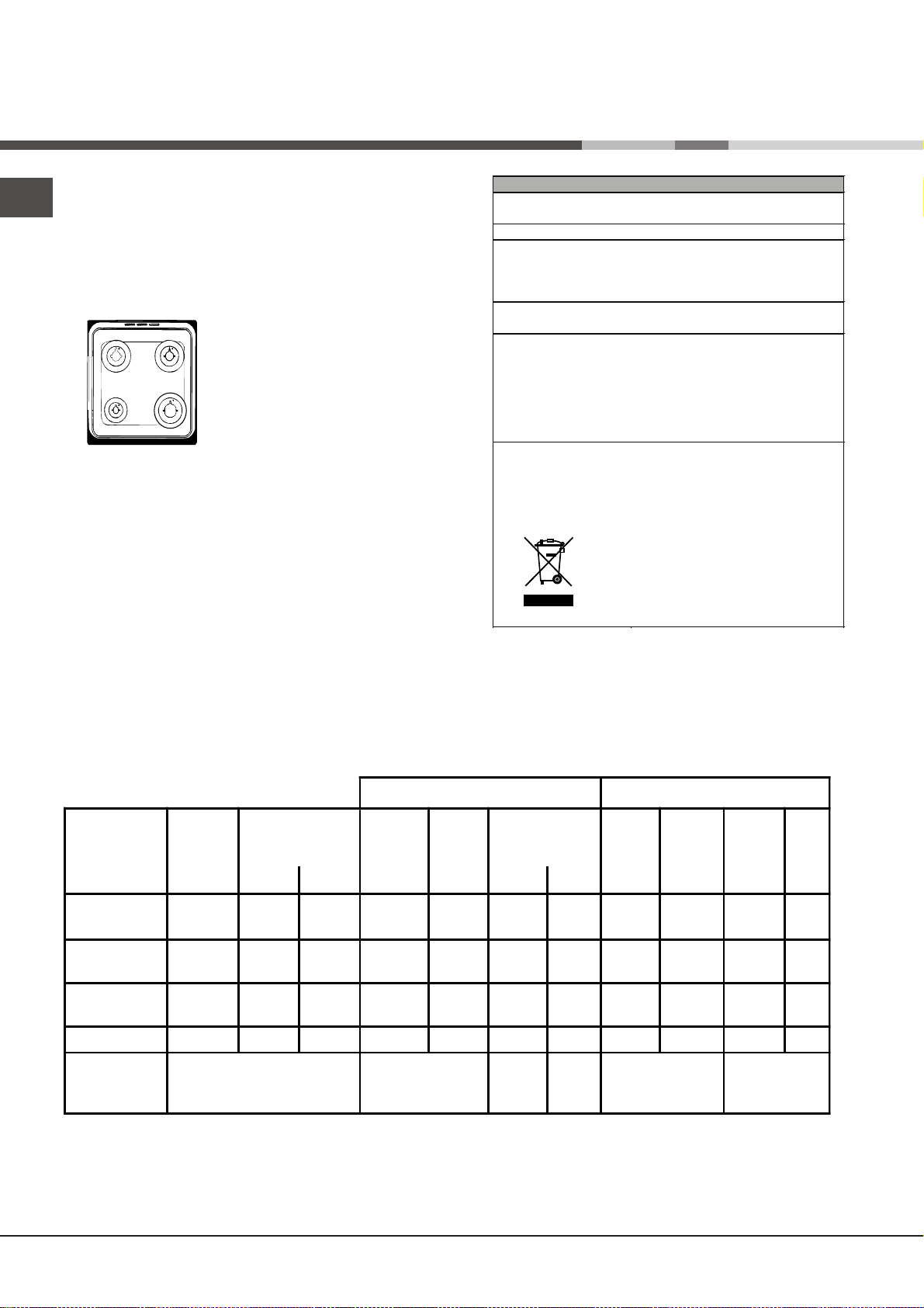
Adapting the oven
Replacing the oven burner
nozzle:
1. Remove the oven
compartment.
2. Slide out the protection panel
A
A
V
(see diagram).
3. Remove the oven burner
after unscrewing the screws V
(see gure).
The whole operation will be
made easier if the oven door is
removed.
4. Unscrew the nozzle using a
special nozzle socket spanner
(see gure) or with a 7 mm
socket spanner, and replace it
with a new nozzle that is suited to the new type of gas
(see Burner and nozzle speci cations table).
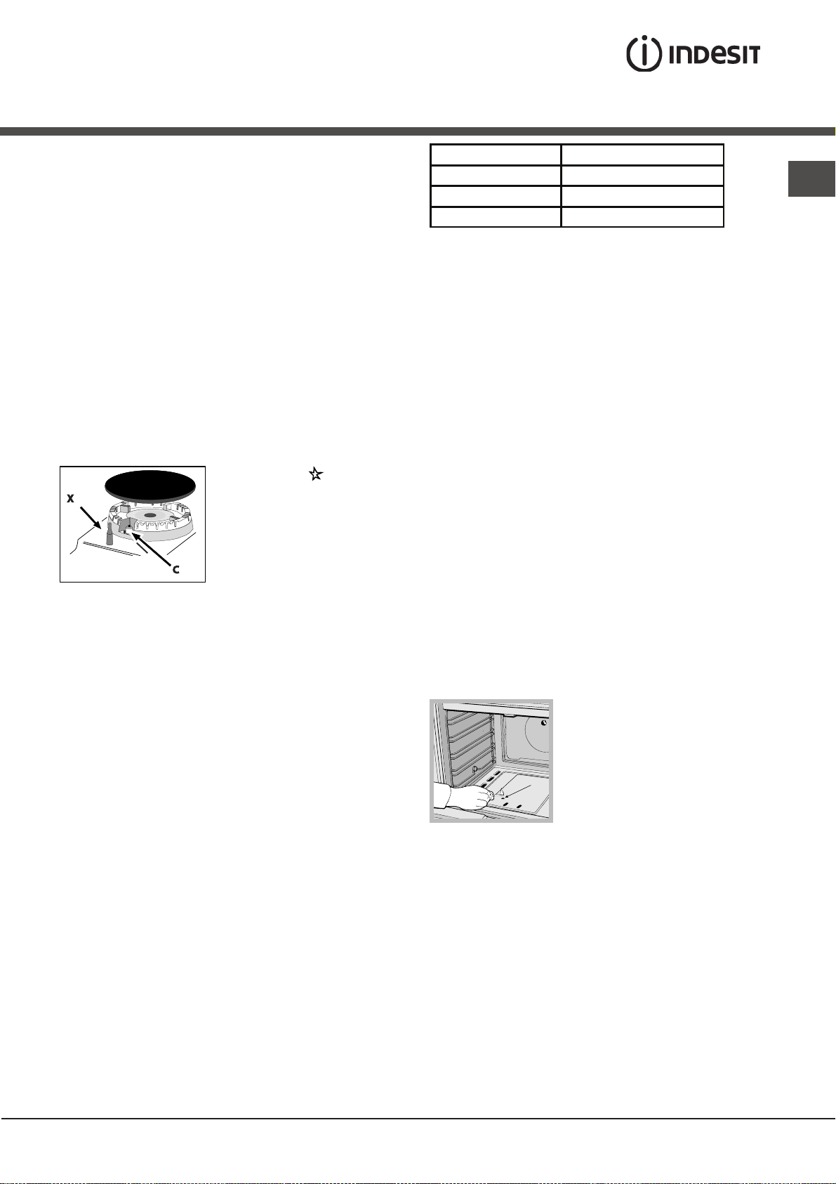
Adapting the hob
Replacing the nozzles for the
hob burners:
1. Remove the hob grids and
slide the burners off their seats.
2. Unscrew the nozzles using
a 7 mm socket spanner (see
gure), and replace them with
nozzles suited to the new type
of gas(see Burner and nozzle speci cations table).
3. Replace all the components by following the above
instructions in reverse.
Adjusting the hob burners’ minimum setting:
1. Turn the tap to the minimum position.
2. Remove the knob and adjust the regulatory screw,
which is positioned inside or next to the tap pin, until
the flame is small but steady.
! If the appliance is connected to a liquid gas supply,
Adjusting the gas oven burner’s minimum setting:
1. Light the burner (see Start-up and Use).
2. Turn the knob to the minimum position (MIN)
after it has been in the maximum position (MAX) for
approximately 10 minutes.
3. Remove the knob.
4. Tighten or loosen the adjustment screws on the
outside of the thermostat pin (see gure) until the flame
is small but steady.
! If the appliance is connected to liquid gas, the
5
GB
adjustment screw must be fastened as tightly as
possible.
5. Turn the knob from the MAX position to the MIN
position quickly or open and shut the oven door,
making sure that the burner is not extinguished.
S
S
R
A
I5GG0G.1 /UA
I5GG0 /UA
TECHNICAL DATA
Oven dimensions
(HxWxD)
Volume
Useful
measurements
relating to the oven
compartment
Power supply voltage
and frequency
Burners
34x39x38 cm
58 l
width 42 cm
depth 44 cm
height 17 cm
see data plate
may be adapted for use with any
type of gas shown on the data
plate, which is located inside the
flap or, after the oven
compartment has been opened,
on the left-hand wall inside the
oven.
EC Directives: 2006/95/EC dated
12/12/06 (Low Voltage) and
subsequent amendments 2004/108/EC dated 15/12/04
(Electromagnetic Compatibility)
and subsequent amendments 2009/142/EC dated 30/11/09
(Gas) and subsequent
amendments - 93/68/EEC dated
22/07/93 and subsequent
amendments - 2002/96/EC.
1275/2008 (Stand-by/ Off mode)
Table of burner and nozzle specifications
Table 1 Liquid Gas Natural Gas
#
'$%
;#
<&;
@D
;@
( ) + 2) 62 6+ 62 62: +( 62:
)> ? + ( ) (2 (: + 2 2 2
> + ( >6 )( ) ): ?> 2 ?>
EF 6 +2+? :2 +> +( ) ? + ?
;
* At 15°C and 1013 mbar- dry gas
** Propane P.C.S. = 50,37 MJ/Kg
*** Butane P.C.S. = 49,47 MJ/Kg
Natural P.C.S. = 37,78 MJ/m
!""
#
$
!""
#
! %&&
!G
<G
<DG
3
62(
6
(>
()
6>
+>
6
)
6>
!""
#
(
:H>
2
6
7
GB
Using the hob
Lighting the burners
For each BURNER knob there is a complete ring showing
the strength of the flame for the relevant burner.
To light one of the burners on the hob:
1. Bring a flame or gas lighter close to the burner.
2. Press the BURNER knob and turn it in an
anticlockwise direction so that it is pointing to the
maximum flame setting E.
3. Adjust the intensity of the flame to the desired level
by turning the BURNER knob in an anticlockwise
direction. This may be the minimum setting C, the
maximum setting E or any position in between the two.
If the appliance is fitted with an electronic lighting
device* (see gure), press the ignition button, marked
with the symbol
, then
hold the BURNER knob down
and turn it in an anticlockwise
direction, towards the
maximum flame setting, until
the burner is lit.
Several models are equipped
with an ignition device
which is built into the knob; in this case the electronic
ignition device* is present (C) but the ignition button
is not. Simply press the BURNER knob and turn it
in an anticlockwise direction so that it is pointing
to the maximum flame setting, until the burner is lit.
The burner may be extinguished when the knob is
released. If this occurs, repeat the operation, holding
the knob down for a longer period of time.
! If the flame is accidentally extinguished, switch off the
burner and wait for at least 1 minute before attempting
to relight it.
If the appliance is equipped with a flame failure safety
device*(X), press and hold the BURNER knob for
approximately 2-3 seconds to keep the flame alight
and to activate the device.
To switch the burner off, turn the knob until it reaches
the stop position •.
Practical advice on using the burners
For the burners to work in the most efficient way
possible and to save on the amount of gas consumed,
it is recommended that only pans that have a lid and
a flat base are used. They should also be suited to the
size of the burner.
Start-up and use
To identify the type of burner, please refer to the
diagrams contained in the “Burner and nozzle
specifications”.
Using the oven
! The first time you use your appliance, heat the empty
oven with its door closed at its maximum temperature
for at least half an hour. Ensure that the room is well
ventilated before switching the oven off and opening
the oven door. The appliance may emit a slightly
unpleasant odour caused by protective substances
used during the manufacturing process burning away.
! Before operating the product, remove all plastic film
from the sides of the appliance.
! Never put objects directly on the bottom of the oven;
this will avoid the enamel coating being damaged.
Only use position 1 in the oven when cooking with the
rotisserie spit.
Lighting the oven
To light the oven burner, apply a lighted match or a
lighter to hole and while pressing in all the way set the
oven knob on maximum E.
The burner can be used at
maximum or intermediate
settings. These settings,
maximum E. and minimum C
are indicated on the knob, plus
off, identified by the symbol •
and operative when this symbol
points to the notch.
For the minimum to maximum settings turn the knob
counter clockwise from “Off”.
To turn off the burner, turn the knob clockwise until it
stops (corresponding again with setting •).
! The oven is fitted with a safety device and it is
therefore necessary to hold the OVEN control knob
down for approximately 6 seconds*.
! If the flame is accidentally extinguished, switch off the
burner and wait for at least 1 minute before attempting
to relight the oven.
F
* Only available in certain models.
Burner ř Cookware diameter (cm)
Fast (R) 24 - 26
Semi Fast (S) 16 - 20
Auxiliary (A) 10 - 14
GB
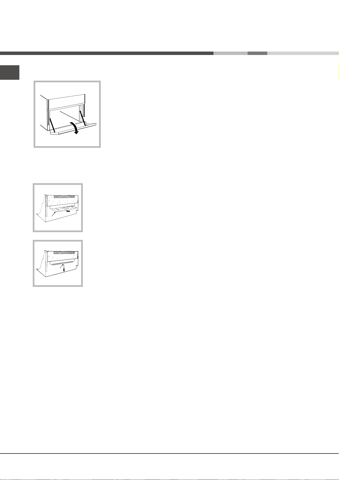
Lower compartment
There is a compartment
underneath the oven
that may be used to
store oven accessories
or deep dishes. To
open the door pull it
downwards (see gure).
! The internal surfaces of the compartment (where
present) may become hot.
! Do not place flammable materials in the lower oven
compartment.
In gas cooker models, there is
a sliding protection layer A that
shields the lower compartment
from the heat generated by the
A
burner (see gure).
To remove the sliding
protection remove the screw S
(see gure). To replace it, lock it
in place with the screw S.
S
! Before using the oven make
sure that the sliding protection
is fixed correctly.
8