

Page 1

Model: H 391F
Page 2
199
650
O 150
max 90 cm
20
A
1
167.2
400
63
A
1
A
2
AB
Fig.1
Fig.2
Fig.1C
A
B
Fig.3
4
Fig.4
Page 3
A
Fig.5
A
B
C
D
E
A
B
C
2
B
Fig.6
C
D
E
A
Fig.7
Fig.9
Fig.8
5
Page 4

6
Page 5

User instructions
GB
English, 7
H 391F
Summary
Installation 4 - 5
General 8
Safety precaution 8
Installation instructions 8
Electric Connection
Fixing to the wall
Fixing the decorative telescopic fl ue
Filtering version
Use and maintenance 9
Replacing halogen light bulbs
Commands
GB
Page 6
General
GB
General
Carefully read the following important information
regarding installation safety and maintenance. Keep this
information booklet accessible for further consultations.
The appliance has been designed for use in the ducting
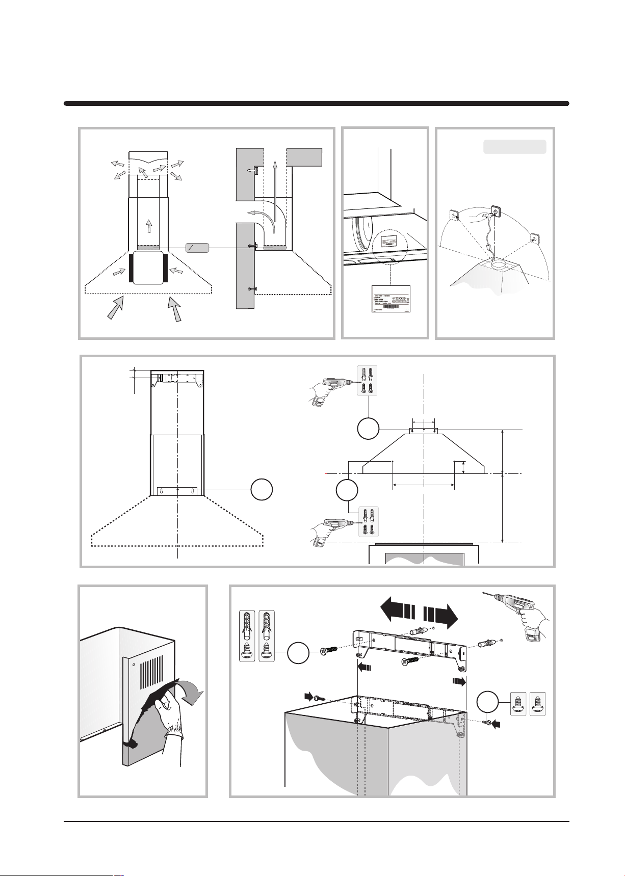
version (air exhaust to the outside – Fig.1B), fi ltering
version (air circulation on the inside – Fig.1A).
Safety precaution
1. Take care when the cooker hood is operating
simultaneously with an open fi replace or burner that
depend on the air in the environment and are supplied
by other than electrical energy, as the cooker hood
removes the air from the environment which a burner
or fi replace need for combustion. The negative pressure
in the environment must not exceed 4Pa (4x10⁻⁵ bar).
Provide adequate ventilation in the environment for a
safe operation of the cooker hood. Follow the local laws
applicable for external air evacuation.
Before connecting the model to the electricity network:
- control the data plate (positioned inside the appliance)
to ascertain that the voltage and power correspond to
the network and the socket is suitable. If in doubt ask a
qualifi ed electrician fi gure 1C.
- If the power supply cable is damaged, it must be replaced
with another cable or a special assembly, which may
be obtained direct from the manufacturer or from the
Technical Assistance Centre.
- This device must be connected to the supply network
through either a plug fused 3A or hardwired to a 2 fase
spur protected by 3A fuse.
2. Warning!
In certain circumstances electrical appliances may
be a danger hazard.
A) Do not check the status of the fi lters while the
cooker hood is operating
B) Do not touch bulbs or adjacent areas, during
or straight after prolonged use of the lighting
installation.
C) Flambè cooking is prohibited underneath the
cooker hood
D) Avoid free fl ame, as it is damaging for the fi lters
and a fi re hazard
E) Constantly check food frying to avoid that the overheated oil may become a fi re hazard
F) Disconnect the electrical plug prior to any maintenance.
G) This appliance is not intended for use by young
children or infi rm persons without supervision
H) Young children should be supervised to ensure
they do not play with the appliance
I) There shall be adequate ventilation of the room
when the rangehood is used at the same time as appliances burning gas or other fuels
L) There is a risk of fi re if cleaning is not carried out
in accordance with the instructions
This appliance conforms to the European Directive
EC/2002/96, Waste Electrical and Electronic Equipment
(WEEE). By making sure that this appliance is disposed
of in a suitable manner, the user is helping to prevent
potential damage to the environment or to public health.
The
symbol on the product or on the accompanying
paperwork indicates that the appliance should not be
treated as domestic waste, but should be delivered to
a suitable electric and electronic appliance recycling
collection point. Follow local guidelines when disposing
of waste. For more information on the treatment, re-use
and recycling of this product, please contact your local
authority, domestic waste collection service or the shop
where the appliance was purchased.
Installation instructions
Assembly and electrical connections must be carried out
by specialised personnel.
• Electric Connection
The appliance has been manufactured as a class II,
therefore no earth cable is necessary.
The connection to the mains is carried out as follows:
BROWN = L line
BLUE = N neutral
If not provided, connect a plug for the electrical load
indicated on the description label. Where a plug is
provided, the cooker hood must be installed in order that
the plug is easily accessible. An omnipolar switch with a
minimum opening of 3mm between contacts, in line with
the electrical load and local standards, must be placed
between the appliance and the network in the case of
direct connection to the electrical network.
• The minimum distance between the support surfaces of
the cooking pots on the cooker top and the lowest part of
the cooker hood must be at least 65 cm. If a connection
tube composed of two parts is used, the upper part
must be placed outside the lower part. Do not connect
the cooker hood exhaust to the same conductor used
to circulate hot air or for evacuating fumes from other
appliances generated by other than an electrical source.
Before proceeding with the assembly operations, remove
the anti-grease fi lter(s) (Fig.7) so that the unit is easier
to handle.
In the case of assembly of the appliance in the suction
8
Page 7

Use and maintenance
version prepare the hole for evacuation of the air.
• We recommend the use of an air exhaust tube which
has the same diameter as the air exhaust outlet hole. If a
pipe with a smaller diameter is used, the effi ciency of the
product may be reduced and its operation may become
noisier.
• Fixing to the wall
Drill the holes A1 respecting the distances indicated
(Fig.2). Fix the appliance to the wall and align it in
horizontal position to the wall units.
When the appliance has been adjusted, defi nitely fi x the
hood using the screws A2 (Fig.5).
For the various installations use screws and screw
anchors suited to the type of wall (e.g. reinforced concrete,
plasterboard, etc.). If the screws and screw anchors are
provided with the product, check that they are suitable for
the type of wall on which the hood is to be fi xed.
• Fixing the decorative telescopic fl ue
Take care not to scratch the duct; wear gloves when
removing the protective fi lm. (Fig. 3).
Arrange the electrical power supply within the dimensions
of the decorative fl ue. If your appliance is to be installed in
the ducting version or in the version with external motor,
prepare the air exhaust opening.
Adjust the width of the support bracket of the upper fl ue
(Fig.4). Then fi x it to the ceiling using the screws A (Fig.4)
in such a way that it is in line with your hood and respecting
the distance from the ceiling indicated in Fig.2.
Connect the fl ange C to the air exhaust hole using a
connection pipe (Fig.5).
Insert the upper fl ue into the lower fl ue and rest above
the frame. Extract the upper fl ue up to the bracket and fi x
it with the screws B (Fig.4).
To transform the hood from a ducting version into a fi ltering
version, ask your dealer for the charcoal fi lters and follow
the installation instructions.
• Filtering version
Install the hood and the two fl ues as described in the
paragraph for installation of the hood in ducting version.
To assemble the fi ltering fl ue refer to the instructions
contained in the kit. If the kit is not provided, order it from
your dealer as accessory.
The fi lters must be applied to the suction unit positioned
inside the hood. They must be centred by turning them 90
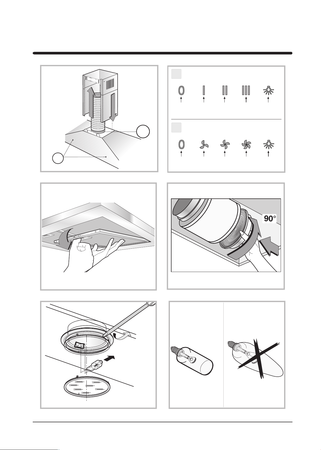
degrees until the stop catch is tripped (fi g. 8).
Use and maintenance
cooked, in order to thoroughly eliminate all contaminated
air.
The effective performance of the cooker hood depends on
constant maintenance; the anti-grease fi lter and the active
carbon fi lter both require special attention.
• The anti-grease fi lter is used to trap any grease particles
suspended in the air, therefore is subject to saturation (the
time it takes for the fi lter to become saturated depends on
the way in which the appliance is used).
- To prevent potential fi re hazards, the anti-grease fi lters
should be washed a minimum of every 2 months (it is
possible to use the dishwasher for this task).
- After a few washes, the colour of the fi lters may change.
This does not mean they have to be replaced.
If the replacement and washing instructions are not
followed, the anti-grease filters may present a fire
hazard.
• The active carbon fi lters are used to purify the air which
is released back into the room.
The fi lters are not washable or re-usable and must be
replaced at least once every four months.
The active carbon fi lter saturation level depends on the
frequency with which the appliance is used, the type of
cooking performed and the regularity with which the antigrease fi lters are cleaned.
• Clean the cooker hood frequently, both inside and outside,
using a cloth which has been dampened with denatured
alcohol or neutral, non-abrasive liquid detergents.
• The light on the cooker hood is designed for use during
cooking and not for general room illumination. Extended
use of the light reduces the average duration of the
bulb.
• Replacing halogen light bulbs (Fig. 9).
To replace the halogen light bulbs B, remove the glass
pane C using a lever action on the relevant cracks.
Replace the bulbs with new ones of the same type.
Caution: do not touch the light bulb with bare hands.
•Commands: (Fig.6 A-B) mechanical the key symbols
are explained below:
A = LIGHT
B = OFF
C = SPEED I
D = SPEED II
E = SPEED III
THE MANUFACTURER DECLINES ALL
RESPONSIBILITY FOR EVENTUAL DAMAGES
CAUSED BY BREACHING THE ABOVE WARNINGS.
GB
• We recommend that the cooker hood is switched on
before any food is cooked. We also recommend that the
appliance is left running for 15 minutes after the food is
9
 Loading...