

Indesit FIM21K-BBKGB User Manual
Operating Instructions
OVEN
GB
English, 1
FIM 21 K.B IX GB
FIM 21 K.B GB
Contents
GB
Installation, 2
Positioning
Electrical connections, 3
Data plate
Description of the appliance, 4
Overall view
Control panel
Start-up and use, 5
Starting the oven
Cooking modes, 6-7
Cooking modes
Practical cooking advice
Cooking advice table
Precautions and tips, 8
General safety
Disposal
Respecting and conserving the environment
Maintenance and care, 9
Switching the appliance off
Cleaning the appliance
Cleaning the oven door
Replacing the light bulb
Guarantee, 10
Assistance, 11
08448 24 24 24
Please phone us on
guarantee
to activate your
Installation
560 mm.
45 mm.
GB
! Before placing your new appliance into operation
please read these operating instructions carefully.
They contain important information for safe use, for
installation and for care of the appliance.
! Please keep these operating instructions for future
reference. Pass them on to possible new owners of
the appliance.
Positioning
! Keep packaging material out of the reach of
children. It can become a choking or suffocation
hazard. (
see Precautions and tips
! The appliance must be installed by a qualified
person in compliance with the instructions provided.
Incorrect installation may cause harm to persons,
animals or may damage property.
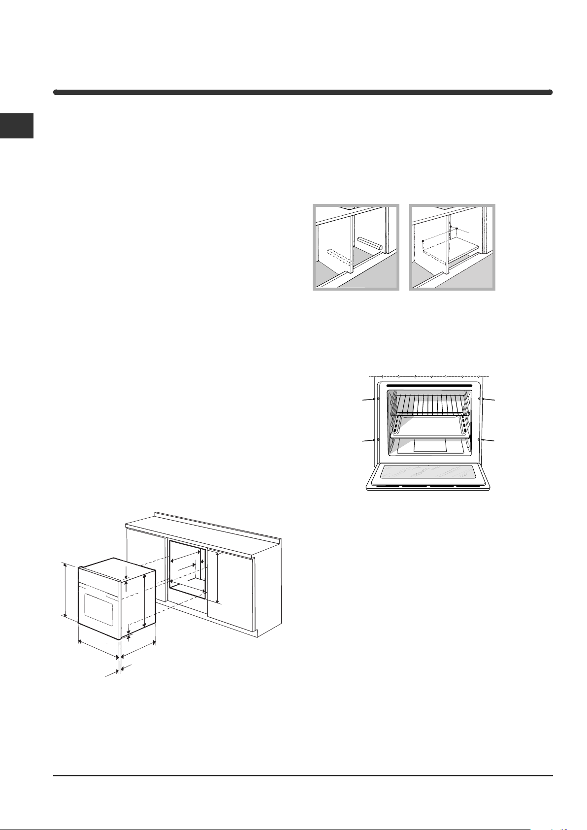
Fitting the appliance
Use the appropriate cabinet to ensure that the
appliance functions properly.
• The panels adjacent to the oven must be made of
heat-resistant material.
).
Ventilation
To ensure good ventilation, the back panel of the
cabinet must be removed. It is advisable to install the
oven so that it rests on two strips of wood, or on a
completely flat surface with an opening of at least 45 x
560 mm (
see diagrams
).
Centring and fastening
Secure the appliance to the cabinet by opening the
oven door and putting 4 screws into the 4 holes of the
outer frame.
• Cabinets with a veneer exterior must be assembled
with glues which can withstand temperatures of up
to 100°C.
• to install the oven under the counter (
see diagram
and in a kitchen unit, the cabinet must have the
following dimensions:
547 mm. min.
23 mm.
595 mm.
5 mm.
595 mm.
545 mm.
24 mm.
45 mm.
560 mm.
575-585 mm.
567 mm.
! The appliance must not come into contact with
electrical parts once it has been installed.
The consumption indications on the data plate have
been calculated for this type of installation.
)
! All parts which ensure the safe operation of the
appliance must not be removable without the aid of a
tool.
PLEASE PHONE US TO REGISTER YOUR APPLIANCE AND ACTIVATE YOUR PARTS GUARANTEE ON 08448 24 24 24
2
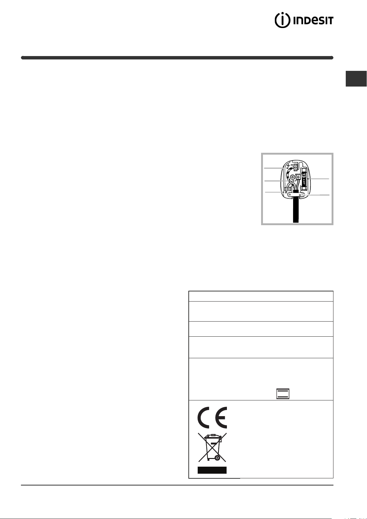
Electrical connection
GREEN &
YELLOW
BROWN
BLUE
13 amp fuse
CROSS-BAR
CORD GRIP
! Ovens with a three-pole power supply cable are
designed to operate with alternated current at the
supply frequency and voltage indicated on the data
plate (at the bottom of the oven dashboard). The
earthing conductor of the cable is the yellow-green
conductor.
Two types of connection are provided:Two types of connection are provided:
Two types of connection are provided:
Two types of connection are provided:Two types of connection are provided:
Connection n° 1
Connecting the power supply cable to the mains.
Fit a normalized plug to the cable, which corresponds
to the load indicated on the data plate; if the cooker is
connected directly to the mains, an omnipolar circuitbreaker with a minimum opening of 3 mm between the
contacts, suitable for the load indicated and
complying with current directives, must be installed
between the appliance and the mains (the earthing
wire must not be interrupted by the circuit-breaker).
The power supply cable must be positioned so that it
does not exceed room temperature by 50°C at any
point of its length. Before making the connection
check that:
• the circuit breakers or fuses of the home system
can support appliance load (see data plate);
• the power supply system has an efficient earthing
connection which complies with the provisions of
current regulations and the law;
• there is easy access to the socket or the omnipolar
circuit-breaker once the cooker has been installed.
! do not use reducers, adapters or shunts as these
could cause heating or burning.
coloured Red. Connect Blue wire to terminal marked
NN
“
N” or coloured Black. If a 13 amp plug (BS 1363) is
NN
used it must be fitted with a 13 amp fuse.
A 15 amp plug must be protected by a 15 amp fuse,
either in the plug or adaptor or at the distribution
board.If you are in any doubt about the electrical
supply to your machine, consult a qualified electrician
before use.
How to connect an alternative plug
The wires in this mains
lead are coloured in
accordance with the
following code:
BLUEBLUE
“NEUTRAL” (N)“NEUTRAL” (N)
BLUE
“NEUTRAL” (N)
BLUEBLUE
“NEUTRAL” (N)“NEUTRAL” (N)
BROWNBROWN
BROWN
BROWNBROWN
GREEN AND YELLOWGREEN AND YELLOW
GREEN AND YELLOW
GREEN AND YELLOWGREEN AND YELLOW
“EARTH” (E)“EARTH” (E)
“EARTH” (E)
“EARTH” (E)“EARTH” (E)
“LIVE” (L)“LIVE” (L)
“LIVE” (L)
“LIVE” (L)“LIVE” (L)
Disposing of the appliance
When disposing of the appliance please remove the
plug by cutting the mains cable as close as possible
to the plug body and dispose of it as described
above.
The plug and socket must be easily accessible.The plug and socket must be easily accessible.
!
The plug and socket must be easily accessible.
The plug and socket must be easily accessible.The plug and socket must be easily accessible.
DATA PLATE
Dimensions
Volume lt. 60
width cm 43.5
height cm 32
depth cm 43.5
GB
Connection n° 2
Disposing of the plug.
THIS APPLIANCE MUST BE EARTHED.THIS APPLIANCE MUST BE EARTHED.
!
THIS APPLIANCE MUST BE EARTHED.
THIS APPLIANCE MUST BE EARTHED.THIS APPLIANCE MUST BE EARTHED.
Ensure that before disposing of the plug itself, you
make the pins unusable so that it cannot be
accidentally inserted into a socket. Instructions for
Electrical
connections
ENERGY LABEL
voltage: 230-240V ~ 50/60Hz
maximum power absorbed
2250W-2400W
Directive 2002/40/EC on the label
of electric ovens.
Standard EN 50304
Energy consumption Class
certification Natural convection
connecting cable to an alternative plug:
! the wires in the mains lead are coloured in
accordance with the following code:
Green & Yellow
Blue
Brown
-Earth-Earth
-Earth
-Earth-Earth
-Neutral-Neutral
-Neutral
-Neutral-Neutral
-Live-Live
-Live
-Live-Live
If the colours of the wires in the mains lead do not
correspond with the coloured markings identifying the
terminals in your plug, proceed as follows.
Connect Green & Yellow wire to terminal marked “
66
or
6 or coloured Green or Green & Yellow.
66
Connect Brown wire to terminal marked “
PLEASE PHONE US TO REGISTER YOUR APPLIANCE AND ACTIVATE YOUR PARTS GUARANTEE ON 08448 24 24 24
LL
L” or
LL
EE
E”
EE
heating mode: Traditional
This appliance conforms to the
following European Economic
Community directives:
- 2006/95/EEC of 12/12/06 (Low
Voltage) and subsequent
amendments;
- 2004/108/EEC of 15/12/04
(Electromagnetic Compatibility) and
subsequent amendments;
- 93/68/EEC of 22/07/93 and
subsequent amendments.
- 2002/96/EC and subsequent
amendments.
3
Description of the appliance
GB
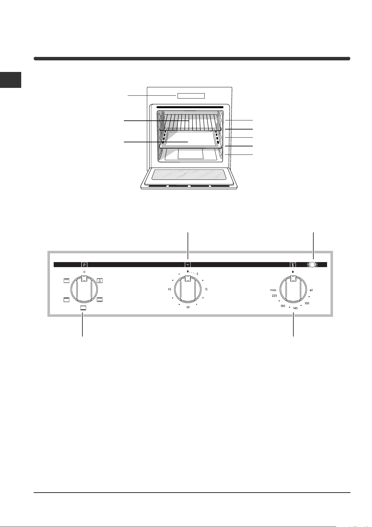
Overall view
Control panel
Control panel
GRILL
DRIPPING PAN
TIMER
Knob*
GUIDES for the
sliding racks
position 5
position 4
position 3
position 2
position 1
Indicator light
THERMOSTAT
SELECTOR
Knob
* Only on certain models
PLEASE PHONE US TO REGISTER YOUR APPLIANCE AND ACTIVATE YOUR PARTS GUARANTEE ON 08448 24 24 24
THERMOSTAT
Knob
4
 Loading...