

inDESIGN IDX-8FX, IDX-12FX, IDX-20FX, IDX-16FX Owner's Manual
iDX-FX SERIES: OWNER’S MANUAL
PAGE 2
• 4, 8, 12, 16 mono input channels with silver plated XLRs and
balanced line inputs. Ultra-low noise discrete mic preamps
with +48 V phantom power
• 2 stereo input channels with balanced TRS jacks
• Balanced inputs for highest signal integrity
• Ultra-musical 3-band EQ and FREQ control on all mono
channels and 3-band on all stereo channels. 4 LEDs on
all mono and stereo channels
• 2 aux sends per channel for external effects and monitoring
• Built in digital multi effects (32 bit 256DSP)
• Separate stereo master output, 2 group outputs, monitor
output and headphone outputs
• Highly accurate 2 x 10 segment bargraph meters
• Rugged design power supply ensures superior signal integrity
• Rack-mounting brackets included with iDX-8FX and iDX-12FX
Ultra Low Noise, 8/12/16/20-Channel
Mic/Line Mixer – INTRODUCTION
INTRODUCTION 2
IMPORTANT SAFETY
INSTRUCTIONS 3
A. OVERVIEW 4
B. INPUT CHANNEL 5
C. STEREO CHANNEL
INPUTS 7
D. MASTER CHANNEL 9
E. MIXER OUTPUT 12
F. POWER 13
G. INSTALLATION 13
H. CONNECTIONS 14
I. SPECIFICATIONS 16
J. WARRANTY INFO 17
CONTENTS
Electrical and Safety Warnings
THESE SERVICE INSTRUCTIONS ARE FOR USE BY QUALIFIED SERVICE PERSONNEL ONLY.
TO REDUCE THE RISK OF ELECTRIC SHOCK DO NOT PERFORM ANY SERVICING
OTHER THAN THAT CONTAINED IN THE OPERATING INSTRUCTIONS
UNLESS YOU ARE QUALIFIED TO DO SO.
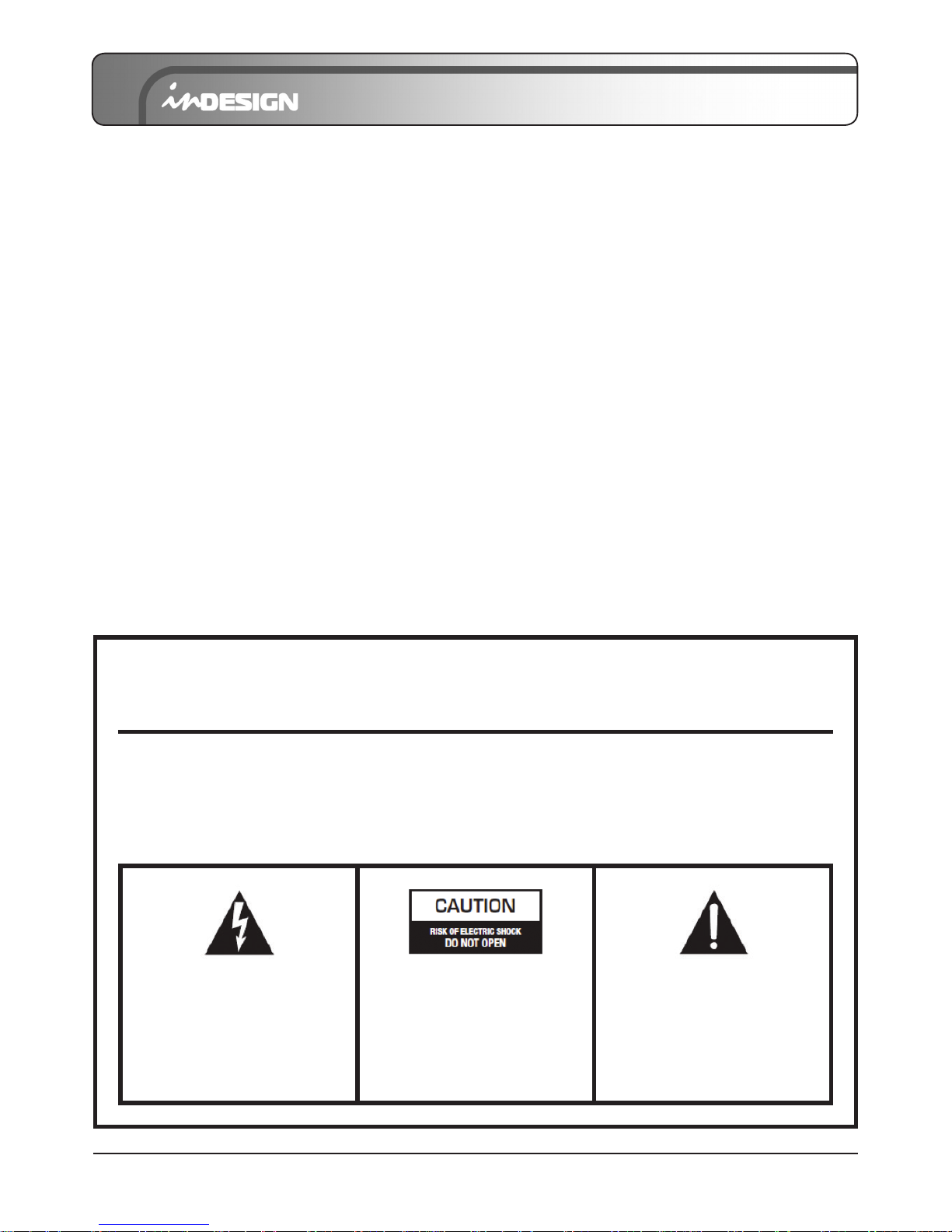
CAUTION
The lightening ash with arrowhead
symbol, within an equilateral triangle,
is intended to alert the user to the
presence of un-insulated
“dangerous voltage” within the products
enclosure that may be of sufcient
magnitude to constitute a risk of electric
shock to persons.
CAUTION: TO REDUCE THE RISK OF ELECTRIC
SHOCK, DO NOT REMOVE COVER (OR BACK).
NO USER SERVICEABLE PARTS INSIDE. REFER
SERVICING TO QUALIFIED SERVICE PERSONNEL.
WARNING: TO REDUCE THE RISK OF FIRE OR
ELECTRICAL SHOCK, DO NOT EXPOSE THIS
APPLIANCE TO RAIN OR MOISTURE.
The exclamation point within an
equilateral triangle is intended to
alert the user to the presence of
important operating and maintenance
(servicing) instructions in the literature
accompanying the appliance.
iDX-FX SERIES: OWNER’S MANUAL
PAGE 3
IMPORTANT SAFETY INSTRUCTIONS
1. Read these instructions.
2. Keep these instructions.
3. Heed all warnings.
4. Follow all instructions.
5. To prevent injury please refer to these instructions for electrical and safety information before installing
or operating the apparatus.
6. This apparatus must not be exposed to dripping or splashing liquid.
No object lled with liquid, such as a vase, should be placed on the apparatus.
7. Clean only with a dry cloth.
8. Do not block any of the ventilation openings. Install in accordance with the manufacturer’s instructions.
9. Do not install near any heat sources such as radiators, heaters, stoves, or other apparatuses
(including ampliers) that produce heat.
10. Unplug this apparatus during lightening storms or when not in use for long periods of time.
11. Protective Earthing Terminal:
The apparatus should be connected to a mains socket outlet with a protective earthing connection.
12. The mains plug/appliance coupler is used as a disconnect device, the disconnect device shall remain
readily operable.
13. When not in use and during transportation, please take care of the power cord set, for example,
tie up the power cord set with a cable tie/something similar. It should be kept away from sharp edges
and the like that can cause abrasion of the power cord set. When put into use again, check that the
power cord set is not damaged. If any damage is found, have the unit checked by a qualied service
person to replace the power cord set specied by the manufacturer.
14. The terminals marked with symbol of “ “ may be of sufcient magnitude to constitute a risk of
electric shock. The external wiring connected to the terminals requires installation by a qualied service
person or the use of ready-made leads or cords.
15. Only use attachments/accessories specied by the manufacturer.
16. Check speaker line load prior to connecting to amplier using an impedance meter.
17. Refer all servicing to qualied service personnel. Servicing is required if the apparatus has been
damaged in any way, such as power-supply cord or plug breakage, damage due to liquid or objects
falling onto the apparatus, exposure to rain or moisture, or if the apparatus does not operate normally,
or has been dropped.
18. Correct Disposal of this Product:
This marking indicates that this product should not be disposed with other household wastes throughout
Australia. To prevent possible harm to the environment or human health from uncontrolled waste
disposal, recycle it responsibly to promote the sustainable reuse of material resources. To return your
used device, please use the return and collection systems or contact the retailer where the product was
purchased. They can take this product for environmental-safe recycling.
WARNING: There are no user serviceable parts inside. Refer all servicing to qualied service personnel.

iDX-FX SERIES: OWNER’S MANUAL
PAGE 4
Here you can nd quick information on any feature on the console, along with a number reference
where you will nd a more detailed explanation.
A. OVERVIEW

iDX-FX SERIES: OWNER’S MANUAL
PAGE 5
B. INPUT CHANNEL
1. BALANCED INPUT (MIC)
Electronically balanced inputs accept a standard XLR
male connector. +48V phantom power available on each
input mic socket.
2. LINE INPUT
The unbalanced line input is provided for the
use of an unbalanced line input signal.
(This is used for connection of a CD/MP3 player,
keyboard, etc.)
3. PHANTOM POWER SWITCH
Depressing this switch for each channel applies 48V DC
for remote powering of condenser microphones. The LED
will be turned on when engaged.
4. LOW CUT
Push the switch to insert the 18 dB per octave 75Hz low cut
lter in the signal path. This low cut lter is useful on live vocals
to reduce stage rumble or “popping” from microphones. It can
also be used to cut off low frequency hum.
5. TRIM
This has a function which adjusts the input sensitivity of each
channel in order to input the constant level of the signal.
6. EQ ON
Leaving the switch up, the signal is not adjusted by EQ.
Pushing the switch down, the signal is adjusted by EQ.
7. HIGH
Control the high frequency tone of each channel. This control
should always be set to the 12 o’clock position however, you
can control the high frequency tone according to the speaker,
the condition of the listening position and listener’s taste.
Clockwise rotation of the control increases level.
8. FREQUENCY + MID
This equalisation has a “bell” response, i.e. Having reached
maximum amplication or attenuation at the selected
frequency, the amplitude response returns to zero either side
of that frequency. The FREQ at which this occurs is variable up
to 250Hz. The GAIN is variable between ±15dB at the selected
frequency with a xed Q of 1.5 (Q is a factor of bandwidth).
ONLY connect condenser microphones with the
+48V switch turned OFF and ONLY switch it ON with all
output faders DOWN to prevent damage to the mixer
or external devices.
iDX-FX SERIES: OWNER’S MANUAL
PAGE 6
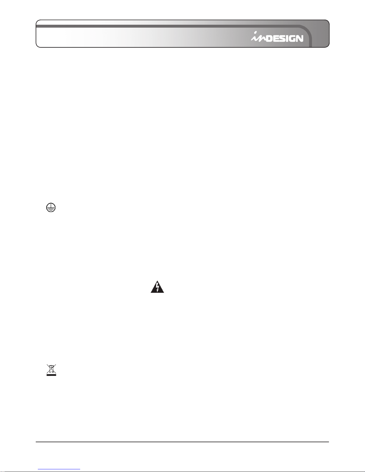
9. LOW
Control the low frequency tone of each channel. This control
should always be set to the 12 o’clock position however, you
can control the low frequency tone according to the speaker,
the conditions of listening position and listener’s taste. Clockwise
rotation of the control increases the level.
10. AUX 1
This is normally derived after the EQ section and channel fader
(PRE-FADER, POST-EQ) and is therefore unaffected by the fader
position and routing status. This makes the send particularly
suitable for foldback or monitor feeds, which need to be
controlled separately from the main PA mix. All pre-fade sends
may be selected internally to be PRE-FADE, PRE-EQ.
11. AUX 2
This is normally derived after the EQ and channel fader
(POST FADER, POST EQ), and therefore follows any changes
in fader level. They are normally used to drive effects processing
units which are fed back into the mixer and must fade out with
the input channel.
12. PAN
The pan control sends continuously variable amounts of the post
fader signal to either the LEFT or RIGHT and G1, G2 main busses.
In the centre position equal amounts of signal are sent to the
LEFT and RIGHT or G1, G2 busses.
13. STEREO L-R
Push this switch and the channels signal is routed
to the ST L-R fader.
14. G1-2
Push this switch and the channels signal is routed
to the G1-2 fader.
15. CHANNEL FADER
This is used to adjust the volume of signal connection into each
channel and adjust the volume of output, together with master
fader. Normal operating position is at the “0” mark and can also
provide an extra 4dB of gain above that point, if required.
16. PEAK
Top (red) LED indicates a signal level at the insert return
point, premaster fader, it illuminates at approximately 7dB
below clipping.
17. PFL
You can monitor the signal of a channel when this switch is on
by using a separate headphone. When the PFL switch is on, the
other channels mute automatically in the headphone mix. The
LED will illuminate when engaged.
 Loading...