

Independent Compressor Partners CA1U, CA1 Owner's Manual
Owners Manual
Owners Manual
8.5-15 HP Gas/Diesel Engine Drive
Reciprocating Compressors
Introduction
Congratulations on the purchase of your new air compressor. The air compressor is precision built from the finest
materials using the finest state of the art design, and high tech engineering available today. Quality, performance
and trouble free operation will assure you a dependable supply of air power on demand
Check www.icompressorpartners.com for most up to date manual and compressor service and technical information
CAUTION READ THIS MANUAL CAREFULLY before operating or servicing this air compressor, to
familiarize yourself with the proper safety, operation, and standard operating procedures of this unit.
FAILURE TO COMPLY WITH INSTRUCTIONS IN THIS MANUAL COULD RESULT IN THE VOIDING OF
YOUR WARRANTY, AND PERSONAL INJURY, AND/OR PROPERTY DAMAGE. THE MANUFACTURER OF
THIS AIR COMPRESSOR WILL NOT BE LIABLE FOR ANY DAMAGE BECAUSE OF FAILURE TO FOLLOW
THE INSTRUCTIONS IN THIS MANUAL. By following the instructions and recommendations in this man-
ual you will ensure a longer and safer service life of your air compressor.
Do not operate compressor outdoors in wet weather
Independent Compressor Partners, LLC
P.O. Box 206
Jeffersonville, IN 47131
Phone: 502.694.3595
www.icompressorpartners.com

8.5-15 HP Gas and Diesel Engine Driven Compressors
SAFETY PRECAUTIONS AND WARNINGS
Listed are some, but not all safety precautions that must be observed with compressors and
compressed air systems. Failure to follow any of these warnings may result in severe personal injury,
death, property damage and/or compressor damage.
Air from this compressor will cause severe injury or death if used for breathing or food processing.
Air used for these processes must meet OSHA 29 CFR 1910 or FDA 21 178.3570 regulations.
This compressor is designed for use in the compression of normal atmospheric air only. No other
gases, vapors or fumes should be exposed to the compressor intake, nor processed through the compressor.
Disconnect all power supplies to the compressor plus any remote controllers prior to servicing the
unit.
Relieve all pressure internal to the compressor prior to servicing.
Do not depend on check valves to hold system pressure.
A properly sized safety valve must be installed in the discharge piping ahead (upstream) of any shutoff valve (block valve), heat exchanger, orifice or any potential blockage point. Failure to install a
safety relief valve could result in rupturing or explosion of some compressor or safety component.
Do not change the pressure setting of the safety relief valve, restrict the function of the safety relief
valve, or replace the safety valve with a plug.
Over pressurization of some system or compressor component can occur, resulting in severe personal injury, death and property damage.
Never use plastic pipe, rubber hose, or soldered joints in any part of the compressed air system. Failure to ensure system compatibility with compressor piping is dangerously unsound.
Never use a flammable or toxic solvent for cleaning the air filter or any parts.
Do not attempt to service any part while the compressor is operating.
Do not operate the compressor at pressures in excess of its rating.
Do not remove any guards while the compressor is operating.
Observe gauges daily to ensure compressor is operating properly.
Follow all maintenance procedures and check all safety devices on schedule.
Compressed air is dangerous, do not play with it.
Use the correct lubricant at all times.
Independent Compressor Partners, LLC 502.694.3595 www.icompressorpartners.com

8.5-15 HP Gas and Diesel Engine Driven Compressors
WARNING: Never apply air pressure to compressor crank case, always make sure crank case vent
is clear and free from obstructions. Adding pressure to the crank case can cause serious bodily
injury or death.
WARNING: Never operate a compressor in a moving vehicle or towable object in motion. Doing
so can damage the compressor, compressor drive components, or auxiliary parts on the compressor package. Operating the compressor in a moving vehicle or towable object can cause serious
bodily injury or death.
WARNING: Check function of safety valves, weekly to insure proper function, replace immediately
if faulty or damaged.
Warning (Compressors Packaged with NEMA 7 Components)
Compressed Air Systems, LLC certifies that the electric motor, electrical enclosure and electrical
conduit are rated for NEMA7/hazardous locations. (Only for applicable packages with NEMA7
added components)
Air compressors have multiple moving parts and potential points of contact that could create
an ignition source. The compressor pumps are manufactured with ferrous metals and in some
cases multiple moving parts can come in contact with one another causing an ignition source.
Compressed Air Systems LLC does not guarantee this will not occur. Lack of maintenance or care
can result in conditions that could also cause ignition sources. Compressed Air Systems, LLC only
guarantees that the electric motor, electrical enclosure and electrical conduit are rated for NEMA7
hazardous location. Compressed Air Systems LLC accept no other responsibility for the rating of
the package.
Independent Compressor Partners, LLC 502.694.3595 www.icompressorpartners.com

8.5-15 HP Gas and Diesel Engine Driven Compressors
Troubleshooting Chart
NOTE: TROUBLESHOOTING PROBLEMS MAY HAVE SIMILAR CAUSES AND SOLUTIONS
Make sure drive engine battery is disconnected before any maintenance or repair
ALWAYS MAKE SURE COMPRESSOR DRIVE ENGINE KEY SWITCH IF OFF AND REMOVED FROM THE COMPRESSOR
You should always contact an authorized service center before attempting to fix or
repair your air compressor
Problem Possible causes Solutions
Compressor Stalls and Dies 1. Drive engine low on fuel
2. Compressor check valve not
functioning
3. Compressor Pilot valve not fun
ctioning
4. Spark Plug in Engine bad
5. Drive engine Low on oil
1. Check fuel level in drive engine
2. Inspect compressor check valve
3. Check drive engine spark plug
4. Check oil level on compressor
drive engine
5. Check oil on compressor pump
Compressor is running and is not
compressing air
Compressor does not idle up for
Compression
Compressor Pump Knocking 1. Loose motor pulley or
1. Compressor Pilot valve is
actuated
2. Compressor pilot valve is
malfunctioning
3. Compressors pump head
unloaders stuck engaged
1. Throttle control valve (bullwhip)
not engaging
2. Throttle control valve cable
broken
3. Drive engine throttle linkage
damaged
compressor flywheel
2. Low oil level in compressor
pump
3. Carbon build up on valve and
piston
1. Check pilot valve to make sure
it in the proper position
2. Replace compressor pilot valve
3. Check and clean compressor
pump head unloaders
1. Check throttle control valve
(bullwhip) for proper function
2. Replace throttle control valve
3. Check drive engine throttle
linkage
1. Tighten pulley or flywheel
2. Keep oil level at recommended
level for proper operation
3. Only use factory recommended
oil
Independent Compressor Partners, LLC 502.694.3595 www.icompressorpartners.com

8.5-15 HP Gas and Diesel Engine Driven Compressors
Troubleshooting Chart (continued)
NOTE: TROUBLESHOOTING PROBLEMS MAY HAVE SIMILAR CAUSES AND SOLUTIONS
Make sure drive engine battery is disconnected before any maintenance or repair
ALWAYS MAKE SURE COMPRESSOR DRIVE ENGINE KEY SWITCH IF OFF AND REMOVED FROM THE COMPRESSOR
You should always contact an authorized service center before attempting to fix or
repair your air compressor
Problem Possible causes Solutions
Excessive oil discharge in air (All
Compressors have a small amount
of oil carry over in compression
1. Worn piston rings or cylinder
2. Restricted air intake
3. Oil level to high
4. Compressor has exceeded it
duty cycle
1. Clean or replace air filters
2. Reduce oil level to
recommended amount
3. Reduce compressor duty cycle
(repair leaks or add another unit
to handle the excess demand)
Compressor Overheating 1. Poor ventilation
2. Dirty cooling surfaces
3. Compressor is out of its
operating duty cycle
Excessive Belt Wear 1. Pulley out of alignment
2. Improper belt tension
3. Pulley damaged of loose
Compressor wont start in Cold
weather
Compressor Has Excessive vibration 1. Compressor is not properly
1. Bad check valve
2. Compressor has wrong grade
oil
3. Control lines frozen
mounted on vibration isolation
pads
2. Compressor pulley is out of
alignment
3. Engine is low on fuel of throttle
is out of adjustment
1. Relocate compressor to any
area with better ventilation (at
least 18 inches from the nearest
wall)
2. Clean all cooling surfaces
3. Reduce compressor duty cycle
(repair leaks or add another unit
to handle the excess demand)
1. Realign pulley with flywheel
2. Re adjust belt tension
1. Use IS 100 (30W) compressor oil
for cold weather conditions
2. Move compressor to a warmer
location
3. Put a heat lamp on compressor
to maintain above freezing
temperatures
4. Properly mount compressor on
vibration isolation pads
5. Re-align pulleys
6. Check drive engine oil and fuel
level
7. Re-adjust engine throttle
control (bull whip)
Independent Compressor Partners, LLC 502.694.3595 www.icompressorpartners.com

8.5-15 HP Gas and Diesel Engine Driven Compressors
Compressor Maintenance
Warning: To avoid personal injury, always turn drive engine key off and remove
from compressor, relive all air pressure from the system, also disconnect the battery
power connections before starting any service or maintenance on the compressor
Daily:
Drain the Receiver- condensation will accumulate in
the tank daily, and should be drained at least once
a day. This is done to reduce corrosions of the tank
from the inside. Always wear protective eye wear
when draining the tank.
Check Pump Oil Level- All units have a sight glass the
oil level non running units should be no lower than
½ way on the sight glass if it is lower then you need
to add oil until it is at least ½ way up the sight glass.
Check unit for any unusual noise or vibrations.
Weekly:
Clean air filter: this will ensure that no dirt or heavy
particulate makes its way into the compressors valve
assemblies.
Clean external parts of compressor and electric motor: this helps to ensure proper cooling and prevents
rust and corrosion on critical parts.
Check safety Valves: this is don’t to ensure they are
not stuck in place and operating properly.
Elite Units Check auto tank drain for proper function
Every 3 months:
Change Oil: this is done to ensure that the compressor has proper oil level and that the oil in the
machine does not deteriorate past factory specifications.
Inspect Valve assemblies: this is done to prevent
premature failure and clean out and carbon that can
form in older valves.
*Elite Units. Clean auto tank drain strainer and check
for proper function.
Inspect pressure switch for proper function.
Inspect check valve for proper function and remove
any carbon accumulation to prevent premature
failure.
*Clean belt guard coolers (if equipped).
Storage of Compressor:
Before storing the compressor for a prolonged
period of time, use a blow gun to clean all debris
from compressor. Shut OFF main power and turn
OFF disconnect. Drain tank pressure, clean air filter,
drain old oil and replace with new oil. Cover the
unit to prevent dust and moisture from collecting
on the unit.
Monthly:
Inspect complete air system for leaks: this is done
to make sure the compressor does not get out of its
duty cycle due to air leak in the system.
Inspect Oil for Contamination: this is done to ensure
that harmful deposits do not build up in the oil.
Check belt tension: this is done to ensure the belt
do not fail pre-maturely, tighten them as needed
to ensure they do not slip. If belts are loose, tighten
per instructions on next page. Failure to tighten can
cause pre-mature belt failure.
Independent Compressor Partners, LLC 502.694.3595 www.icompressorpartners.com
If compressor is going to sit un-used for extended
periord of time (7 days or more) disconect battery
connections to ensure a longer batter life and proper
charge.
8.5-15 HP Gas and Diesel Engine Driven Compressors
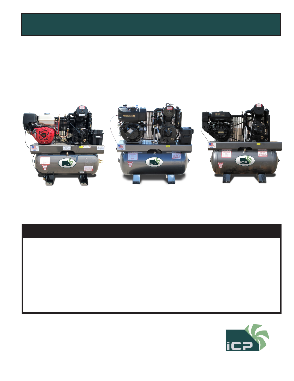
Adjusting Belt Tension
Proper belt tension and pulley alignment must be maintained for maximum drive efficiency and for maximum belt life. The correct tensions exists if a deflection of ½ inch occurs by placing 10lbs of force midway
between the motor pulley and the compressor flywheel. This deflection can be adjusted by the following
procedure. The pulley should be carefully aligned with the flywheel and set screws should be kept tight.
1. Remove the belt guard
2. Loosen the motor mounting bolts
3. Shift the motor to the point where the correct deflection exists
4. Retighten the motor mounting belts
5. Check to ensure that the tension remain correct
after tightening
6. Re-install the belt guard. All moving parts must
be guarded
NOTE: Drive belt tension and pulley alignment are done at the
same time. They are discussed separately for clarity.
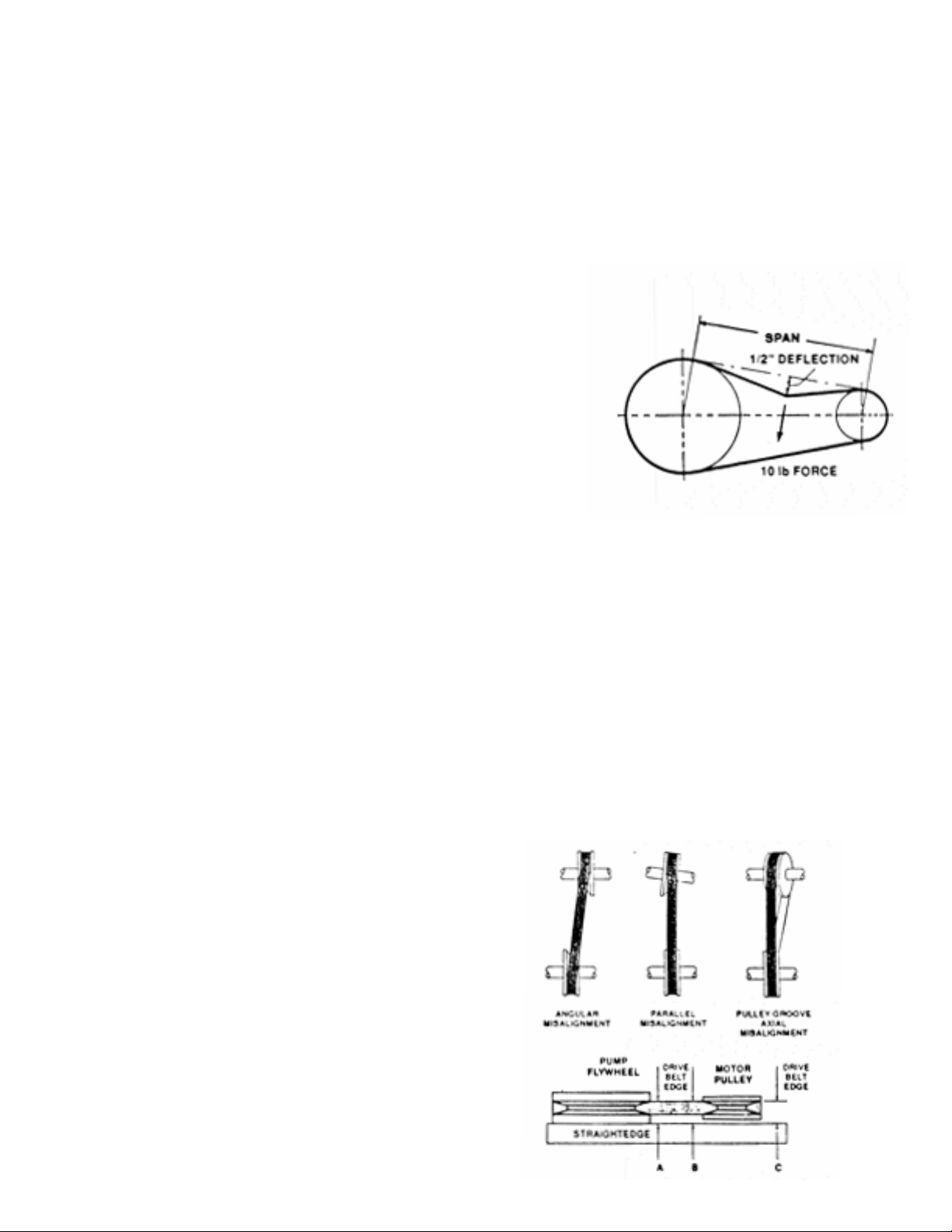
Pulley Alignment
The figure to the side shows 3 examples of misaligned pulleys. To check pulley alignment, remove the belt
guard and place a straightedge against the compressor flywheel, measure and record the distance from
the straightedge to the edge of the drive belt. Then measure the distance to the edge of the drive belt on
the motor pulley at the same edge. As long as both points measure the same distance the pulleys will be
aligned if not you will need to move the pulley until its in alignment this may take a few tries. To re-align the
pulley follow the steps below
1. Loosen the motor mounting bolts
2. Remove the belt guard
3. Loosen the set screw on the motor pulley
4. Align the motor pulley with the compressor flywheel
5. Re-tighten the motor pulley set screws
6. Adjust the proper belt tension
7. Re-tighten the motor mounting bolts
8. Re-install the belt guard
Independent Compressor Partners, LLC 502.694.3595 www.icompressorpartners.com

8.5-15 HP Gas and Diesel Engine Driven Compressors
Description of Compressor
What is a reciprocating compressor
A reciprocating compressor is a piston type pump which develops pressure from the action of a piston
moving through a cylinder. The cylinder, or cylinders, may be vertical, horizontal or angular.
When air is drawn in from the atmosphere and compressed to its final pressure in a single stroke, the compressor is referred to as a “single stage” pump. Single stage units normally are used in the 90 to 125 PSI
range and are available as single or multi-cylinder (twin cylinder) compressors.
When the air drawn from the atmosphere is compressed first to an intermediate pressure, and then further
compressed to a higher pressure, it is done in a “two stage” pump. These cylinders are unequal in size and
the first stage always takes place in the larger, low pressure cylinder. From there it passes through the inner
cooler to the smaller, high pressure cylinder. The cycle is completed as the air then moves through the after
cooler and discharge line into the tank. Two stage compressors are generally used for pressure ranges from
100 to 175 PSI and deliver more air per horsepower at these pressures. This increase in efficiency is partially
due to the heat dissipated as the air passes through the inner cooler.
Description Of Cooling
Our compressors are cooled by fan blades, incorporated into the driven sheave (pulley), blowing air across
the intercooler, after cooler, and cylinder head.
Description Of Controls
Stop/Start Receiver or plant air system pressure is controlled within limits by a pressure switch automatically stopping and starting the compressor as the air pressure reaches a maximum preset pressure (cut out)
and then drops to a minimum presser pressure (cut in).
Independent Compressor Partners, LLC 502.694.3595 www.icompressorpartners.com
 Loading...