

Independent ITC-3004 User Manual
Patent #4,912,755
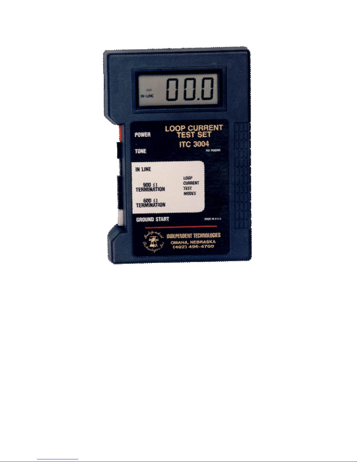
LOOP CURRENT TEST SET
ITC-3004 (Kit)
USER’S MANUAL
PLEASE READ BEFORE USING YOUR
3004 TEST SET

CAUTION: THE LOOP CURRENT TEST SET IS DESIGNED TO MEASURE
D.C. COMMUNICATIONS LOOP CURRENT ONLY. IT IS NOT A GENERAL
PURPOSE VOLT OHM METER. ATTEMPTING TO MEASURE A.C. VOLTAGE
OR CURRENT WILL DESTROY THE METER AND VOID THE WARRANTY.
i. GENERAL INFORMATION
Your tester is designed to help you test for normal telephone circuit operating
conditions before connecting terminal equipment to Central Office (C. O.) lines.
FCC guidelines specify that the telephone company should provide a minimum of
23 milliamps (ma) and a maximum of approximately 120 ms of D.C. loop current.
Most terminal equipment requires between 23 ma and 35 ma of loop current for
proper operation. (Special service circuits such as teletype, etc… may have
different loop current requirements.)
Less than 23 ma may cause poor transmission, ghost rings, wrong numbers and
other problems. The problems and the low loop current reading should be
reported to the serving telephone company.
More than 35 ma may cause problems such as cutoffs, repeated burn-out of Key
and PBX circuit packs, telephone instruments that need replacement for no
obvious reason, “squeal” and “hollow” sounds on the line, and other
malfunctions.
When high loop current is encountered, it is very important to adjust the D.C.
current down to an acceptable level in order to protect equipment and insure
optimum performance.
The ITC-4001 loop Attenuator, provided with this kit will reduce excessive D>C>
loop current without degrading the voice or data quality of the line. Additional
ITC-4001 Attenuators may be ordered from Independent Technologies.
YOUR LOOP CURRENT TEST SET PERFORMS
SEVERAL DIFFERENT CIRCUIT TESTS
A. LOOP CURRENT TERMINATION TEST
Measures D.C. Loop current by directly terminating the C.O. Line.
B. IN LINE TEST
Measures D.C. loop current in series with the C.O. line and the terminal
equipment during operation.
C. TONE TESTS
Your 3004 Tester generates two distinctively different warble tones which
may be used to troubleshoot loop problems or to locate cables.

II. USING YOUR TEST SET
A. LOOP CURRENT TERMINATION TEST:
1. Set the POWER SWITCH to the OFF position
2. Disconnect the premise equipment from the C.O. line.
3. Connect the C.O. line to the test set.
a. To test modular systems (AT&T Merlin, etc.), plug
the incoming C.O. line cord into the modular jack on
the test sel.
b. To test modular “ground start” systems:
1.) Insert the T-Adapter provided with the kit into
2.) Connect the line cord to the T-Adapter (line
3.) Connect the alligator cord to the T-Adapter
4.) Connect the red alligator lead to a local
c. To test non-modular systems, use the alligator clip
cord:
1.) Connect the green alligator clip to the “tip” side
2.) For “ground start” trunks, attach the yellow
4. Set the TERMINATION SWITCH to the 600 or 900 ohm
position.
Setting depends on how the trunk is optioned for loop length.
Systems without loop length options are assumed to be 600
ohm for test purposes. The guideline is 600 ohm for loop
lengths of less than one mile.
5. Set the POSER SWITCH to the ON position.
The test set screen will display the D.C. loop current reading
for the line being tested and the Termination Switch setting
(600 or 900 ohm).
For Ground Start trunks, momentarily press the GROUND
START SWITCH to draw dial tone from the C.O. and obtain
a reading.
the modular jack on the test set.
one jack).
(line two jack).
ground.
and the red clip to the “ring” side of the C.O.
line.
alligator clip to a local ground.
 Loading...