

Indeeco ZCA Series, XCA Series, TFZCA Series, TFXCA Series, ZCBA Series Installation, Operating And Maintenance Instructions
...
INSTALLATION, OPERATING AND
MAINTENANCE INSTRUCTIONS FOR
INDEECO ELECTRIC DUCT HEATERS
APPLICATION INFORMATION
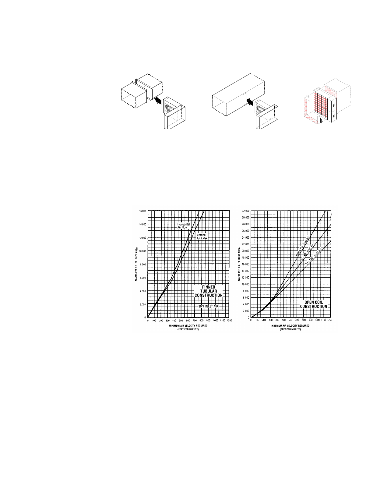
1. Follow the procedure given on the reverse side of this sheet
to find the minimum air velocity for safe operation. At least this
minimum velocity must be provided at all points over the heater
face area. Failure to meet this requirement may result in serious
damage or nuisance thermal cutout tripping.
2. The maximum air inlet temperature for open coil heaters is
100F (37.8C), and for finned tubular heaters, 80F (26.7C).
3. The heater must be located at least 4’ (1220mm) from any
grills, registers, filters, abrupt duct size changes, humidifiers, air
conditioning or air handling units, or any other change or
obstructions in the duct which may result in nonuniform airflow,
and not less than 30” (762mm) from the end of the warm air duct.
Duct elbows or turns must be located at least 4’ (1220mm) from
the inlet of the heater and 2’ (610mm) from the outlet of the heater.
Sufficient working space must be provided per paragraph 2-308 of
the Canadian Electrical Code.
4. These duct heaters are not intended for installation in series
in the airstream; the heaters are designed for use only as a single
unit within a duct with the exception of Series ZCA, XCA, ZCBA,
XCBA, TFZCA, TFXCA which are designed for stacked installation
for use as a single unit within a duct. (See Fig. No. 3)
MECHANICAL INSTALLATION
1. Heater terminal outlet box should not be enclosed. Heaters
with expanded metal terminal box covers must be installed in a
position where air passing out of the terminal box does not enter
into confined areas of the building structure (such as a space
behind a false ceiling, a hollow space in a wall, etc.)
2. All heaters are suitable for installation with zero spacing
between the duct and combustible surfaces.
3. The heater must be installed in the correct position as shown
by the arrows in the terminal box.
4. Sufficient clearance for convection cooling must be allowed
for all heaters with built-in SCR Power Controllers. Provide at least
5” (127mm) of free air space above and below cooling fins
extending from heater terminal box.
5. For proper operation of heaters equipped with a built-in
airflow switch, a minimum of .07” (1.8mm) WC of static pressure is
required in the duct system, and the velocity pickup tube for the
airflow switch must be pointed in the proper direction. When the
heater is installed on the downstream or positive pressure side of
the air moving fan, the arrow on the mounting flange of the pickup
tube must point in the same direction as the airflow. When the
heater is installed on the upstream or negative pressure side of the
air moving fan, the arrow must point in the direction opposite to the
airflow. If incorrectly installed, remove the two screws holding the
pickup tube in place, rotate 180 and reinstall. See separate
instruction sheet for installation of heaters supplied with a remote
pickup tube.
FOR FLANGE TYPE HEATERS ONLY: (See Fig. No. 1)
6. Provide flanges on the duct to match the heater flanges, both
on the entering and leaving air sides.
7. Attach the duct flanges to the heater flanges with bolts, sheet
metal screws or slip and drive connectors when the heater has
matching connectors for this purpose.
FOR SLIP-IN TYPE HEATERS ONLY: (See Fig. No. 2)
8. Cut a hole in the side of the duct to accommodate the body of
the heater (excluding terminal box). This hole should be 1/8”
(3.175mm) larger than the heater frame.
9. Slip the heater into the duct and attach the back of the terminal box to
the duct with sheet metal screws.
10. If heater has built-in PE switches they must be calibrated to field
control system. Calibrate the PE switch marked No. 1 to come on first.
FOR STACKED TYPE HEATERS ONLY: (See Fig. No. 3)
11. The heaters with catalog prefix ZCA, XCA, ZCBA, XCBA, TFZCA and
TFXCA must be stacked as indicated in Fig. No. 3.
FOR HEATERS TO BE INSTALLED IN FIBERGLASS DUCTS:
12. Write factory for special instructions. Note that the fiberglass duct
material itself must be CSA approved.
FOR HEATERS TO BE INSTALLED IN INTERIOR INSULATED DUCTS:
13. All slip-in type heaters are suitable for installation in ducts with up to
1” (25.4mm) of interior insulation as long as they have been sized for the
dimensions inside the insulation. The heaters are not suitable for
insulation depths of greater than 1” (25.4mm) unless a special construction
has been ordered. Flange type heaters are only suitable for installation in
insulated ducts if specially ordered for this application.
ELECTRICAL INSTALLATION
14. Follow the wiring diagram on the inside of the terminal box.
15. Supply connections must be made with copper wiring rated 90C
minimum. Use aluminum wire only when specifically called for on
accompanying wiring diagram.
16. All wiring in the terminal box must be insulated for 600 volts.
17. When making line connections to heater element terminals FOR
FINNED TUBULAR DUCT HEATERS ONLY, apply a ¼” wrench to flat
section of terminal or nut immediately below threads. Otherwise damage
to terminal may result.
18. Line connection should be based upon the line current and the
requirements of the Canadian Electrical Code. The line current for either a
single or three phase load is calculated as follows:
Single Phase Line Current=
KW x 1000
Voltage
Three Phase Line Current=
KW x 1000
Voltage x 1.73
19. Supply wiring must be suitable for 90C. Subject to local inspection
authority, current carrying capacity of supply wiring should not exceed
values shown in the Canadian Electrical Code Table 2, Col. 90C for not
more than three conductors in a raceway, in a 30C ambient or as
specified on the wiring diagram.
20. When connecting heaters with more than one stage, wire stage No. 1
so that it is the first stage on and the last stage off. Heaters with built-in PE
switches must follow this rule also. The stage number will be indicated on
the front of each PE switch.
continued installation etc.
21. The heater must be wired so that it
cannot operate unless air is flowing over
it. This can be accomplished by using a
built-in airflow switch, a built-in fan relay
or any of several other methods. See
the accompanying wiring diagram for
the method used with this heater and
provide appropriate interlock wiring as
illustrated.
22. The steady-state control circuit
load must not exceed the thermal cutout
pilot duty rating shown on the heater
nameplate.
23. When heater is not supplied with
built-in fusing, fuses must be installed in
accordance with the requirements of the
Canadian Electrical Code.
24. If not supplied as part of this
heater, install a line disconnect switch or
main circuit breaker in accordance with
the Canadian Electrical Code.
Depending upon the heater’s location
and accessibility, a built-in disconnect
switch may meet this requirement.
25. All electrical connections in the
heater, including both field and factory
made connections, should be checked
for tightness before operating the
heater. In addition, after a short period
of operation, all connections should
again be checked for tightness.
26. If heater is wired to a heatingcooling thermostat, use the thermostat
with isolating circuits to prevent possible
inter-connection of Class 2 outputs.
27. Magnetic contactors when used in
the primary limit control circuit of this
heater must be CSA approved for
250,000 cycle operation. Contactors
used in the secondary limit control
circuit on heaters rated 30 KW and less
must be CSA approved for 6,000 cycle
operation.
28. If heater frame is smaller than the
duct by more than 1” (25.4mm) in length
or width, the watts per square foot of
duct area should be calculated as the
heater nameplate watts divided by the
area inside the sheet metal enclosure
directly around the heating elements.
OPERATION & MAINTENANCE
NOTICE: ALL SOURCES OF SUPPLY MUST BE DISCONNECTED BEFORE WORKING ON THIS EQUIPMENT
To operate this heater make sure all associated control equipment is
on, energize main supply disconnect and set controlling thermostat
above ambient temperature. This heater is equipped with automatic
and manual reset temperature limit controls. If it fails to operate,
make sure manual resets are operative by pushing reset buttons.
Note: All metric conversions are approximate.
The only routine maintenance required is to check all electrical
connections, including field and factory made connections, for
tightness at least once each year or operating season. In addition, of
course, any filters in the airstream must be kept clean so that
adequate airflow is maintained.
INDUSTRIAL ENGINEERING & EQUIPMENT COMPANY
425 Hanley Industrial Court • St. Louis, MO 63144 USA • (314) 644-4300 • FAX (314) 644-5332
ENM - 2077 – 01 / 10-1081-83-4EF
INSTALLATION DRAWINGS
AIR FLOW REQUIREMENTS
Calculate watts per square foot of duct area as:
Heater nameplate watts
(See #28)
Duct area (Sq.Ft.)
Fig. 1 – Installation drawing
of flanged heater.
Fig. 2 – Installation drawing
of slip-in heater.
Fig. 3 – Installation drawing
of two stacked sections in a
duct.
 Loading...