

Page 1

Quartzone™
Infrared Quartz Tube & Metal Sheathed Electric Heaters
Owner’s Manual
File E97759
COMFORT HEATERS
for
INDOOR* and OUTDOOR** USE
*Excluding Residences
** With Quartz Elements and when mounted Underneath an Overhang by means of brackets out of the reach of persons.
This manual covers installation, operation and maintenance instructions. Read carefully
before attempting to install, operate or service.
www.indeeco.com
425 Hanley Industrial Court ♦ St. Louis, MO 63144
SAVE THESE INSTRUCTIONS
Page 1 of 6
59-2000-83
Page 2
IMPORTANT INSTRUCTIONS
Read Carefully - Installation and maintenance personnel should familiarize themselves with this
manual as it contains vital information for the proper installation, efficient operation and
maintenance of the heater described. Failure to follow these IMPORTANT INSTRUCTIONS
could result in fire, electric shock and injury to persons.
READ ALL INSTRUCTIONS BEFORE INSTALLING OR USING THIS HEATER
RISK OF FIRE / EXPLOSION
Electric Heaters are capable of developing
high temperatures and may contain arcing or
sparking electrical components. Extreme
care should be taken:
1. Risk of Fire and Explosion: This heater must not
be used in a hazardous location with any
flammable or explosive properties. Do not store
or use gasoline or other flammable vapors and
liquids in the vicinity of the heater.
For details on the particular hazardous environments
having the potential for explosion, refer to Articles 500
through 516 of the National Electrical Code, and/or
Section 18 of the Canadian Electrical Code Part I.
2. Avoid direct contact between heaters and
combustible materials. Keep combustible
materials such as furniture, pillows, bedding,
papers, clothes and curtains far enough away to
be free of the effects of high temperature.
Spacing should be at least 36” (914mm) from the
face of the heater or 12 inches (305mm) from any
other part of the heater.
3. Installation minimum mounting clearances
specified both on heater nameplate and in this
owner’s manual must be maintained.
4. Heater must not be recessed.
5. This heater has been evaluated by UL for
outdoor use only if mounted underneath an
overhang using a quartz heating element
6. Risk of Fire. For commercial and Industrial use
only. Do not use as a residential or household
heater.
RISK OF ELECTRIC SHOCK
Electric Heaters are appliances where
potentially lethal voltages are present.
Extreme care should be taken in the
installation, operation and maintenance
1. This Heater must be installed by qualified
personnel. Wiring procedures and connections
shall be in accordance with the national and local
codes having jurisdiction. It is the responsibility of
Page 2 of 6
the installer to verify the safety and suitability of
the installation.
2. Hazard of Electric Shock. Heater must be
grounded in accordance with the National Electric
Code (N.E.C) and/or the Canadian Electric Code
(C.E.C).
3. To disconnect heater, turn controls to off and
turn off power to heater circuit at main disconnect
panel.
4. Use this heater only as described in this manual.
Any other use is not recommended by the
manufacturer and may result in fire, electric
shock or personal injury.
5. Keep wiring and end reflector covers tightly
closed while in operation.
6. Do not operate this heater after a malfunction.
Disconnect power at service panel and have
heater inspected by a reputable electrician before
reusing.
RISK OF INJURY / BURN
Heater MUST be securely fastened to the
building structure to prevent it from falling.
It is the responsibility of the installer to verify
the safety and suitability of the installation.
1. Installation minimum mounting clearances
specified both on heater nameplate and in this
owner’s manual must be maintained.
2. Do not operate this heater after a malfunction.
Disconnect power at service panel and have
heater inspected by a reputable electrician before
reusing.
3. Do not insert foreign objects into the heater as
this may result in fire, electric shock, personal
injury or heater damage.
4. The heater is hot when in use. To avoid burns, do
not let bare skin touch hot surfaces.
5. Extreme caution is necessary when any heater is
used by or near children or invalids and
whenever the heater is left operating and
unattended.
59-2000-83
Page 3
INSTALLATION
These infrared heaters are designed for comfort heating. They
are to be permanently mounted to the wall or ceiling with the
fixture directed to the area to be heated. The unit is designed to
give years of safe, trouble-free operation when properly installed,
operated and maintained.
A. Site Selection:
The supporting structure where the heater is attached must have
adequate strength to safely support the heater. This heater has
been evaluated by UL for outdoor use only if mounted
underneath an overhang using a quartz tube heating element.
The heaters should not be mounted close to insulation, drapery
or similar materials which could come in contact with the cabinet
or heater guard. The heaters are intended for elevated mounting
locations so that they radiate down to the floor area. A mounting
height should be selected so that the heater has adequate
clearance to moving equipment and personnel, yet low enough to
deliver heat to the selected area. For heater weights and
minimum clearances, see tables 3 & 4:
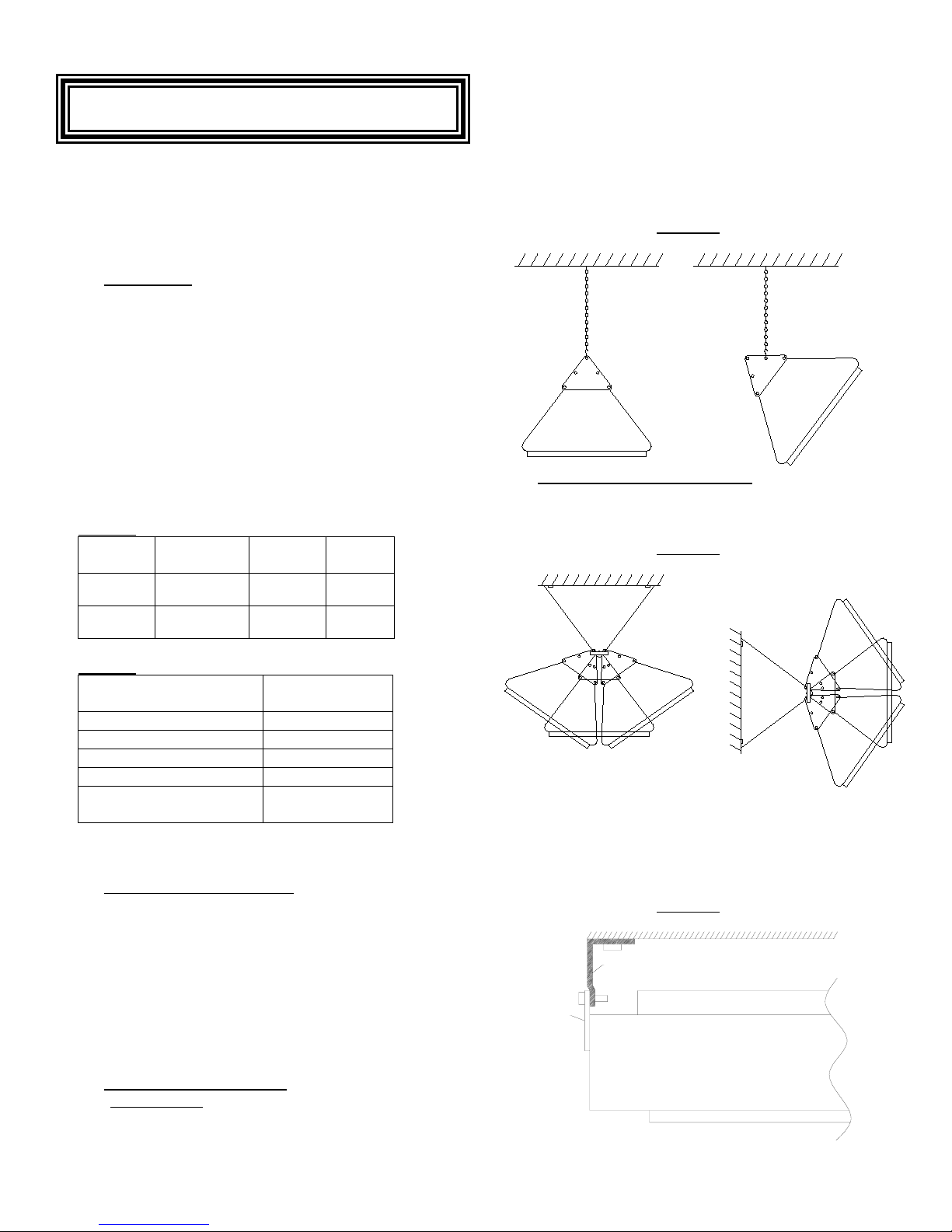
TABLE 3:
Fixture Length Max
1154 36” (914mm) 2000 10 lbs
1154A 61” (1549 mm) 4000 13 lbs
TABLE 4:
Location
Top of heater to ceiling 12 in (305 mm)
Bottom of heater to floor 6 ft (1.83 m)
Side or end of heater to wall 12 in (305 mm)
Heater to Adjacent Heater 36 in (914 mm)
Face of Heater to any
possible combustibles
Once an acceptable location has been determined, see the
following instructions to complete the mechanical installation:
B. Element Installation / Handling:
1. The heater fixture is shipped as an assembly with very
fragile quartz or metal sheathed heating elements
factory installed.
2. Replacement elements must be ordered separately to
be installed by a qualified person. See Section:
REPLACEMENT ELEMENT contained in this manual.
CAUTION: Do not handle the Quartz tube heating elements
with bare hands or with gloves that may have grease or oil
present.
C. Heater Mechanical Installation
Chain Mounting:
1. Fasten the two triangular mounting plates to
Weight
Watts
(4.5kg)
(5.9kg)
Minimum
Clearance
36 in (914 mm)
Page 3 of 6
the fixture with the screws provided. The dimple hole
should be kept towards the top.
2. Cut suspension chain to the desired length.
3. Attach the chain to the heater triangular brackets using
“S” hooks. S-hooks must be closed to assure the
heater is permanently mounted. Ensure heating
element is horizontal.
4. If desired, tilt heater by adjusting chains as shown in
figure 1:
FIGURE 1:
Bracket Mounting (Item HX-1025662):
The heaters may also be mounted by means of an optional
ceiling or wall mounting bracket as shown in figures 2, 3 &
4
FIGURE 2:
The brackets will register on studs or joists at 16”
centers. For the 36” (914mm) heater, the brackets should be
mounted with the flanges facing inward and the heater
triangular brackets located on the outer side as shown in
figure 3:
FIGURE 3:
MOUNTING
BRACKET
HEATER
TRIANGULAR
BRACKET
HEATER
(406mm)
59-2000-83
Page 4
INSTALLATION (continued)
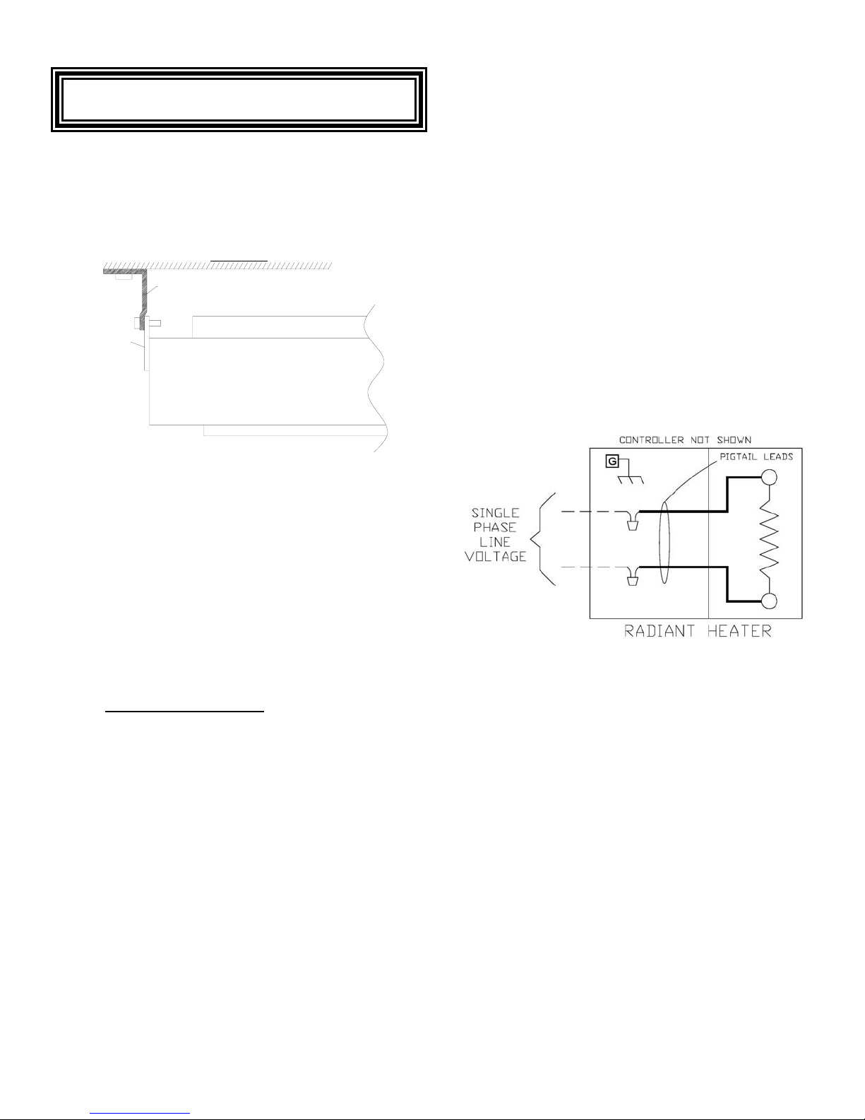
For the 61”
mounted with the flanges facing outward and the heater
triangular brackets located on the inward side as shown in figure
4:
(1549 mm) heater, the mounting brackets should be
HEATER
HEATER
TRIANGULAR
BRACKET
MOUNTING
BRACKET
FIGURE 4:
6. For general guidance in replacing elements or
changing to an alternate wattage element see the
section titled “
REPLACEMENT ELEMENT”.
7. Proper installation of the heater requires that an
adequate grounding conductor be connected to the
ground terminal. This terminal marked by a green
colored screw head and is located on the inside of the
wiring compartment.
8. Each heater is equipped with two high-temperature
silicone lead wires for connection to the power circuit.
Connect supply conductors to these two wires and
confirm all connections are securely tightened. Remove
any foreign objects from the control box and attach the
cover.
9. See typical wiring schematic below. In cases where
property damage may result from malfunction of the
heater a back-up system or temperature alarm should
be used.
10. Use 75ºC minimum copper conductors for wiring.
11. See section titled “OPERATION” before energizing the
heater.
The fixture can be directed into the area being heated by
adjusting the mounting brackets.
CAUTION: When directing the heater, care must be exercised to
prevent adjacent surfaces from overheating. Do not direct one
heater towards another. In no case, should any part of the
heater be less than 12”
Adjacent heaters should be no less than 36”
(305mm) to any wall or ceiling surface.
(914mm) apart.
CAUTION: The heater must always be mounted with the quartz
tube in a horizontal position. This will prevent the coiled
resistance wire from sagging and potentially failing.
CAUTION: The heater must not be recessed.
D. Heater Electrical Installation:
Follow these instructions to complete the electrical installation:
1. External branch circuit protection is required. See
heating element ratings and follow Code
recommendations.
2. Follow the NEC and any local electrical and building
codes related to the installation and intended use of the
heater.
3. When doing any work on this heater, including the
initial electrical connection, disconnect the electrical
supply at the main branch circuit switch, and lock the
switch in the off (open) position. Tag the circuit "Out for
Maintenance" to prevent potential lethal shock hazards.
4. Heaters are rated for single phase, 50/60 Hz power.
5. Confirm that the electrical power supply matches the
marked voltage and amperage for the heating element
which has been factory installed.
The heating element installed in the unit is
indicated either on the nameplate or on a
separate label adjacent to the nameplate.
Typical wiring schematic
Page 4 of 6
59-2000-83
Page 5
OPERATION
MAINTENANCE
1. Check to make sure the mechanical and electrical
installation is proper and complete and that it is safe to
operate the heater.
2. Set the field supplied temperature controller to a setting
above the current room temperature.
3. Energize the heater electrical supply circuit.
4. The heater should come on and have a visible radiant
glow within a few minutes.
5. Check out and report any unusual or questionable
operating characteristics, such as noise, smoke, etc.
6. Set the temperature controller and any secondary
safety devices to the desired room temperature setting
and place the heater in service.
7. Do not insert fingers or foreign objects into heater while
in service.
8. Do not tamper or attempt any maintenance with heater
while in operation.
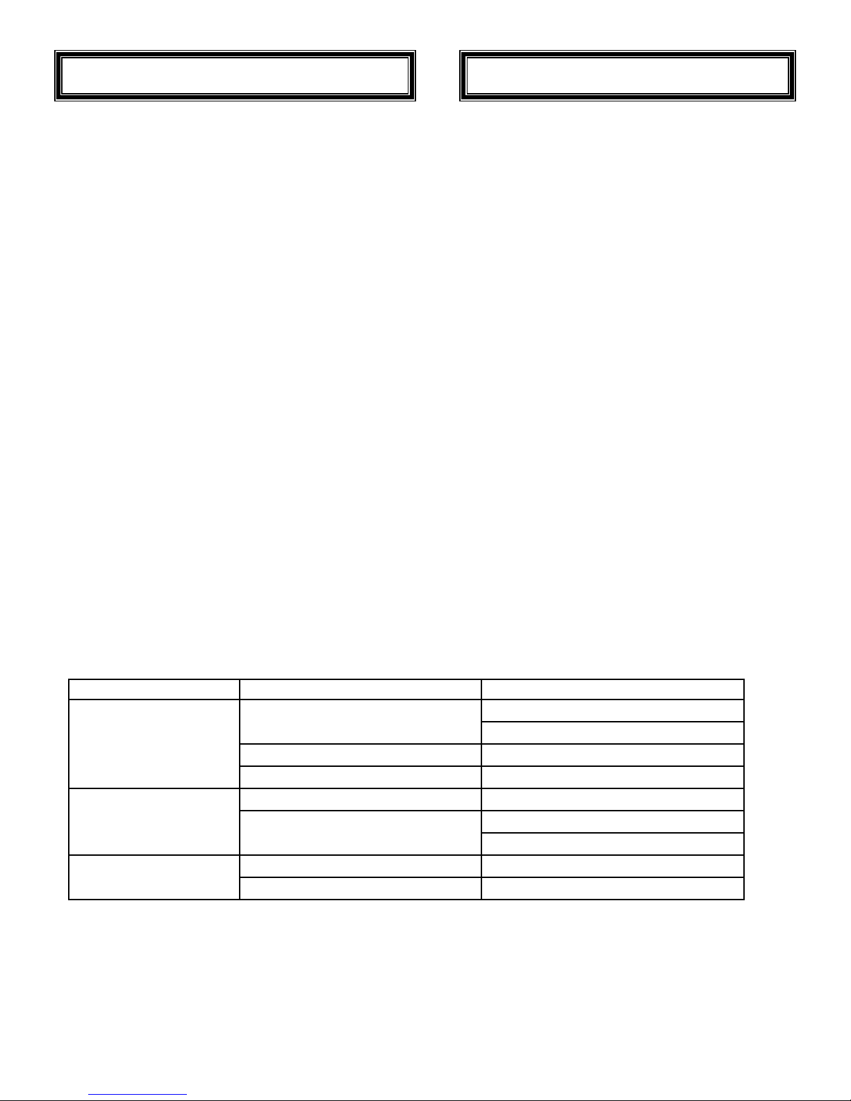
Troubleshooting Chart
SYMPTOM POSSIBLE CAUSE(S) SUGGESTION
1. Power not Supplied.
Heater does not energize
Not enough heat
Too much heat
2. Connection Inadequate 2. Check wiring connectors are secure.
3. Damaged Element 3. Replace Heating Element
1. Heater mounted too high or too far. 1. Carefully relocate heater
2. Heater too small for application
1. Heater too large for application. 1. Replace with lower KW Heater
2. Heater mounted too low or too close. 2. Carefully relocate heater
Maintenance and repair described in this section must be
performed by qualified personnel only. Any other Maintenance
should be discussed or performed by an authorized service
representative. At a minimum, all maintenance tasks should be
performed annually before each heating season.
1. When doing any work on this heater disconnect the
electrical supply at the main branch circuit switch, and
lock the disconnect switch in the off (open) position.
Tag the circuit "Out for Maintenance" to prevent
potential lethal shock hazards.
2. This heater is hot when in use, make sure the heater
has completely cooled off before attempting any
Maintenance.
3. Inspect all connections and conductor insulation for
damage, looseness, fraying, etc., as applicable.
Tighten any loose connections and replace or repair
wire with damaged or deteriorated insulation.
4. Check and Maintain the Clearance to Combustibles as
described in this manual.
5. Annually check the tightness of all visible screws, bolts
and nuts, in particular the support structure including
chains or bolts and nuts. Make sure the heater is
secure on all supporting points.
6. Check the wiring compartment for cleanliness. If
necessary, clean by using a vacuum or compressed
air.
7. The heater will operate at maximum efficiency when
the reflector and heating element are kept clean. The
reflector can be removed by snapping out one edge
and rotating. Most dust and dirt can be removed by
washing the reflector and heating elements with a 5050 mixture of rubbing alcohol and water. Dry thoroughly
before energizing.
1a. Check Branch Circuit fuse or Circuit Breakers.
1b. Check the status of any controls.
2a. Add additional Heaters
2b. Replace with higher KW Heater
Page 5 of 6
59-2000-83
Page 6
REPLACEMENT ELEMENT
WARRANTY WILL BE VOID IF INSTRUCTIONS ARE NOT FOLLOWED.
Quartz Tube / Metal Sheath Element Installation:
Replacement elements which must be ordered separately are to be
installed by a qualified person. Wiring procedures and connections
shall be in accordance with the national and local codes having
jurisdiction.
CAUTION:
turn controls to off and turn off power to heater circuit at main
disconnect panel. Lock the disconnect switch in the off (open)
position. Tag the circuit "Out for Maintenance" to prevent
potential lethal shock hazards. ‘
CAUTION:
sharp edges and fragments. Use extreme care when handling
broken tubes or when handling new replacement elements.
1. Remove the wire guard from the heater cabinet by
2. Remove the two end reflectors held in place by 2 screws
3. Remove existing heating element. First, note the caution
4. Remove the quartz or metal tube heating element from its
5. Verify the correct heating element is being installed for
Refer to the instructions below:
6. For quartz tube heating elements: A paper wrapper is used
Before removing or replacing a heating element,
Quartz Elements can fracture and produce very
springing out to one side.
each.
statement below.
CAUTION:
hazard. The material may chip and crack as with glass to
produce very sharp edges and fragments. Use appropriate
measures to protect skin and eyes to reduce the risk of
personal injury. When disposing of heating elements use
caution and comply with local and state regulations.
packaging. Do not pull the quartz element by the white
ceramic terminal insulator.
CAUTION
elements with bare hands or with gloves that may have
grease or oil present.
replacement.
to keep debris away from the quartz tube during shipping
An old quartz heater should be treated as a
: Do not handle the Quartz tube heating
a. The wattage, voltage and part number of the
replacement heating element should be
compared with the markings on the heater and/or
the wattage, voltage and part number from the old
element.
b. If electrical ratings or part number differ contact
an authorized factory service representative.
and installation. Leave the paper wrapping in place until
the element is completely installed to prevent finger marks
and/or grease and oil from transferring to the quartz tube.
7. Carefully push the element into the two clips in the end
castings.
8. Attach the lead wires to the heater terminals.
CAUTION
ensure the terminals do not twist by holding the inner nuts
when tightening the outer nuts.
9. For quartz heating elements: Remove wrapping paper.
CAUTION
from quartz heating element will result in Fire.
10. Replace end reflectors and wire guard.
11. Refer to the operation section of owner’s manual.
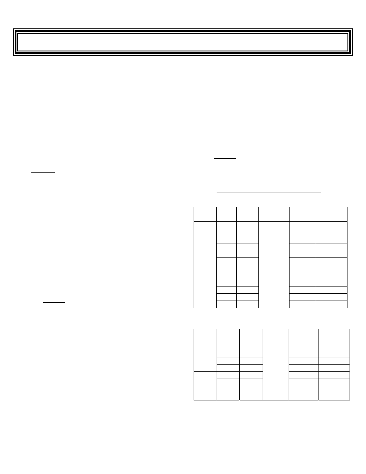
Replacement Element Specifications
TABLE 1 – Fixture 1154 Heating Elements:
Watts Volts Amps
1000
1500
2000
TABLE 2 – Fixture 1154A Heating Elements:
Watts Volts Amps
3000
4000
: When tightening the nuts on the terminals,
: Risk of Fire: Failure to remove paper wrapping
Heater
Length Quartz
120 8.3 QT-10L QM-10L
208 4.8 QT-10V QM-10V
240 4.2 QT-10N QM-10N
277 3.6 QT-10Y QM-10Y
120 12.6 QT-15L QM-15L
208 7.2 QT-15V QM-15V
240 6.3 QT-15N QM-15N
277 5.4 QT-15Y QM-15Y
208 9.6 QT-20V QM-20V
240 8.3 QT-20N QM-20N
277 7.2 QT-20Y QM-20Y
480 4.2
208 14.4 QT-30N QM-30V
240 12.6 QT-30V QM-30N
277 10.8 QT-30Y QM-30Y
480 6.3 QT-30Z QM-30Z
208 19.2 QT-40N QM-40V
240 16.6 QT-40V QM-40N
277 14.4 QT-40Y QM-40Y
480 8.3
36 “
(914mm)
QT-20Z QM-20Z
Heater
Length Quartz
61”
(1549 mm)
QT-40Z QM-40Z
Sheathed
Metal
Metal
Sheathed
SAVE THESE INSTRUCTIONS
Page 6 of 6
59-2000-83
 Loading...