

Indeeco OTL221, OTL222 Installation Instructions Manual
SAVE THESE INSTRUCTIONS
INSTRUCTIONS
Thermostat is suitable for electric heating systems.
Power Supply AC 120V / 208V / 244V / 277V
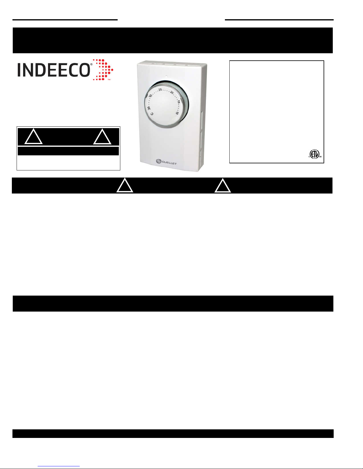
OTL221/OTL222
Thermostat
!
ELECTRIC SHOCK OR FIRE HAZARD
READ ALL WIRE SIZING, VOLTAGE REQUIREMENTS AND
SAFETY DATA TO AVOID PROPERTY DAMAGE AND
READ CAREFULLY -
money later. Observing the following procedures will keep installation time to a minimum. Save these instructions for future use.
FUNCTIONS AN D FEATURES
DANGER
PERSONAL INJURY
These instructions will help prevent di culties that might arise during thermostat installation. Studying the instructions rst may save considerable time and
!
!
WARNING
Maximum Power:
2640W @ 120VAC (22A)
4576W @ 208VAC (22A)
5280W @ 240VAC (22A)
6094W @ 277VAC (22A)
Sensing Element: Bimetal
Temperature Operating Range:
41°F-90°F (5°C—32°C)
cETL us listing.
!
Specica tions:
120/208/240/277 Volts
Both °C & °F control dials included
Wall mount design– Sits ush against wall
Single-pole and Double-pole models available
INSTALLATION INSTRUCTIONS
Warning: Turn OFF the power at the circuit breaker before Installing.
Installation should be performed by a qualied electrician.
Refer to thermostat and heater load specications before installation of the
thermostat to see if it can handle the amp load. The maximum this
thermostat can run is 6094 Watts at 277 Volts, 5820 Watts at 240 Volts,
4576 Watts at 208 Volts and 2640 Watts at 120 Volts.
Fully vented cover allows air sensing in all directions
Large knob allows easy adjustment to all temperatures
Beveled face gives modern appearance
90°F (32°C) maximum setting
Install unit in a grounded metal or plastic wall junction box, indoors 4 ½ ft.
to 5 ft. above the oor. Avoid any area where it can come in contact with
external sources of heat and cold. This includes plumbing pipes, direct
sunlight, a T.V. set, lamps, and drafts from a door or window, as this may
cause inaccurate temperature readings. The most convenient place is above
the light switch. Not for Outdoor use.
INDEECO · 425 Hanley Industrial Court · St. Louis, MO, 63144 · PH: (314) 644-4300 · FAX: (314) 644-5332 · www.indeeco.com
1
SAVE THESE INSTRUCTIONS
INSTALLATION INSTRUCTIONS CON’T
!
ELECTRIC SHOCK OR FIRE HAZARD
READ ALL WIRE SIZING, VOLTAGE REQUIREMENTS AND
SAFETY DATA TO AVOID PROPERTY DAMAGE AND
DANGER
PERSONAL INJURY
!
The installation of the thermostat must comply with the applicable local and/or national electrical code and
utility requirements. This installation should be performed by a qualied electrician where required by law.
Ensure that all wiring connections to the thermostat are correct and tight to prevent electrical shorts. Use the
appropriate wire to meet local and national electrical codes for rated power consumption.
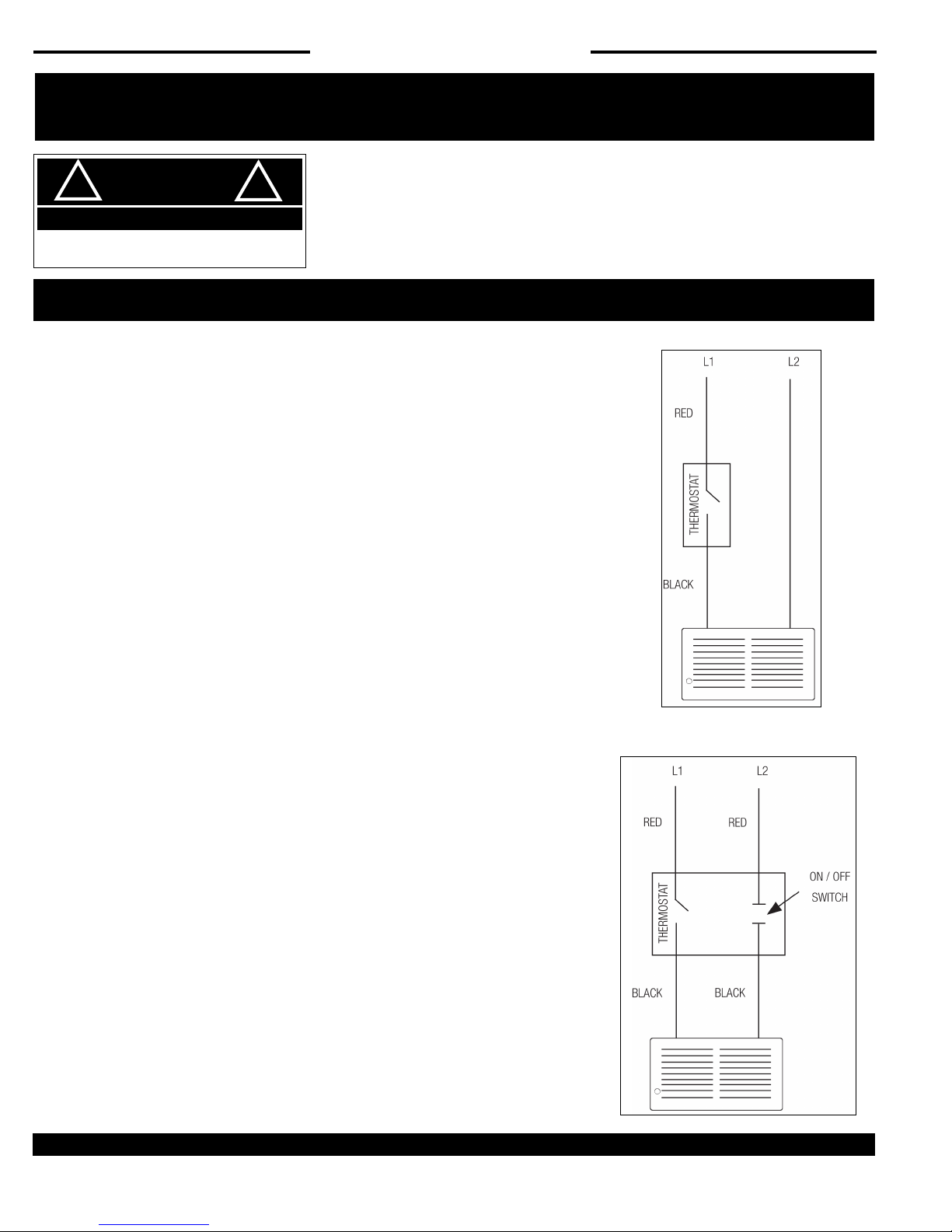
WIRING INSTRUCTIONS
Single-pole Thermostat Installation
1. Disconnect power supply to prevent electrical shock or damage to the product.
2. Run line voltage wiring to the location of thermostat.
3. Connect the red LINE lead on the thermostat to L1 line from the power supply
panel.
4. Connect the black LOAD lead from the thermostat to the line lead on the heater.
5. Connect N Neutral ( L2) line to the remaining line of the heater.
6. Secure the ground wire to the ground screw provided in the junction box.
7. Make sure wire connections are tight.
8. Insert wires into the junction box, making sure not to damage wiring.
9. Remove the thermostat cover by grabbing the cover from the sides and pulling it
away from base.
10. Mount the thermostat base onto the junction box and secure using the provided
screws.
11. Replace thermostat cover.
Sing le-pol e
In sta llatio n
Double-pole Thermostat Installation
1. Disconnect power supply to prevent electrical shock or damage to product.
2. Run line voltage wiring to the thermostat location.
3. Connect the black LOAD leads on the thermostat to the leads on the heater.
4. Connect the red LINE leads on the thermostat to the line leads from the power supply
panel.
5. Make sure all connections are tight.
6. Insert wires into the junction box, making sure not to damage wiring.
7. Secure the ground wire to the ground screw provided in junction box.
8. Remove the thermostat cover by grabbing the cover from the sides and pulling it away
from base.
9. Mount the thermostat into the junction box and secure using the provided screws.
10. Replace thermostat cover.
INDEECO · 425 Hanley Industrial Court · St. Louis, MO, 63144 · PH: (314) 644-4300 · FAX: (314) 644-5332 · www.indeeco.com
Do uble-p ole
In sta llatio n
2
 Loading...