

Indeeco 961, 961-U5000V-T, 961-U5000K-T, 961-U5000U-T Series Manual
961 SERIES
EXPOSED
EXPOSED
H
H
H
H
H
EXPOSED
EXPOSED
CONFINED SPACE
UNIT HEATER
Horizontal or Vertical Mounting
ATTENTION: Read carefully before attempting to install or
operate Unit Heater.
FEATURES:
• Forced air electric unit heater available in:
240/208 volt single phase, 5 kw and
240 and 480 three phase 5 kw.
• 240/208 single phase unit is factory wired
for 5 kw. The wattage may be changed by
moving jumpers as indicated in table 1.
• 24 volt control standard on three phase unit.
• All units with “T” sufx provided with unit
mounted hydraulic thermostat.
• Mounting bracket included with all units.
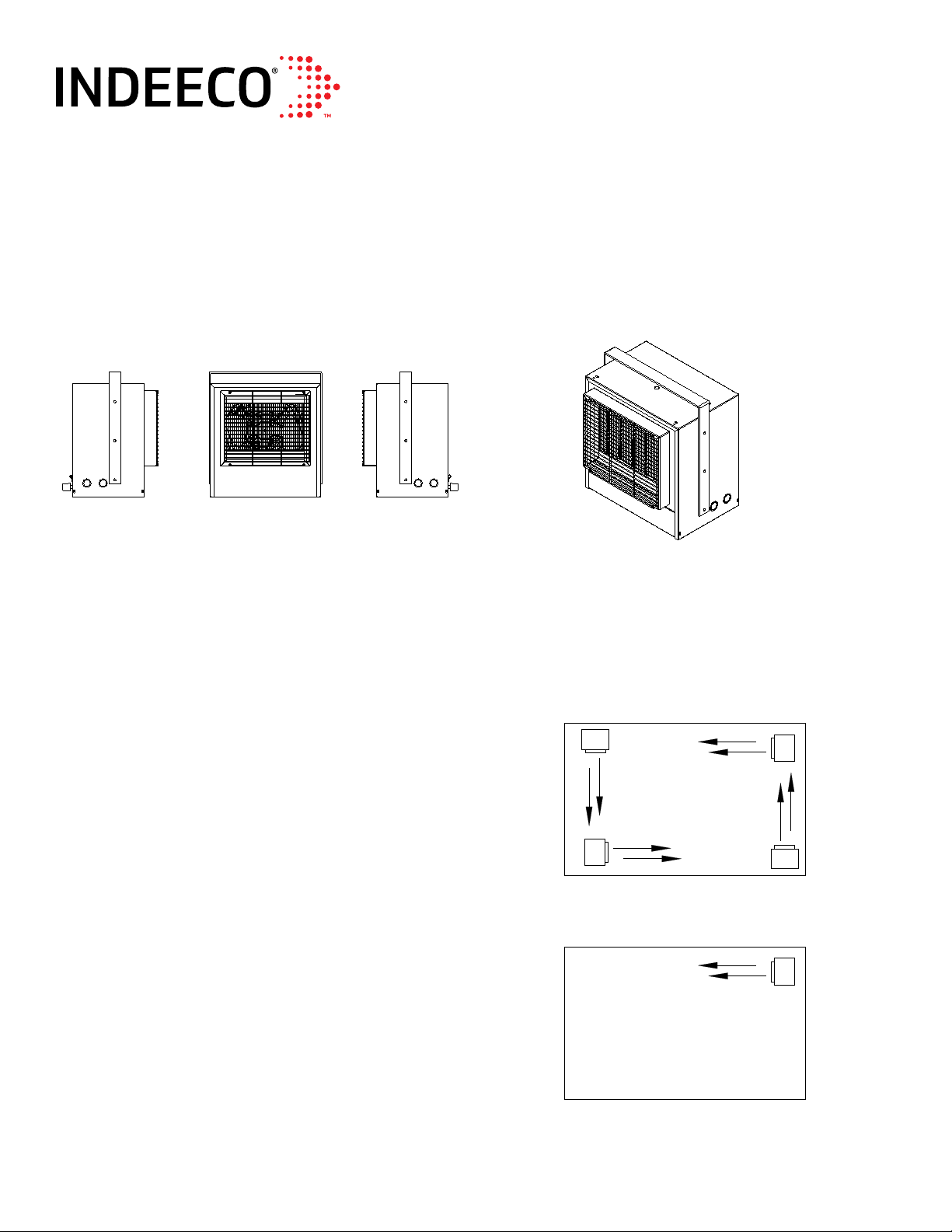
PROPER MOUNTING:
The heater(s) should be located along outside
walls or other areas of greatest heat loss.
Multiple heaters should be spaced to set up a
generally circular air movement, each heater
supporting the air stream of the other.
IMPORTANT: OWNER SHOULD RETAIN THESE INSTRUCTIONS FOR FUTURE REFERENCE
REV. LEVEL ECO 1-7305 07/2017 FORM 9763
PRINCIPLES OF OPERATION
When the thermostat calls for heat, the elements
are immediately energized, a fan delay brings on
the fan after the elements are heated allowing
warm air to circulate. When the thermostat is
satised, the elements are de-energized and the
fan purges the heater of residual heat.
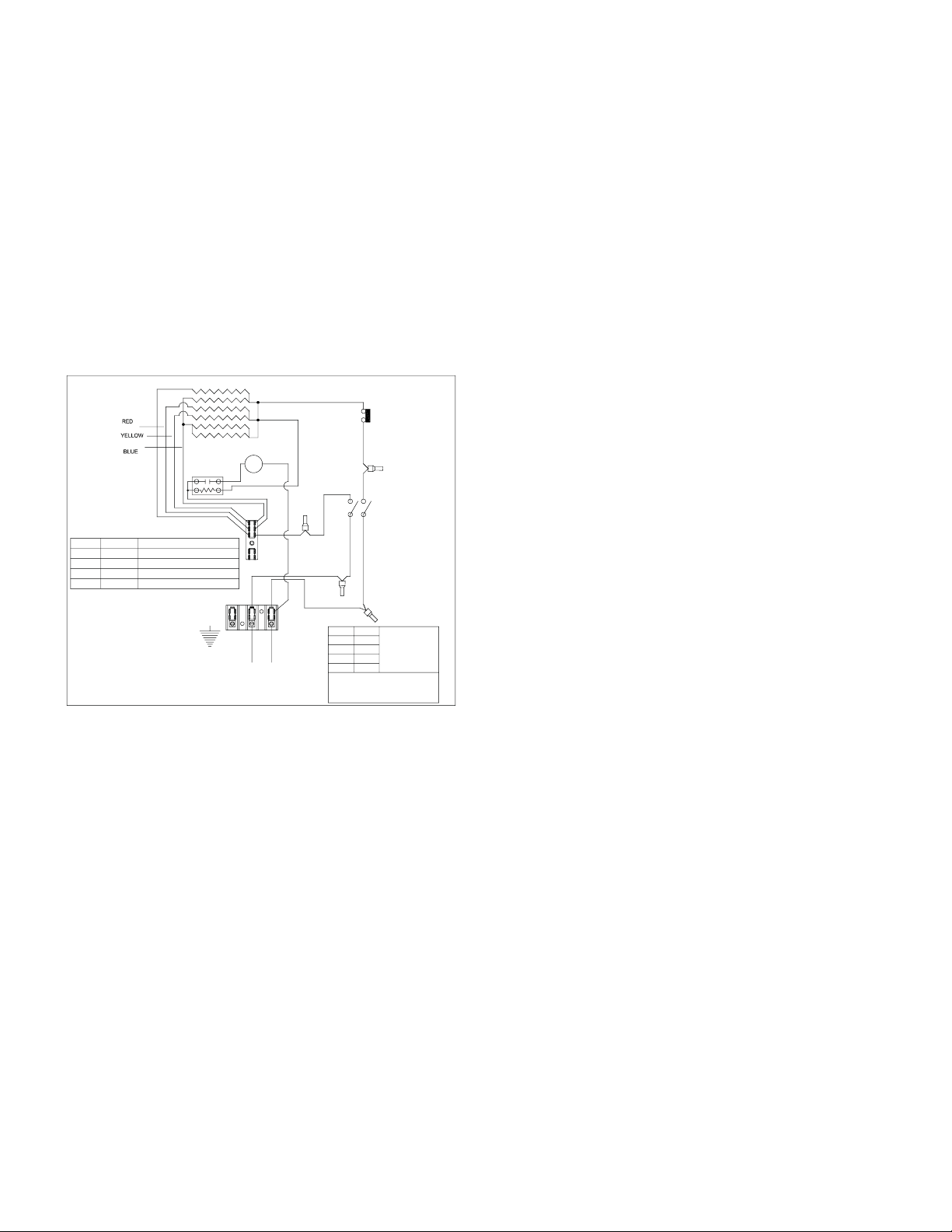
The heater wattage may be eld adjusted only on
model 961-U5000V-T. Select the desired wattage
from Fig.1 and move color coded jumpers as
indicated.
ELEMENT
LIMIT
CONTROL
M
A
C
B
L1 L2
240/208V 1
BLACK
RED
THERMOSTAT
RED
BLACK
LTB
AWG
14
12
10
8
CAUTION: USE SUPPLY WIRES SUITABLE FOR
PH
D'APPROVISIONNEMENT APRÈS AU MOINS 90 ° C
AMPS
12
USE COPPER
16
CONDUCTORS
ONLY
24
36
AT LEAST 90°C (194°F)
ATTENTION: UTILISEZ DES FILS
(194 ° F)
WATTAGE ADJUSTMENT TABLE
VOLTS
WATTS
240/208
4167/3120
240/208
240/208
240/208
2500/1875
USE COPPER CONDUCTORS ONLY
CONTROL CIRCUIT WIRING MUST BE
NEC CLASS 1 RATED 600V
USE WITH MODEL NUMBER
961-U5000V-T
ADJUSTMENT
NONE REQUIRED5000/3750
BLUE JUMPER TO TERMINAL 'C'
BLUE AND YELLOW TO TERMINAL 'C'3333/2500
BLUE,YELLOW AND RED TO TERMINAL 'C'
FAN DELAY
MOUNTING THE HEATER
Select the mounting location. Be sure to observe
the minimum mounting clearances as shown in
Figure 2.
The heater can be mounted either from the
ceiling or wall depending on the application.
The mounting bracket is supplied with 3/8” holes,
10 inches on center for threaded rod mounting or
direct mounting to the structure.
The heater cabinet also has 3/8” weld nuts 10” on
center to allow threaded rod mounting without the
bracket.
1. Install the mounting bracket in the desired
location with threaded rod or hardware
that is appropriate for the mounting surface.
If using threaded rod, two nuts, one on the top
and one on the bottom of the bracket along
with a split washer is suggested.
2. Secure the heater to mounting bracket, using
the 1/4-20 x 3/4” machine screws and
lockwashers provided.
3. Position the heater, aligning the bracket holes
with the cabinet holes and secure bracket to
the cabinet with the 1/4-20 x 1/2” machine
screws and nuts that are provided. With the
mounting bracket in the vertical position the
1/4” nuts are not necessary, weld nuts are
supplied in the cabinet.
Fig.1
INSTALLATION INSTRUCTIONS
All electric unit heaters are shipped fully
assembled. Installation includes hanging the
unit and electrical wiring to the unit.
The wall and/or ceiling structure must be
sufcient to support the combined weight of the
heater and any mounting bracket and
accessories.
Be sure power source is de-energized before
installing heater. Check heater voltage and
phase listed on heater data label on back of unit
to make sure they are the same as the electrical
service supplied.
REV. LEVEL ECO 1-7305 07/2017 FORM 9763
 Loading...