

Page 1

781 SERIES STORAGE TANK HEATERS
INSTALLATION, OPERATING &
MAINTENANCE INSTRUCTIONS FOR
GENERAL
INDEECO Storage Tank Heaters are designed to provide
years of trouble free operation if properly installed and
maintained. Please read and follow these instructions for
installing and maintaining the heater.
Storage Tank Heaters provide an effective way to heat large
storage tanks. The heating element design allows removal
and servicing of the heating element without draining the
tank.
HEATING ELEMENT CONSTRUCTION
The heating elements are open coil design and consist of
heavy gauge nickel-chromium alloy supported by ceramic
insulators. The ceramic insulators are fastened to a strip of
heavy sheet metal.
PIPE ASSEMBLY CONSTRUCTION
The heating elements are installed in 3” NPS pipes of
sufficient wall thickness to prevent the pipe from distorting
from the heat generated. The pipes are constructed so that
the heating elements may be removed without draining the
tank. Multiple pipes are provided as required. The heater is
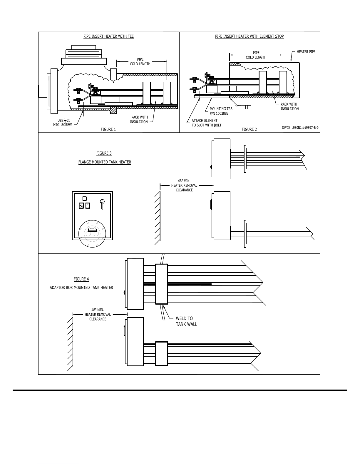
mounted to the tank by one of three methods: ANSI flange
mount, INDEECO adapter box, or with a custom rectangular
flange.
A built-on terminal box is provided with pre-wired controls for
proper heater operation. When requested, controls may be
remote mounted. Refer to IOM 87-2000-83 for remote
Industrial Control Panels.
The heater watt density and design features must be closely
matched to the application. Life of the heating element is
directly related to its surface temperature.
INSTALLATION
INDEECO recommends installation be performed by
qualified personnel familiar with the National Electrical
Code and all local codes and standards. It is the
responsibility of the installer to verify the safety and
suitability of the installation
DO NOT mount heaters in an atmosphere containing
combustible gases, vapors, dusts, or fibers unless properly
marked as suitable for the condition. Refer to section
below for special instructions for Hazardous Areas.
Hazardous voltages are present in this equipment. Lock
out and tag the branch circuit disconnect switch before
working on this heater.
CAUTION
WARNING
WARNING
Failure to follow INDEECO recommendations could
result in premature failure and/or serious equipment
damage.
Temperature regulating devices, temperature limiting
controls, and low liquid level controls are recommended for
use with Storage Tank Heaters, to control the heating
process and safeguard the heater from excessive
temperatures that can cause damage. Also, damage to fluid
could occur if the heater is allowed to exceed the maximum
film temperature recommended by the manufacturer.
INDEECO Storage Tank Heaters can be specially designed
for use in hazardous areas as specified in Article 500 through
516 of the National Electrical Code. Refer to the heater
nameplate or INDEECO Application Data for classification of
the heater provided. See section below labeled Hazardous
Areas for specific requirements.
It is the ultimate responsibility of the user to verify that
the construction materials provided by INDEECO are
suitable for use with the process fluid. Specifically,
corrosion issues must be reviewed. Refer to INDEECO
Application Data for heater construction materials and
design conditions.
For additional product offerings, refer to INDEECO catalog
literature on Process Heating such as Circulation Heaters,
Immersion Heaters, or Tubular Heating Elements.
Handling and Storage
Care must be taken to avoid damage to the heater during
storage and handling. The Pipe Insert Heater elements are
constructed of ceramics that can be damaged if not handled
carefully.
Protect the heater from weather damage during storage.
It is recommended to store the heater in a cool dry area to
help prevent the heating element ceramic spacers from
drawing moisture.
1
CAUTION
Page 2
Mechanical Instructions
p
g
Site Selection
Review the NEMA Type rating of the heater noted on the
INDEECO Application Data. Do not install a heater in an
area not consistent with its rating. The standard configuration
provided is NEMA Type 4, intended for outdoor use.
Allow sufficient free space around heater installation site.
Work space for heater maintenance should be at least three
feet in front and on either side of the heater. The minimum
pull space for the heating element installation or removal from
the pipe/tube should be at least four feet. The heating
element is designed to be flexible and can be curved if
necessary.
Leave a minimum of 6” clearance to any SCR heat sinks
mounted through the side of panels to allow proper cooling.
Electric heaters are capable of developing high temperatures.
Therefore, extreme care should be taken to
avoid mounting heaters in an atmosphere containing
combustible gases, vapors, dusts, or fibers unless properly
marked as suitable for the condition.
Heater Orientation
This style of heater is intended for horizontal use only. The
open coil resistance wire must not be mounted in a vertical
orientation or failure could occur from the coil sagging.
The heater must be mounted plumb horizontally to assure
proper operation.
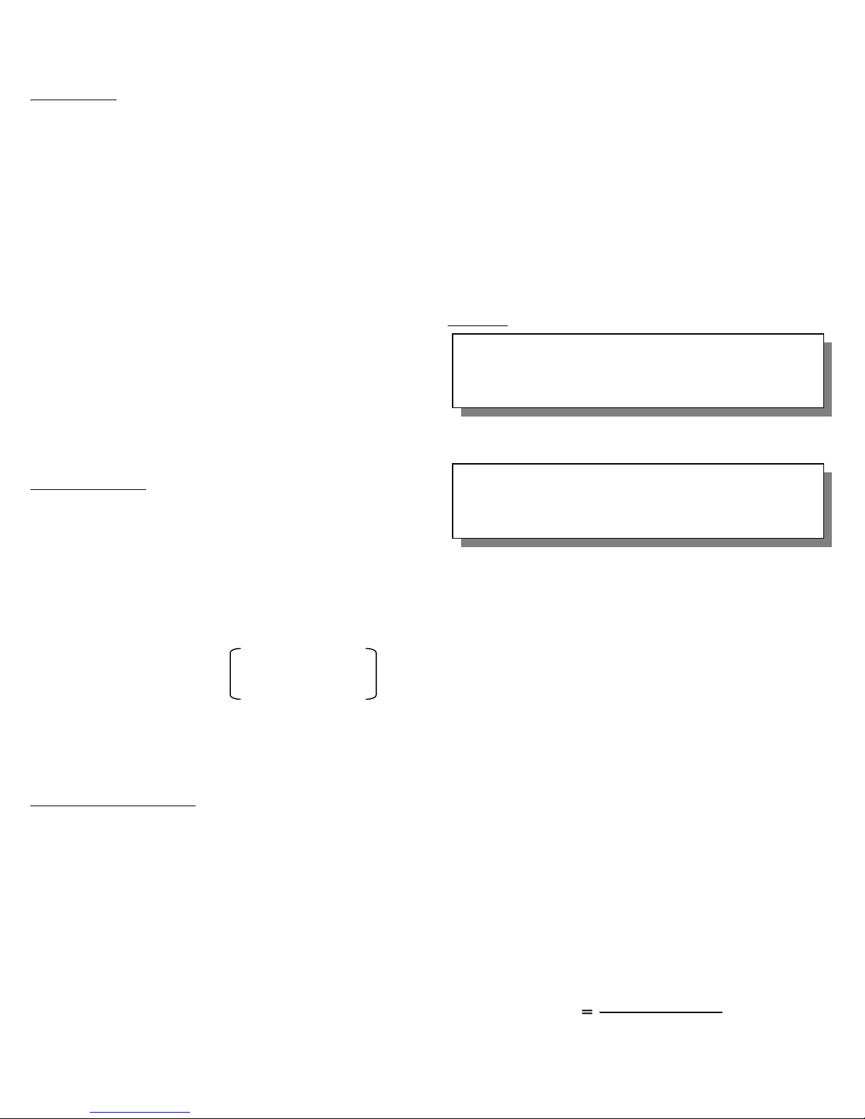
Thermal expansion of the heater pipes must be considered
when locating the heater. It can be approximated as:
If the heater is installed in a pressurized tank, a relief valve
must be installed. As a minimum, the valve must be sized to
relieve at a rate equal to the rate that the heater can thermally
expand fluid in the tank.
Pipe Assembly Installation
On assemblies provided with ANSI flanged connections, take
care to prevent scratching the flange faces. INDEECO
supplies a non-asbestos nitrile bonded fiber flange gasket
unless otherwise requested. The user must confirm that the
gasket is suitable for the application. The user must supply
high strength studs or bolts and nuts, such as A-193 GR. B7
and A194 GR. 2H, rated for the design conditions. Bolts must
be properly installed and tightened to prevent leaks.
When an adapter box is provided, the assembly is welded
directly to the user’s tank wall. A rectangular cutout is
required; not to exceed the adapter box dimensions plus ¼”.
Pipe
Length
(Inches)
x .00001 x
Max Pipe
Operating
Temp (°F)
- 70°F
Heater pipes must be supported inside the user’s tank.
Supports must not prevent the pipes from thermally
expanding. Supports should be located on a maximum
spacing of 10 feet.
Where buildup of solids in the bottom of the tank is expected,
the pipes must be located above that level. The pipes must
also be located below the minimum operating fluid level of the
tank.
Heater pipes must be perfectly clean before installation of
heating element. Use only a clean dry cloth to clean. Never
use a lubricant. Compressed air with a long wand may be
used to remove ceramic chips, etc.
Insulation
Surfaces of the heater pipes extending beyond the
user’s vessel may be extremely hot. Avoid contact to
revent personnel injury or fire.
WARNING
The customer may prefer to insulate the flange or adapter
box at the tank for personnel safety and energy conservation.
Do not insulate the terminal enclosure or the first 2” of
the pipe. Dangerous over-heating of the terminal box
wirin
could result.
WARNING
The heating elements are provided with a “cold section”
where stainless steel bussing is used to connect to the
heating coils. This area must be packed with insulation to
prevent over-temperature of the terminal enclosure.
Insulation was factory installed before shipment.
Electrical Instructions
The potentially high operating and ambient temperatures of
Storage Tank Heaters require field wiring to the heater be
carefully matched to the application, to avoid serious injury or
damage to the equipment. The wiring must be de-rated for
the expected terminal box temperature. Terminal box
temperatures are typically below 120
can be expected for heaters used in cold climates for freeze
protection. If the cold section of the heater is properly
insulated, 90
o
C minimum wire may typically be used. Refer
to the National Electrical Code.
The size and type of incoming field wiring will depend upon
the heater terminal box temperature, heater current draw per
conductor, number of conductors per conduit, and wire
insulation rating. Field supplied conductors must be sized for
at least 125% of the circuit current.
To calculate the circuit current (in amps):
KW x 1000 Single phase
Line current Line Voltage
2
o
F. Lower temperatures
Page 3

Line current Line current 1.732 x Line Voltage 1.732 x Line Voltage
For wiring recommendations refer to the wiring diagram. An
For wiring recommendations refer to the wiring diagram. An
additional copy is provided inside the heater terminal box.
additional copy is provided inside the heater terminal box.
Wiring to the heater should be permanently installed in
Wiring to the heater should be permanently installed in
metallic or non-metallic electrical grade conduit in accordance
metallic or non-metallic electrical grade conduit in accordance
with all applicable electrical codes, and should include a
with all applicable electrical codes, and should include a
grounding conductor if non-metallic conduit is used.
grounding conductor if non-metallic conduit is used.
Field supply wiring must be rated for 600Vac. Use copper
Field supply wiring must be rated for 600Vac. Use copper
conductors.
conductors.
The electrical installation should include a service disconnect
The electrical installation should include a service disconnect
switch in sight of the heater, as well as branch circuit over-
switch in sight of the heater, as well as branch circuit overcurrent protection and over-temperature protection, if not
current protection and over-temperature protection, if not
provided with the heater.
provided with the heater.
Where thermocouple extension wire is required between the
Where thermocouple extension wire is required between the
heater and remote controls, verify it is connected with proper
heater and remote controls, verify it is connected with proper
polarity, as shown on the wiring diagram. Failure to do so
polarity, as shown on the wiring diagram. Failure to do so
may result in an uncontrolled heater. Refer to the wiring
may result in an uncontrolled heater. Refer to the wiring
diagram for the required wire type. Shielded wire is
diagram for the required wire type. Shielded wire is
recommended to reduce signal interference.
recommended to reduce signal interference.
OPERATION OPERATION
Cautions and SetupCautions and Setup
Equipment should be operated by qualified personnel
only to prevent equipment damage or failure.
DO NOT TURN ON HEATING ELEMENTS UNTIL
TANK IS COMPLETELY FULL OF FLUID.
Permanent damage may result if elements are
energized and the heater is not completely
submerged.
Carefully review all instructions and become familiar with the
equipment, safety interlocks, and process temperature
controller provided before energizing the equipment.
DO NOT operate heaters at voltages in excess of that
marked on the heater. Excess voltage can shorten heater life
or overload the branch circuit wiring.
DO NOT operate heaters unless properly filled with liquid.
DO NOT leave heating systems operating unattended unless
a closed-loop process controller and over-temperature safety
equipment have been completely validated.
DO NOT operate heaters at pipe temperatures higher than
the recommended maximum. Excess temperatures can
cause premature failure. Generally, pipe materials are limited
to the following maximum temperatures.
CAUTION
WARNING
KW x 1000 KW x 1000 Three phase Three phase
Retighten all electrical connections that may have
loosened during shipment. Failure to do so may result
in damage to the heater or risk of fire.
Confirm all unused conduit holes in the terminal box are
Confirm all unused conduit holes in the terminal box are
sealed with plugs suitable for the heater environment.
sealed with plugs suitable for the heater environment.
Attach a ground conductor to the mounting screw for the
Attach a ground conductor to the mounting screw for the
heater in the terminal box, or by other appropriate means, per
heater in the terminal box, or by other appropriate means, per
NEC Article 250.
NEC Article 250.
Be sure the terminal box cover is properly installed at all
Be sure the terminal box cover is properly installed at all
times to ensure personnel protection. Also, contaminants can
times to ensure personnel protection. Also, contaminants can
create leakage, (shock) hazards, permanent heater damage
create leakage, (shock) hazards, permanent heater damage
or failure and should be avoided.
or failure and should be avoided.
It is recommended to perform an insulation resistance test
It is recommended to perform an insulation resistance test
prior to energizing the equipment. If the value is less than 1
prior to energizing the equipment. If the value is less than 1
Meg Ohm using a 500Vdc or similar tester, refer to
Meg Ohm using a 500Vdc or similar tester, refer to
Maintenance and Troubleshooting sections.
Maintenance and Troubleshooting sections.
Pipe
Material
Steel
Stainless Steel 304
Ensure power ahead of the panel is off and perform the
following steps:
1. Exercise all switches, circuit breakers and operating
mechanisms to confirm they operate freely.
2. Conduct an insulation resistance to ensure the system is
free from short circuits or grounds.
INDEECO recommends that all safety interlocks be tested
during initial startup to ensure they properly disable the
heater. After 10 days of operation, retighten all electrical
connections.
For solid state non-indicating controllers, it is recommended
to dial the high limit controller set-point down to a point below
normal operating temperature, either during initial startup
operation or with only the control circuit on, and verify that the
contactors open, disconnecting heater power. Return the
controller to the desired setpoint.
PID controlled systems must be auto-tuned after initial
installation to optimize control accuracy.
Refer to information noted below on Control Methods.
During initial heating, it is recommended to slowly ramp up
the process setpoint and inspect the heating system for
problems such as excess pressure buildup, or binding of
equipment due to thermal expansion.
WARNING
Maximum
Pipe Temperature
750° F
1400° F
3
Page 4

Initial Operation
Turn the Control Circuit Switch to the OFF position.
Turn on power ahead of the panel and close main disconnect
switch.
If a digital indicating process controller is included with the
panel, place the controller in the “Standby” mode and adjust
the process setpoint to ambient. Refer to manufacturer’s
instructions for controller setup. When process control is
from a remote DCS system or controller, disable the
controller output signal or reduce the setpoint to ambient.
Review the setup of the process controller. INDEECO
factory-configures the controller inputs and outputs unless a
special controller is specified by the user.
Place the process controller in the “Standby” mode any time
that the control circuit switch will be in the OFF position
longer than a few seconds. This is important to prevent the
process controller from driving to 100% output when the
control circuit switch is returned to the ON position.
Turn the Control Circuit Switch to the ON position.
Inspect for alarm pilot lights. Push any red illuminated reset
pilot lights to attempt resetting. All alarm lights should be
reset.
Remove the controller from the Standby Mode.
Increase the process setpoint 10 or 20 degrees and confirm
operation without alarms.
Once all alarm conditions are cleared, follow instructions in
process controller manual for auto-tuning (not applicable for
CONTROL METHODS
Heater Control Methods
Many factors affect the setpoint tolerance and control of
heating systems. Control method, heat load fluctuations,
sensor location, controller tuning, and fluid thermal properties
are significant factors that impact process control.
Control methods for electric heaters can either be:
1. ON / OFF
2. Proportional, Integral, and Derivative (PID).
ON/OFF Systems
On/off systems utilize a process similar to a thermostat that
operates a home furnace. A typical heater control circuit is
provided with digital indicating process controller which
accepts a thermocouple input from the process. The
controller is configured to a SSR output to pull power
contactors in and out to cycle the load.
ON-OFF control), and refer to information noted below on
Heater Control Methods for tuning.
Note that auto-tuning must be initiated while the temperature
of the process fluid is below the normal operating
temperature.
Gradually increase the control setpoint and observe the
system for proper operation.
Adjust high limit temperature controllers by setting as close to
the operating conditions as possible without nuisance
tripping.
After any alarm condition, the system should be investigated
and the problem remedied. Do not operate the equipment
with safety devices disabled or serious damage to the system
may result.
On flange mounted heaters, re-tighten flange bolts after the
heater has completed one or two heating cycles.
Shut Down
The heating system may be shut down by reducing the
process setpoint to ambient.
Turn the control circuit switch to OFF. Turn off main power
disconnect switch.
Normal Operation
Turn on disconnect switch.
Adjust process controller to the desired setpoint.
Turn control circuit switch to ON.
Note: be sure to use the Standby mode if the above steps
can not be accomplished quickly.
The process controller must be configured to limit the cycle
rate to avoid quickly wearing out the power contactors.
Contactors are typically rated for 100,000 cycles of operation.
Two methods can be used: “Hysteresis” or “Cycle Time”.
Hysteresis defines a temperature range around the setpoint
where the process controller will not change the state of the
power contactor. A hysteresis value of 5
o
F would define the
“error” or tolerance from setpoint that the user can accept.
This is sometimes referred to as deadband.
Cycle Time is a method to define the minimum time that the
controller must wait between de-energizing and re-energizing
the power contactor. A Cycle Time of 3-5 minutes on
equipment operating continuously would wear out power
contactors in about 2 years. If the Cycle Time is set for 3
minutes, but the temperature has not yet dropped below the
setpoint, the heater will not come on until the temperature
drops low enough.
4
Page 5

PID Control
PID control utilizes Proportional, Integral, and Derivative
control methods to scale the output from a process controller
(typically 4-20mA) to an SCR Power Controller or Electronic
Multi-Stage Sequencer. Note that reverse acting signals are
used with heating systems where the heater is OFF at 4mA
and fully on at 20mA.
SCR Power Controllers employ heavy duty SCR switching
modules to switch the power. The SCR uses a fixed time
base of typically 4 seconds. Within every 4 second time
base, the SCR closes to energize the heater for a time frame
proportional to the control signal. A 50% signal, or 12mA,
would mean the heater is on for 2 and off for 2 seconds every
4 seconds. The result of cycling the heater frequently, but
proportional with the load requirement, is more accurate
temperature control.
An Electronic Multi-Stage Sequencer, or Step Controller,
accepts the scaled control signal output from a PID Controller
and pulls contactors in and out as required. This method is
similar to ON/OFF control with multiple stages. The
sequencer has an adjustable Cycle Time similar to that used
for ON/OFF process controllers. The default used on
sequencers is a 40 second delay between stages. This
method is effective on high amperage units because the
multiple stages help split the load into manageable circuits.
For further details about PID control, refer to the process
controller instruction manual.
Factors Impacting System Control
Many factors affect the setpoint tolerance and control of
heating systems. Control Method (noted above), Heat Load
Fluctuations, Sensor Location & Thermal Lag, Controller
Tuning, and Fluid Properties are all significant factors.
Heat Load Fluctuation, or changes in the process, can
cause wide temperature fluctuations. Some typical changes
to a heating process loop are:
1. Addition of fluid at a temperature below the process
temperature.
2. Opening or closing tank access covers.
3. Starting or stopping fluid agitators.
4. Ambient temperature changes.
5. Fluid flow rate changes.
6. Insulation thickness.
7. Power available can be affected due to user voltage
fluctuations.
Process Sensor Location / Lag in the tank or piping can
impact temperature control. For flowing systems, the sensor
must be in the flow stream down-stream from the heater. For
stagnant systems, If the sensor is located close to or on the
heater, the controls may short-cycle before the tank is up to
temperature. Locating the sensor away from the heater will
cause a temperature lag and allow fluid temperatures close to
the heater to exceed desired temperatures. Thermal Lag is a
term relating to process control. Lag is typically a slow
reaction by the process sensor to a change in the operating
temperature. This is often caused by thermowells. The mass
of the thermowell requires heat-up time or “time lag” before
the sensor can detect that the operating temperature has
reached the setpoint, thus causing overshoot of the setpoint.
The PID controller must be tuned down to minimize this
impact, which has the result of less accurate temperature
control.
Controller Tuning is necessary on systems with SCR’s or
Sequencers and PID control. Tuning allows the proportional,
integral, and derivative values to be set based on the actual
process conditions. Process controllers are provided with an
auto-tuning feature that measures the thermal
responsiveness of the heating system. During auto-tuning,
the process controller drives the system to heat up, hold, heat
up, and finally, hold. If an alarm condition is encountered
during auto-tuning such as a high limit alarm, the cause of the
alarm must be remedied and the auto-tune must be repeated.
Tuning may need to be repeated after any change in the
process which affects the thermal responsiveness of the
system such as the heat load, flow rate, or fluid properties.
Systems which are unsteady may require manual tuning.
Refer to the process controller manual for instructions.
Fluid Thermal Properties can greatly impact temperature
control. Fluids such as water, with high thermal conductivity,
are easy to heat without experiencing large temperature
gradients. Fluids such as wax or tar pitch have such low
thermal conductivity that heaters must be designed with a
much lower sheath watt density than with most fluids.
Temperature gradients can be significantly reduced in tanks
by using an agitator. Solids buildup on the heaters can also
reduce the heat transfer.
To obtain optimum control, the use of PID control, properly
tuned for the application, is recommended.
5
Page 6

MAINTENANCE
Troubleshooting and repairs should only be attempted
by qualified maintenance personnel.
Hazardous voltages are present in this equipment.
Lock out and tag the branch circuit disconnect switch
before working on this heater.
Periodically check all electrical connections, including field
and factory-made connections for tightness, and all wiring for
deterioration at least once a year.
Periodically inspect for leakage and retighten flange bolts
when required.
Inspect the terminal enclosure and conduit connections for
evidence of water leaks or moisture collection. Tighten
connections as required. Do not continue using a heater with
signs of damage.
Heating Element Installation & Removal
Remove electrical terminal connections after noting how they
are connected. Remove insulation blanket in the bottom
section of the terminal box to provide access to the heating
elements.
To remove the heating element from a heater pipe, first
remove the fastening nut at the terminal end. Hold the
ceramic insulator firmly in order to avoid undue pressure on
the ceramic and possible breakage. If obstructions are
encountered, rotate the heater slightly back and forth while
pulling out.
Since heating elements can be of considerable length, it may
not always be possible to remove the element in a straight
line, due to space limitations. Since the element bar is
flexible, the element may be curved on a radius of 4 feet
minimum. It is recommended that at least 2 people be used
for this procedure, in order to avoid breaking the ceramics.
After the element bar has been removed, it should be
carefully stretched out on a clean table for inspection. Broken
ceramics must be replaced and burn spots should be cleaned
with a dry clean paper or cloth towel. Oil or other
contamination on the heater will cause a failure.
When installing the heating element into the heater pipe,
reverse the steps noted above.
Heater pipes must be perfectly clean before installation of
element. Use only a clean dry cloth to clean. Never use a
CAUTION
WARNING
lubricant. Compressed air with a long wand may be used to
remove ceramic chips, etc.
CAUTION -Hazard of Electric Shock
Heaters must be bolted into position at the terminal
end to prevent movement, which could allow the
heater to short out against the pipe.
See figures attached for mounting configurations.
The heating element is only intended to be installed with the
sheet metal strip on the bottom. Do not rotate the heater in
the pipe.
Thermal insulation must be installed between the first few
ceramics in the “cold” section of the heater where the
resistance wire is not coiled. A loose fill cerafiber (INDEECO
P/N 1008466) or equal, rated for 2000°F, is preferred. The
insulation must be free of moisture or contamination in order
to provide electrical isolation. The insulation is necessary to
allow 90°C rated field wiring.
Caution, INDEECO recommends replacing the entire pipe
insert assembly under most conditions. The condition of the
ceramics must be considered before attempting to replace
coils. Field replaced heating coils must be installed properly
or failure may occur.
If field-replacing one or more heating coils, mechanical
connections at the end ceramics need to be removed.
Remove the burned out coil from both ends by pulling lightly,
and at the same time turning the coil back and forth. Check
the ceramics near the area where the burnout occurred.
Broken ceramics must be replaced, and burn spots should be
cleaned with a dry clean paper or cloth towel. Oil or other
contamination on the heater will cause a failure.
The new coil should be stretched to the correct length (do not
over stretch), and then inserted from the far end by lightly
pushing with a constant back and forth turning motion. After
the coil is in place, the loop at the end of the coil should be
guided over the bolt on the end ceramic and then tightened in
place with the previously removed unit.
Re-install the heating element in the pipe by reversing the
instructions above.
Use care when making connections to the heating element to
avoid breaking the end ceramic.
Where the heater is installed in cold climates, consider safety
precautions to prevent damage due to freezing fluid when the
heater is not in service.
6
Page 7

Troubleshooting and repair should only be
attempted by qualified maintenance personnel.
CAUTION
The nature of the ceramic insulators used to electrically
isolate and support the nickel chromium resistance wire in
the heating elements is such that over a long period of
storage, they will absorb considerable moisture from the
atmosphere unless the pipe and conduits are sealed. It is
recommended to perform an insulation resistance test prior
to energizing the equipment. If the value is less than 1 Meg
Ohm using a 500Vdc or similar tester, care must be taken to
dry out the heater to prevent failure. It is recommended that
the elements be turned on at a reduced voltage at first, to
boil off the moisture. Meg Ohm readings may drop initially
HAZARDOUS AREAS
TROUBLESHOOTING
INDEECO strongly recommends installation be performed
by qualified personnel familiar with the National Electrical
Code and all local codes and standards regarding
explosion-proof equipment. It is the responsibility of the
installer to verify the safety and suitability of the
installation.
WARNING – Explosion Hazard
Per article 500-516 of the National Electrical Code, a
hazardous area is defined by a “Class”, “Division”, “Group”,
and “Temperature Code”. The Class can be I or II, where
Class I indicates that the hazard classification is due to the
presence of an explosive vapor. Class II indicates an
explosive dust. The division can be either 1 or 2. Division 1
indicates a hazard is ALWAYS considered to be present.
Division 2 means the hazard is only present under abnormal
conditions. The Group defines the explosiveness of the
hazard. The Temperature Code specifies the temperature at
which a hazard will ignite.
INDEECO can provide designs suitable for all of the above
conditions, but a heater should never be placed in an
environment not noted on the heater nameplate.
NEVER operate the heater in an atmosphere with an ignition
code temperature LOWER THAN the nameplate rating. The
user must determine the actual area classification.
Special design considerations for electric heaters used in
hazardous locations:
1. Locate all electrical connections in an appropriate
enclosure.
2. Prevent surface temperatures of the heater from
exceeding the design ignition temperature.
INDEECO Storage Tank Heaters designed for hazardous
locations are typically provided with a purged terminal
enclosure.
(where applicable)
after a few minutes of operation, indicating moisture being
forced out of the elements. The terminal enclosure lid
should be left open during this period to allow the moisture
to escape.
If the heater has a manual-reset high limit thermostat, be
sure that the reset button is pressed in.
If reduced heat output is suspected, verify the condition of
the heating elements by using an ammeter to check the
current draw of each input line. All input lines should draw
approximately equal current, which should agree with
nameplate rating. If they do not, one or more of the heating
elements could be damaged.
When the design temperature of the process exceeds the
rated ignition temperature, it is critical that the heater and all
customer piping is properly insulated.
A hazardous area heater must be powered and controlled by
a heater control panel designed to provide necessary overtemperature safety interlocks. Contact INDEECO if
assistance is required to properly control and protect the
heater.
Never apply power to a heater in a hazardous atmosphere
unless all terminal box covers are properly installed with all
cover bolts.
All conduits entering the heater terminal box must be sealed
within 18” of the heater using an explosion-proof conduit seal.
Any unused openings must be properly sealed with a steel
pipe plug. Follow the NEC for specific conduit requirements
such as the requirement for Rigid Conduit.
To ensure proper flamepath, all threaded conduits must use
rated fittings and be tight, with a minimum of 5 good threads
engaged. Any machined metal-to-metal surfaces on terminal
boxes must be handled carefully to prevent scratches which
may void the explosion-proof rating.
Operating the heater at a voltage higher than the
nameplate value may result in elevated
temperatures and amperage above the design
ratings.
Proper grounding of equipment in hazardous areas is critical
to eliminate potential sources of sparking.
Replacement of electrical components should only be done
by authorized personnel familiar with the requirements of
maintaining electrical equipment in an explosion-hazard area.
7
WARNING - Risk of Explosion
Page 8
INDEECO
425 Hanley Industrial Court
St. Louis, MO 63144
Phone: (314) 644-4300 Fax: (314) 644-5332
www.indeeco.com
78-2200-83-1
8
 Loading...