

Page 1
INCRA Wonder Fence Addendum
Attaching the Wonder Fence and Hi-Rise
Accessories to the Ultra with the Pro II Fence
You have purchased the Incra Jig Ultra equipped
with the new Pro II Fence. Use the following
instructions for attaching the Wonder Fence and HiRise Fence cap braces. These instructions will be
used in place of the referenced instructions from the
Wonder Fence owner’s manual.
ATTACHING TO YOUR INCRA JIG ULTRA
(Replaces “Attaching to your Incra Jig Ultra” from
page 3 of the Wonder Fence owner’s manual.)
Loosen attachment fasteners
Insert the supplied hex tool through the two large diameter access
holes located on the front of each Wonder Fence and loosen the
two socket head screws. Do not remove the rectangular nuts.
For a better view of the fasteners, loosen the thumbscrew and slide
the black plastic view panel located on the top of each fence half.
See Fig. 1.
FIG. 1
Use hex tool to loosen fasteners
thru the two larger holes
Slide Wonder fence into position on Pro II fence
Slide the two rectangular nuts on each Wonder Fence into the T-slot
located on the front face of the Pro II Fence. Position the Wonder
Fence halves so that your router collet is centered on the opening
between the fences, then tighten the two socket head screws on
each fence half. Slide the view panel back in place and tighten the
thumbscrew. See Fig. 2.
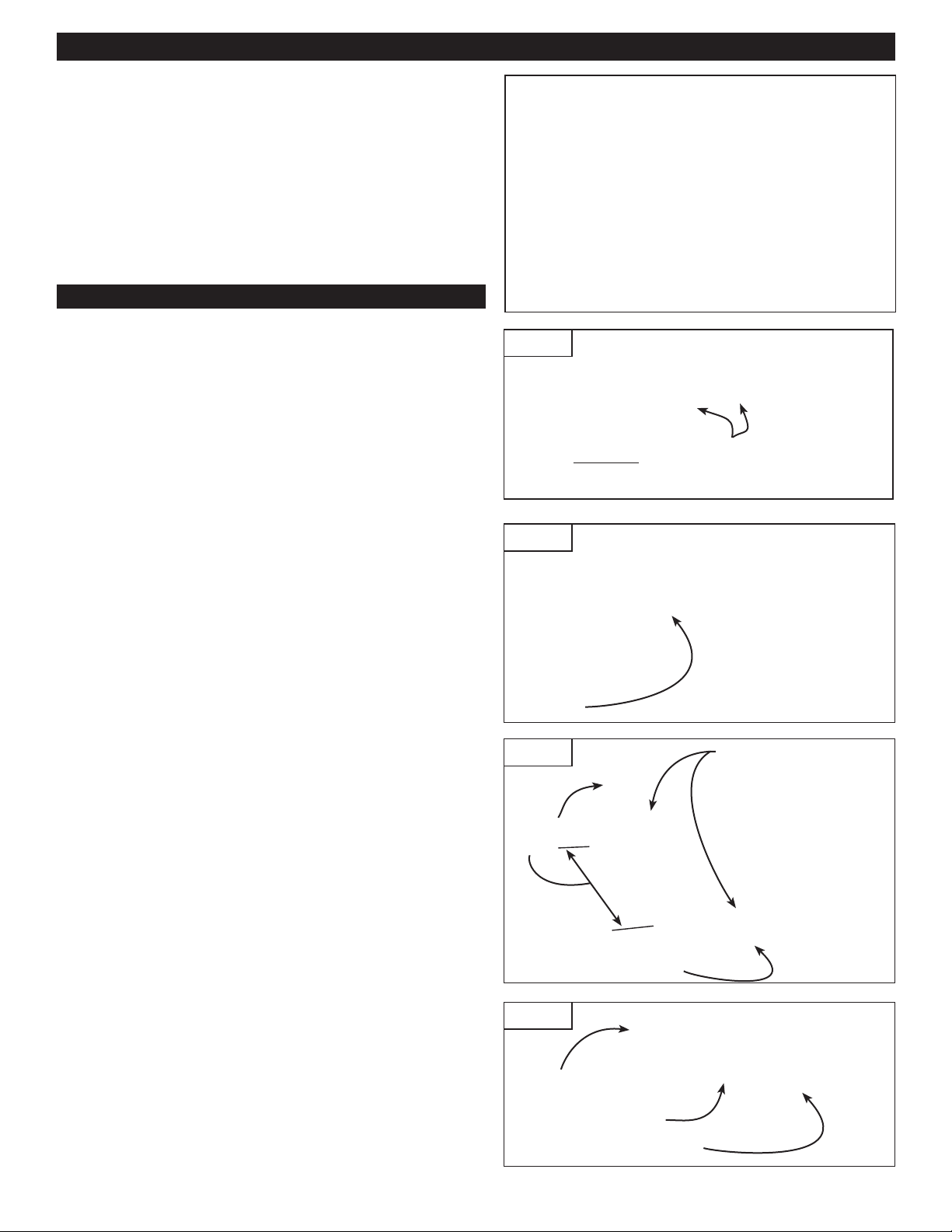
Attach fence cap braces and support brackets
(Replaces Step 1, from page 10 of the Wonder Fence
owner's manual.)
1
Place a
/4" washer on each of the (2) 1/4-20 x 5/8" socket head
screws and insert through the hole on the front of each fence
brace. Loosely thread on a
1
/4-20 rectangular nut then slide the
nut into the T-slot located on the top of the Pro II fence. See Fig.
3. Locate the two braces on the fence spaced 75/8" apart. Tighten
the fasteners with the supplied hex tool.
FIG. 2
Slide nuts
into T-slot
FIG. 3
Fence
cap
brace
7 5/8"
Rectangular nuts captured
in T-slot
1
/4-20 x 5/8" socket head
screws with washers
Place a
screws supplied and insert through the slotted holes located on the
support brackets. Loosely thread on a
slide the nut into the T-slot located on the rear of the Pro II Fence.
Position the support brackets directly under the fence cap braces.
Slide the support brackets up to firmly contact the underside of the
fence cap braces then tighten the socket head screws. See Fig 4.
You can now continue the Hi-Rise Fence Cap assembly beginning
with Step 2 from page 10 of the Wonder Fence owner's manual.
1
/4" washer on each of the (2) 1/4-20 x 1/2" socket head
1
/4-20 rectangular nut then
FIG. 4
Fence
cap brace
1
/4-20 x 1/2 socket
head screw with washer
Support bracket rectangular
nut captured in T-slot
Manufactured by: Taylor Design Group, Inc. ■ P.O. Box 810262 ■ Dallas, Texas 75381 02-2005
 Loading...