

Page 1
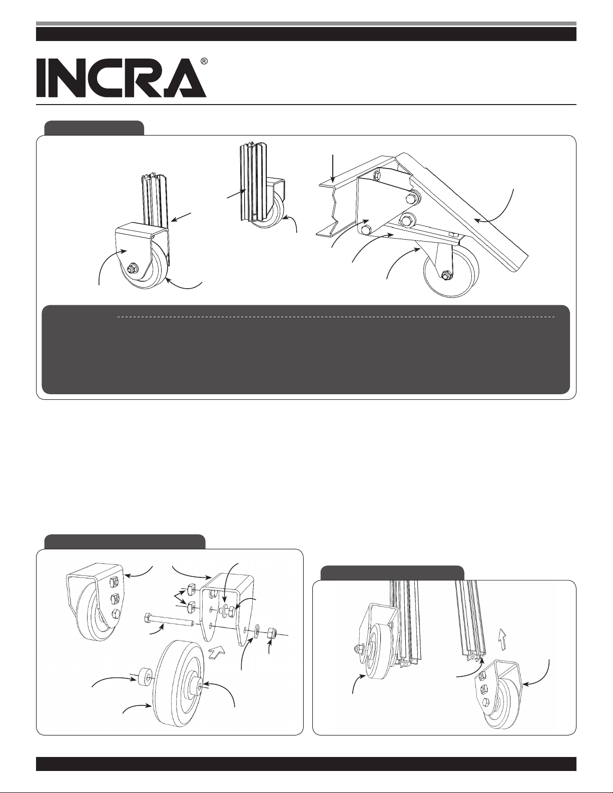
Fig. 1 Wheel Kit
Table Stand Legs
Leg Wheel (2)
Leg Wheel Bracket (2)
Parts List:
(1) Front Wheel Connector Bracket
(1) Front Wheel Pedestal
(1) Front Wheel Foot Pedal
(1) Front Wheel Caster
(2) Leg Wheel Bracket
(2) Leg Wheel
Wheel Stringer on Table Stand
Leg Wheel (2)
Front Wheel Connector Bracket
Front Wheel Pedestal
1
(8)
/4-20 x 1/2 Hex Bolt
1
(2)
/4-20 x 2 1/4 Hex Bolt
5
(6)
/16-18 x 1/2 Hex Bolt
5
(2)
/16-18 x 3 3/4 Hex Bolt
1
(8)
/4-20 Square Nut
1
(2)
/4-20 Locking Nut
INCRA Wheel Kit
Assembly Instructions
Front Wheel Foot Pedal
Front Wheel Caster
5
(6)
/16-18 Hex Nut
5
(2)
/16-18 Locking Nut
1
(11)
/4” Flat Washer
1
(4)
/4” Lock Washer
1
(4)
/4 id x 1/4 Thick Nylon Washer
5
(4)
/16 id x 3/16 Thick Nylon Washer
Step 1. Assemble Leg Wheels.
First, loosley install two sets of
nuts and
1
/4” washers in each wheel bracket as shown in Fig. 2.
1
/4-20 x 1/2 bolts, 1/4-20 square
Second, install a rubber wheel in the lower hole on each wheel
bracket using the
steel washer and
Be sure that the two
1
/4-20 x 2 1/4 hex bolt, 1/4-20 locking nut, 1/4”
1
/4” thick Nylon washers as shown in Fig. 2.
1
/4” thick Nylon washers are against the hub
of the wheel and positioned INSIDE the wheel bracket. Install,
but do not fully tighten the locking nut on the 2
1
/4 hex bolts
at this time.
Fig. 2 Assemble Leg Wheels
1
1
/4“ Thick Nylon Washer
Wheel
Leg Wheel Bracket
1
/4-20
Square Nut
/4-20 x 21/4
Hex Bolt
1
/4“ Thick Nylon Washer
1
/4“ Washer (4)
1
/4“ Washer
1
/4-20 x 1/2
Hex Bolt (4)
1
/4-20
Locking Nut
Step 2. Install Leg Wheels on Legs.
Orientation: When mounting the stand to offset tables, the two
leg wheels should be located under the end of the table WITH
the router cutout in it. For center mount router tables, the two
leg wheels can be on either end of the table.
Remove the levelers from the two legs on which the wheels will
be installed. As shown in Fig. 3, slide the (2) square nuts and
the long hex bolt head on each wheel assembly into the T-slot
on the leg extrusion. Adjust the vertical position of each wheel
for stability, then firmly tighten all bolts. Tighten the locking nut
enough to remove all side play between the wheel and the
inside of the wheel bracket, but still loose enough for the wheel
to pivot freely.
Fig. 3 Install Leg Wheels
Infeed Wheel
Assembly
Capture Square
Nuts & Hex Bolt
Outfeed Wheel
Assembly
in T-Slot on Leg
w w w. i n cr a .c o m
1Assembly Instructions for the INCRA Wheel Kit
Page 2
INCRA Wheel Kit Assembly Instructions
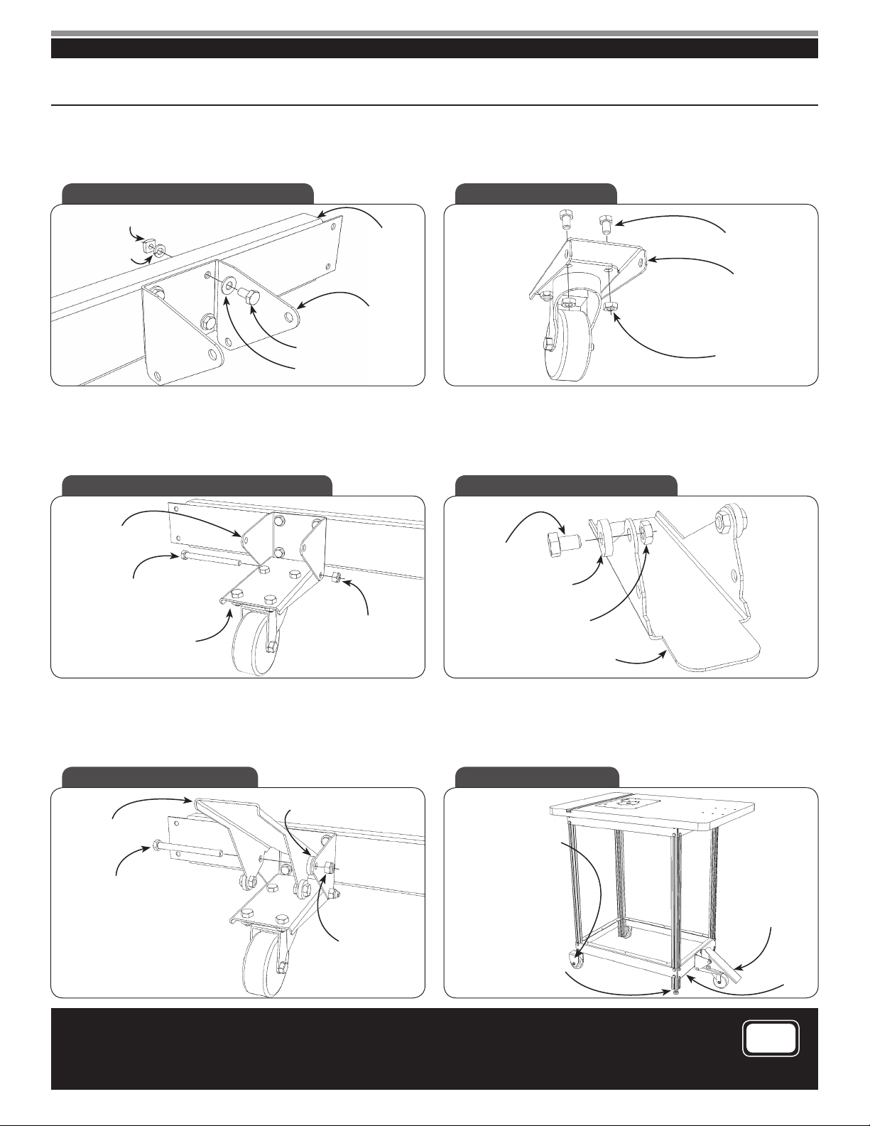
Step 3. Install connector bracket on wheel stringer.
Orient the front wheel connector bracket as shown in Fig. 4,
then attach it to the wheel stringer using
1
/4” washers, 1/4” lock washers and 1/4-20 square nuts.
1
/4-20 x 1/2 hex bolts,
Step 4. Install caster on front wheel pedestal.
5
Using
/16-18 hex bolts and 5/16-18 hex nuts, attach the swivel
caster to the underside of the front wheel pedestal as shown in
Fig. 5.
Fig. 4 Install Connector Bracket Fig. 5 Install Caster
1
/4-20 Square Nut
Wheel Stringer
1
/4” Lock Washer
Front Wheel
Connector Bracket
1
/4-20 x 1/2 Hex Bolt
1
/4” Washer
Step 5. Attach assembled front wheel pedestal to connector bracket.
Attach the assembled front wheel pedestal to the lower holes in
the connector bracket by using a
5
/16-18 locking nut, Fig. 6. The front wheel pedestal must pivot
5
/16-18 x 3 3/4 hex bolt and
Step 6. Install NYLON washers on foot pedal.
Attach two of the
the foot pedal using
3
/16” thick NYLON washers to the outside of
5
/16-18 x 1/2 hex bolts and 5/16-18 hex nuts
through the holes indicated in Fig. 7. Tighten securely.
freely. Do not overtighten.
Fig. 6 Install Front Wheel Pedestal Fig. 7 Install Nylon Washers
Front Wheel
Connector Bracket
5
/16-18 x 3 3/4 Hex Bolt
Assembled Front
Wheel Pedestal
5
/16-18 Locking Nut
5
/16-18 x 1/2
Hex Bolt
3
/16“ Thick Nylon
Washer
5
/16-18 Hex Nut
Foot Pedal
5
/16-18 x 1/2 Hex Bolt
Front Wheel Pedestal
5
/16-18 Hex Nut
Step 7. Attach foot pedal to connector bracket.
Attach foot pedal to the upper holes in the connector bracket
by using a
3
/16” thick Nylon washers, Fig. 8. The foot pedal must pivot
5
/16-18 x 3 3/4 hex bolt, 5/16-18 locking nut and two
Step 8. Operation and adjustments.
Engage the swivel caster by pushing down on the front end of
the foot pedal with your foot. Disengage the caster by pushing
down on the other end of the foot pedal with your foot, Fig. 9.
freely. Do not overtighten.
Fig. 8 Install Foot Pedal Fig. 9 Adjustments
3
/16“ Thick Nylon Washer
Note: TWO washers. One on
Foot Pedal
5
/16-18 x 3 3/4 Hex Bolt
Manufactured by:
Taylor Design Group, Inc.
P.O. BOX 810262 Dal la s, TX 75381
www .i n cra .c om
each side of foot pedal.
Adjust Vertical Position
of Leg Wheels for
Stability
Adjust the height of the
wheel stringer and the
leg levelers on either
side of the swivel caster
so that the leveler pads
5
/16-18 Locking Nut
INCRA is a Registered Trademark of Taylor Design Group
©2007 Taylor Desig n Group, Inc.
INCR A Tools a re pro tected by one o r more o f the fo llow ing US p aten ts:
#4, 793, 604 , #4 ,930 ,2 21, #5,195, 730 , #5, 275, 074, # 5,4 23, 360, #5,7 16,045, # 6,2 37,457,
#6,5 57,601, # 6,672,190. Oth er patent s granted o r pend ing. rev.02. 25.08
are OFF the oor when
the foot pedal is en-
gaged, and on the oor
when the foot pedal is
disengaged.
Push foot pedal
down here with your
foot to engage the
swivel caster.
Push other end to
disengaged.
Wheel
Stringer
MADE IN THE
USA
2
 Loading...