

Page 1

ww w.incra.com
www.incra.com
Instructions
Saf ety
• Before using the INCRA Miter V27, read and follow all of the instructions
and safety information in this document.
• When using the INCRA Miter V27 in conjunction with any other tool,
rst read and follow all instructions and safety information in that
tool’s owner’s manual.
• When using the INCRA Miter V27, always keep your hands clear of the
cutter and the line of cut.
• Always turn off the power and make sure that the cutter comes to a
complete stop before changing the setting of any part of the INCRA
Miter V27.
• Always securely tighten the large black clamping knob before starting
any cut.
• Wear safety glasses, hearing protection, and follow all normal shop
safety practices.
• After making any adjustments to the miter angle of your INCRA Miter V27,
always verify safe clearance between the cutter and protractor before
turning on the power.
Setu p
Adjust the Miter Bar for a Perfect Fit in Your Miter Channel
1
Place the V27 in your tool’s
Miter Channel. NOTE: If the
miter channel does not have
a T-slot, remove and save the
Retaining T-clip and screw located at the end of the miter
bar as shown in Figure 1.
2
Using the supplied 3/32” hex key, adjust each of the (3) visible miter bar
expansion disks for a zero-side play, sliding t in your miter channel as shown
in Figure 2. Turning the fastener clockwise EXPANDS the bar width. The disks
are designed to require a fair amount of adjustment torque for proper expansion.
Fig. 2
Miter Bar
Expansion
Disks for Miter
Bar
3/32” Hex Key
Fig. 1
Retaining
T-cl ip
Visit our website at www.incra.com for miter accessories along with
many other exciting and practical incremental woodworking tools.
MADE IN THE
USA
INCR A - MAKING ACCURACY EASY!
Manufactured by:
Taylor Design Group P.O.BOX 810262 Dallas, TX 75381
P: 972-242-9975 F: 972-242-9985
INCR A is a Regi stere d Tradem ark of Ta ylor Design G roup, Inc.
©2016 Tay lor De sign Group, Inc. Rev.06/16
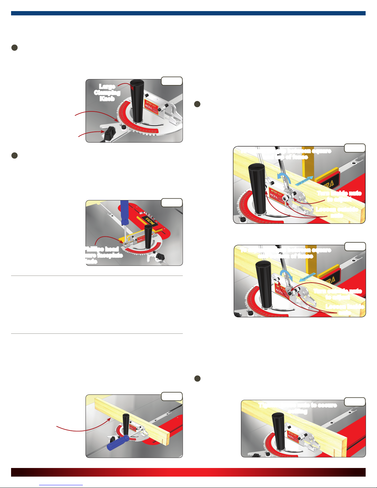
3
Remove the large clamping knob and disengage the indexing tooth from
the protractor. Pivot the protractor head to access and adjust the fourth expansion point. See Figure 3. Replace the large clamping knob.
Large Clamping
Knob
Indexing
Toot h
Protractor
Head
Adjust Final Disk
Fig. 3
Page 2
Square Miter Faceplate to your Application
(table saw, router table, etc.)
1
Caution: Always unplug the power tool before squaring the faceplate to your application. Loosen both the large and the small clamp-
ing knobs. Set the indexing tooth to 0 degrees, and tighten the small
clamping knob, then tighten the large clamping knob. See Figure 4.
Large
Clamping
Knob
Indexing Tooth
Set at 0°
Small
Clamping Knob
2
Loosen the (4) Phillips head screws that secure the faceplate to the
protrac to r, and de pend in g on your ap pl ic at io n, squ are the facep late to the
blade, miter slot, sanding belt, etc. NOTE: When squaring to a saw blade
(se e Figure 5), use a reliable square for this important alignment. Securely
retighten the (4) Phillips head screws to complete the alignment.
This imp ort an t on e-time adj ustment prep ares your INCR A Mite r V27 for perfect angles at all other indexing
tooth positions. Verify the
accuracy of your alignment with
a test cut, and re-align if the cut
is not exactly 90 degrees.
Fig. 4
Fig. 5
Adjustable Fence Mounting Bracket
INCR A Fences are adjusted square to the table at the factory. So if your
miter gauge comes equipped with an INCRA Fence, you can skip these
instructions. Incra’s fence mounting bracket enables any fence to be
quickly and easily adjusted for perfect squareness to the table. We have
provided two adjustment points so you can also neut ralize tw is t or thi ckness variation that is sometimes present in homemade wooden fences or
sub-fences.
1
Place a square against the front face of your fence. If you see a gap
between the top of the fence and your square rst loosen both outside
nuts. Tighten one of the inside nuts about 1/6 turn against the rear leg of
the bracket as shown in Figure 7, and then tighten the other inside nut
by the same amount in the same direction against the rear leg. Alternate
this 1/6 turn procedure between the two nuts until the fence is perfectly
square to the
table DO NOT
TURN THE SET
SCREW and DO
NOT over tighten the nuts. It
usually takes
less than 1 full
turn of the
nuts to square
your fence to
the table.
OR
To adjust for gap between square
and top of fence
Turn inside nuts
to adjust
Loosen outside
Fig. 7
nuts
Loosen (4) Phillips head
screws to square faceplate
to blade
Oper atiOn
Your INCRA Miter V27 is now ready to easily and accurately produce
perfect angles. Just loosen both clamping knobs, and engage the indexing tooth at the desired angle. Lock the indexing tooth clamping knob
(the small knob), then lock the large clamping knob.
addi ng a WOOden au xili ary fence
Your INCRA Miter V27’s vertical support surface doubles as a Universal
Mounting Bracket that makes it easy to attach your own user-made auxiliar y
fence if you ever need one. Just cut a straight piece of wood to the desired
length (18” to 24” is a good size), a nd attach w ith user s upplied wood
screws and washers through the two slotted holes. See Figure 6.
Fig. 6
Wooden Auxiliary
Fence
If you se e a gap
between the
bot tom of your
fence and the
square, rst
loosen both
inside nuts.
Tighten one
of the outside
nuts about 1/6
turn against
the rear leg of
the bracket as shown in Figure 8, and then tighten the other outside nut
by the same amount in the same direction against the rear leg. Alternate
this 1/6 turn procedure between the two nuts until the fence is perfectly
square to the table DO NOT TURN THE SET SCREW and DO NOT over
tighten the nuts. It usually takes less than 1 ful l tu rn of the nut s to square
your fence to the table.
After the fence has been squared to the table as described above,
2
tighten both of the loose nuts against the rear leg of the bracket to secure your setting, Figure 9. DO NOT TURN THE SET SCREW.
To adjust for gap between square
and bottom of fence
Turn outside nuts
to adjust
Loosen inside
Tighten loose nuts to secure
Fig. 8
nuts
Fig. 9
setting
INCR A is a Regi stere d Tradem ark of Ta ylor Design G roup, Inc. ©2015 Tayl or Design Grou p, Inc. Rev.11.15
 Loading...