

Page 1
OWNER’S MANUAL
Please read this Owner’s Manual before
use and keep it at hand for reference.
In the few years since its first appearance in
woodworking shops around the globe, Incra
Jig has quickly established itself as the finest
and most versatile woodworking system
available. At the top of its list of features has always
been its unparalleled positioning accuracy. As a fence
system, Incra Jig’s amazing precision allows precise fence
placement to within a few thousandths of an inch, regardless of
your skill level. As a joint making machine, these same positioning
capabilities permit an endless variety of box joints and half blind, through
and sliding dovetails to be created. And with decorative joints like the exquisite
Incra Double Dovetail (described in the optional
Incra Master Reference Guide
and Template Library
), Incra Jig makes the impossible quite possible.
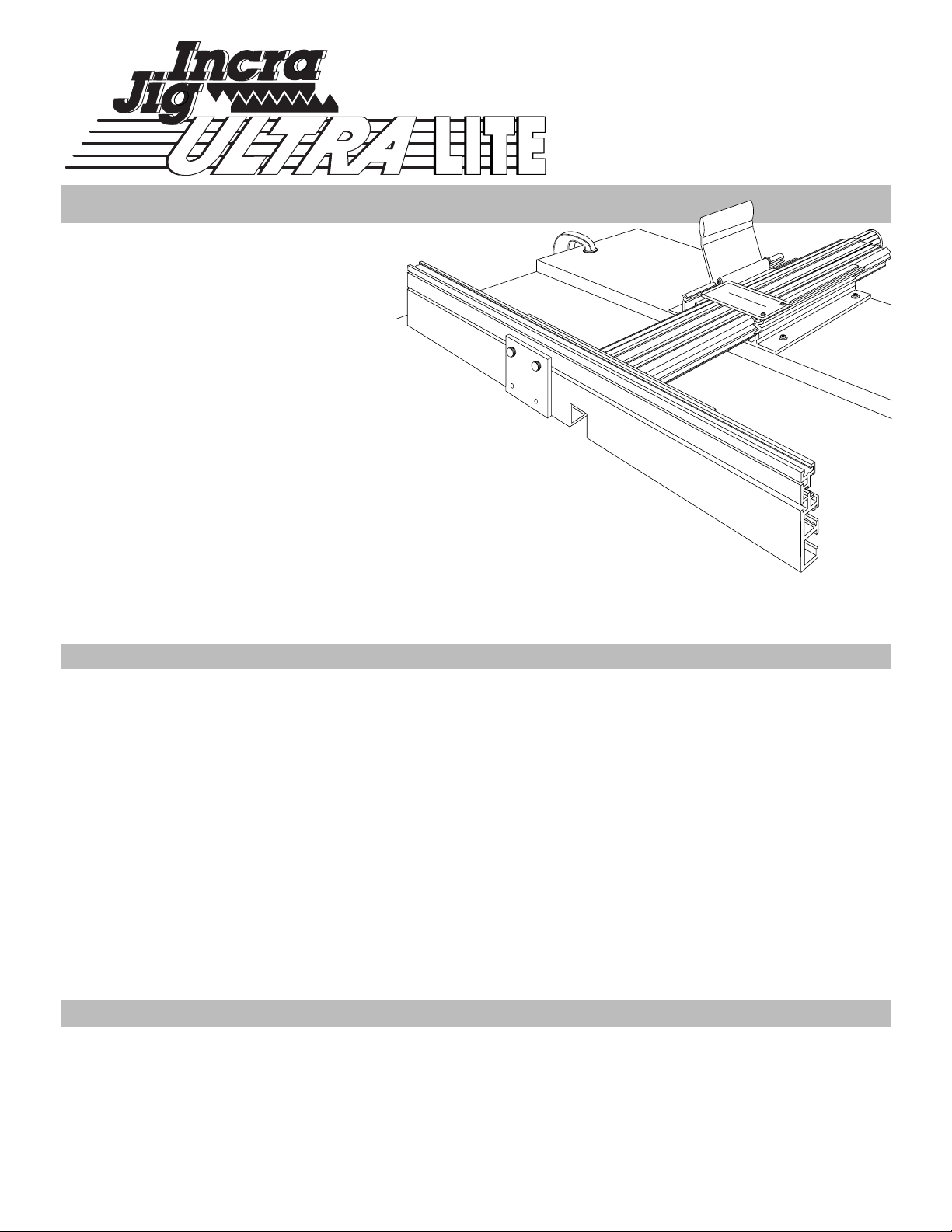
Introducing the newest member of the Incra family:
The Incra Jig Ultra Lite
. With built-in micro
adjusting, velvet smooth tracking, and the Incra heritage of precision, your new Incra Jig Ultra Lite
combines some of the best features of its big brother, the Incra Jig Ultra, in a refined, more compact
unit perfect for the router table or drill press. The Ultra Lite carries on the tradition of performance and
accuracy you’ve come to expect from the Incra line of precision tools.
From the
makers of
Incra Jig!
Setup . . . . . . . . . . . . . . . . . . . . . . . . . . . . . . . . . . . . . 2
Maintenance . . . . . . . . . . . . . . . . . . . . . . . . . . . . . . . 3
Operation . . . . . . . . . . . . . . . . . . . . . . . . . . . . . . . . . . 4
Applications/General Purpose Fence . . . . . . . . . . . . 5
Zeroing . . . . . . . . . . . . . . . . . . . . . . . . . . . . . . . . . 5
Applications/Joint Maker . . . . . . . . . . . . . . . . . . . . . 6
Setting the router bit depth of cut . . . . . . . . . . . . . . 6
Centering the bit and installing the template . . . . . . 7
Box joints . . . . . . . . . . . . . . . . . . . . . . . . . . . . . . . .10
Half blind dovetails . . . . . . . . . . . . . . . . . . . . . . . . .11
Variations . . . . . . . . . . . . . . . . . . . . . . . . . . . . . . . . . .13
Adjustments . . . . . . . . . . . . . . . . . . . . . . . . . . . . . . .14
Trouble Shooting . . . . . . . . . . . . . . . . . . . . . . . . . . . .15
Parts and Optional Accessories . . . . . . . . . . . . . . . .16
CONTENTS
■ Important safety instructions for using the Incra Jig Ultra Lite:
before using the Incra Jig Ultra Lite, read and follow all of the
instructions and safety information in this manual.
■ When using Incra Jig Ultra Lite in conjunction with any other
tool, first read and follow all instructions and safety
information in that tool’s owner’s manual.
■ When Incra Jig Ultra Lite is mounted to a wooden base or
table surface, make sure that all six mounting screws are
securely tightened and the Incra Jig Ultra Lite is firmly held in
place.
■ When using the Incra Jig Ultra Lite with a wooden base,
always make sure that the base is securely clamped,
screwed, or otherwise fastened to the work surface before
making a cut.
■ Always turn off the power and make sure that the bit or blade
is fully stationary before moving the Incra Jig Ultra Lite to any
new setting.
■ Always keep both hands behind the fence when moving the
Incra Jig Ultra Lite to any new setting.
■ Before making a cut, always make sure that the carriage
clamp is fully engaged and the jig is securely locked in place.
■ When using the Incra Jig Ultra Lite with other tools, make sure
that all safety guards and other safety equipment supplied by
the manufacturer of that tool are securely in place and
functional. Never let the Incra Jig Ultra Lite interfere with
another tool’s safety equipment.
■ Use appropriate safety devices. Keep hands clear of the bit
or blade. Always use a push stick, rubber soled push block,
or other safety devices to keep your hands safely away from
the cutting tool.
■ Wear safety glasses, hearing protection, and a dust mask,
and follow all normal shop safety practices.
■ Do not alter or modify the Incra Jig Ultra Lite in an attempt to
use it with non-Incra accessories.
SAFETY
Precision
Woodworking System
®
TM
Page 2
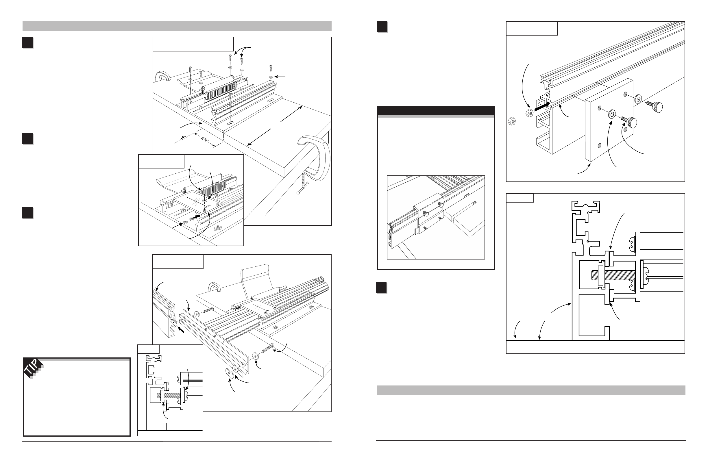
Attach the Incra Jig Ultra
Lite to a
3
/
4
” plywood base
Begin with a piece of
3
⁄
4" plywood (or
hardwood) that is 8" wide. The length of the
plywood should match the width of your
router table. Clamp the plywood to the edge
of your router table using (2) C-clamps.
Mark the center of the plywood’s length and
position the operator’s side of the Ultra Lite’s
base 2
1
⁄
4" from the center mark. See Fig. 1.
Attach the base to the plywood through the
six holes using (6) #10 x
7
⁄
8" phillips pan
head wood screws and #10 flat washers.
Attach hairline cursor
to base
Place one of the #6 flat washers on each of
the #6-32 x
3
⁄
8" screws. Insert the screws
through the holes in the plastic cursor and
loosely attach the #6-32 hex nuts. slide the
two nuts into the T-slot at the front of the
Ultra Lite’s base as shown in Fig. 1a. Align
the cursor flush with edge of the base and
tighten the mounting screws.
Attach the Incra Fence
With the plywood base still clamped to
the edge of your router table, carefully slide
the carriage into the base and pull the
carriage clamp up into the locked position.
Insert the #10-32 x 1
1
⁄
8" phillips pan head
screws through the thick (gold) washers,
then through the holes on the back of the
fence mounting bracket. Place a thin (silver)
washer on the end of each screw, then
loosely attach the rectangular nut. See
Fig. 2. The raised rim on the nut should
face toward the mounting bracket. Now
slide the thin washer and rectangular nut
into the T-slot on the back of the Incra
Fence. Make sure the thin washer is
captured in the T-slot provided as shown in
Fig 3. Position the fence so that the
mounting bracket is approximately centered
on the fence length and tighten the two
mounting screws.
FIG. 1
Attach Ultra Lite to 3⁄ 4" plywood base
FIG. 2
Attach the Incra Fence
To achieve a silky smooth
carriage motion when moving the
fence, it is important that your table
surface is flat and smooth. If you find
that your carriage tends to bind slightly
during some portion of its travel, try
loosening the fence mounting screws
then retightening at different locations
along the table’s length.
2
1
SETUP
FIG. 1a
Attach hairline cursor
3
FIG. 3
2
#10 x 7/8"
phillips pan head
wood screws
#10 washer
Center of
plywood
Align cursor flush
with edge of base
#6-32 x
3
/8" screw
#6 flat washer
#6-32 hex nuts
Incra Fence
Fence
mounting
bracket
Raised rim on rectangular nut
faces the mounting bracket
#10-32 x 1
1
/8" phillips
pan head wood screw
Thick (gold)
5
/8" o.d.
flat washer
Thin (silver) 5/8" o.d.
flat washer
Thick gold
washer
Thin silver washer
captured here
8"
Adjusting the fence angle
After mounting the Incra Fence to your
Ultra Lite, check the angle of the fence to
the router table using a machinist’s or
carpenter’s square. Sometimes, as a result
of the plywood not being perfectly flat, the
angle may be slightly more or less than 90°.
To correct the angle, place a masking tape
shim between the mounting bracket and the
fence as shown in Fig. 5.
Assemble stop positioner
Place a #8 flat washer on each of the
(2) #8-32 x
1
⁄
2" thumb screws and insert
through two of the holes in the black plastic
stop positioner. Loosely install the (2) #8-32
hex nuts, then slide the nuts into the T-slot
on the front of the Incra Fence. Fig. 4.
When not in use, simply slide the stop
positioner off the fence.
If you wish to upgrade your Incra
Fence to add the ultra-precise stop
positioning abilities of the New Incra
Stop, see the fence upgrade
package offered on page 16.
5
FIG. 4
Assemble stop positioner
FIG. 5
4
#8 flat washer
#8-32 hex nut
#8-32 x 1/2"
thumb screw
Stop
positioner
T-slot
Table
top
Place shim here if angle
is greater than 90°
Place shim here if
angle is less than 90°
Fence upgrade option:
MAINTENANCE
In general, just keeping your Incra Jig clean is all
you need to do to keep the tool in tip top shape.
Occasionally, remove the carriage from the base and
brush or blow out any sawdust or debris that may have
accumulated on the base and the UHMW guide
bearing strips. Use a toothbrush to clean the teeth
on the Incra racks on both the carriage clamp and
on the carriage.
90°
3
Page 3
Micro adjusting
The micro adjust feature of your new Incra Jig Ultra Lite allows for
precise positioning of the fence to any location between the 1⁄32" tooth
spacing of the Incra sawtoothed racks. You’ll find this feature extremely
handy the next time you need to widen a mortise by a few thousandths
of an inch for a great fitting mortise and tenon joint. Use the micro
adjuster for a flawless fit when cutting grooves to accept inlay strips,
or to loosen up a tight fitting box joint cut with an undersized bit. You’ll
find it especially useful for setup operations like “zeroing” (page 5) or
“centering” (page 7). Here’s a step-by-step look at operating your
Ultra Lite micro adjuster. See Fig. 7 as you follow the steps
Unlock the carriage clamp
Push the carriage clamp down to unlock the carriage.
Engage the micro adjust mechanism
Continue pushing the carriage clamp handle down until it
touches your plywood sub-base, then hold it there.
Micro adjust the fence position
Turn the micro adjust knob clockwise to move the fence toward
the cutter (forward), counterclockwise to move the fence away from
the cutter (backward). The carriage clamp handle must be held down
as the knob is turned.
Lock the carriage clamp
Pull the carriage clamp up to lock the carriage back in place.
Gauging the distance moved when micro adjusting is easy. A full
turn of the knob equals 1⁄32" of adjustment; a half turn equals 1⁄64".
For smaller adjustments, use the grooves on the knob as a reference.
For each groove that passes the corresponding cursor decal on the
carriage (see Fig. 8), you have moved the fence .002" (two
thousandths of an inch). At the end of the knob, you’ll find a scale
that can be aligned to read zero at any of the grooves on the knob.
This allows you to re-zero the scale after any micro adjustment.
Simply loosen the thumbscrew to rotate the scale.
The micro adjust feature of the Incra Jig Ultra Lite has as adjustment
range of +5⁄32" from mid-range. The range scale decal on the
carriage shows how much range remains in either direction. To read
the scale, just sight along the end of the black bar that holds the blue
Incra racks. When the end of the black bar is aligned with the zero
on the range scale, you are at mid-range. See Fig. 8.
OPERATION
FIG. 6
Moving fence to a new position
Although the clamping pressure has been factory adjusted,
you may wish to fine-tune the pressure to suit your individual
preference. If so, use the thin plastic shims provided and follow the
instructions shown on page 14.
FIG. 7
Micro adjusting
Moving to a new scale setting
With the plywood base clamped to the stationary tool of your choice,
moving the fence to any new scale setting is simple. First, push the
carriage clamp down and release the clamp handle to unlock the
carriage. Grasp the fence mounting bracket as shown in Fig. 6 and
slide the fence to the new position, aligning the mark on the scale or
template directly under the hairline cursor. To secure the carriage at
the new scale location, simply pull the carriage clamp handle up into
the locked position. When moving the carriage, take care not to
accidentally slide the scale in its slot. Caution: For your safety, keep
both hands behind the fence when moving to any new scale position.
FIG. 8
Micro adjust scale
1
2
3
4
First:
Push
carriage
clamp down
to unlock
carriage
Third: Pull
carriage clamp
up to lock
carriage
First: Push carriage
clamp down to “unlock”
Second: Press
clamp all the
way down and
hold.
Third: Turn
micro adjusting
knob to finetune fence
position
Fourth: Pull carriage
clamp up to lock
carriage back in place
As knob is rotated, each groove
that passes the cursor decal
on the carriage represents
.002" (two thousandths of an
inch) movement of the fence
Use the scale on the end of
the knob to accurately gauge
the distance moved. After
micro adjusting, scale on knob
can be rotated to read zero
Cursor decal
Black bar
Range scale
Micro adjust knob
Second: Grasp fence
mounting bracket and slide
fence to new position
To avoid running out of micro adjustment
range in the middle of a project, you need
to remember two things. First always micro
adjust back to mid-range before beginning a new
project. Second, whenever you need to micro
adjust a distance greater than
1
⁄32"
, use the Incra
positioning racks to get as close as possible
before reaching for the micro adjust knob.
25
26
27
28
29
30
31
0
1
2
3
4
5
6
7
8
4
5
FIG. 9
Ultra Lite at the router table
The essence of any Incra Jig is its ability to accurately
position your board for a cutting operation. In a nutshell,
it is a precision fence system. Even when used as a joint
maker, the fact is, you are simply applying a technique to
a very accurate fence system in order to produce the
various possible joints. Using your Incra Jig Ultra Lite as
a general purpose fence is just as easy as using any
other fence in your shop. In fact, it shares in common four
things that all fences have: the straight edge or fence that
your board will be pushed along as you make a cut, a
scale, a hairline cursor, and a clamp. You will use your
Incra Fence as you would any fence, that is, first you’ll
unclamp, then look through the hairline cursor as you
move the fence. When you see your measurement come
under the hairline, you’ll clamp the fence in place. Of
course, this is where the comparison ends because, unlike
other fences, when you clamp your Incra Jig Ultra Lite in
place, it is exactly where you want it to be. Just get the
mark on the scale close to the hairline cursor and the
automatic positioning controls of the patented Incra racks
move the fence to the exact location as you clamp the jig
in place. It’s just that easy. You’re sure to find many
places in your shop where the precision of the Ultra Lite
will benefit you and your work.
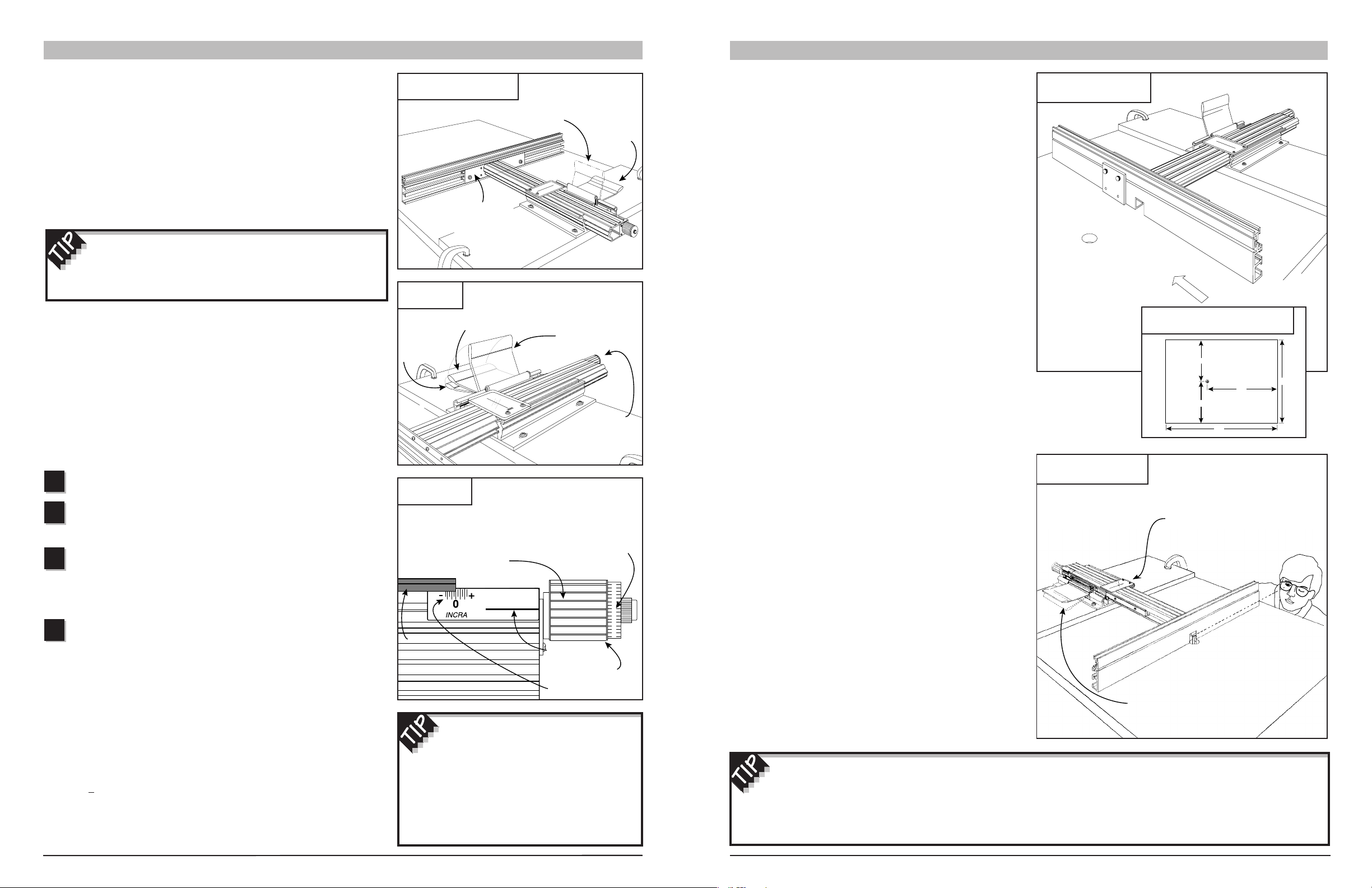
To use Incra Jig Ultra Lite at your router table, position the
plywood base on your router table top as shown in Fig. 9.
The fence should always be on the right hand side of the
router bit as seen from the operator’s side of the table.
If you do not yet own a router table top, the dimensions
shown in Fig. 10 will produce a comfortable table size
which allows enough room to use the full range of your
Incra Jig Ultra Lite. Now all you need to do is install a
router bit and “zero” the fence to the bit.
“Zeroing” the Fence to your
Router Bit
In order to ensure accurate results from any fence for
general purpose cutting, the fence must first be “zeroed”
to the cutter. To zero your Incra Fence to the cutter,
release the carriage clamp and slide the fence up to the
edge of the cutter. Sight down the length of the fence to
check for a gap between the fence and the cutter. Finetune any remaining distance by holding the clamp handle
down as you micro adjust the fence position. When the
gap of light disappears, the cutter will be “zero” distance
from the fence. Check to make sure that the router bit is
safely centered on the opening in the fence. Return the
carriage clamp to the locked position, then slide the
1
⁄
32"
scale to read 0" under the hairline cursor. See Fig. 11.
APPLICATIONS/GENERAL PURPOSE FENCE
For a truly precise “zeroed” setup, follow the
instructions above, then move your fence to a scale
reading of
1
⁄
4"
and make a test cut on a piece of scrap
stock. (Make sure the scrap stock has a square edge
and that this edge is against the fence during the cut.)
Use a pair of machinist calipers to measure the distance
between the groove and the edge of the board. If it
does not measure exactly .250" (
1
⁄
4"
), just use the
micro adjuster to accurately fine-tune the remaining
distance.
12"
12"
20"
32"
24"
FIG. 10
Router table top suggested dimensions
FIG. 11
Zeroing the fence to your bit
Feed direction
First: Unlock carriage
clamp and slide fence
up to bit
Second: Hold clamp handle down and
turn micro adjusting knob until gap
between fence and bit disappears
Third: Pull carriage clamp
up into locked position
Fourth: Slide scale to read 0"
under the hairline cursor
Page 4

6
Joint making represents one of the most exciting applications for
your new Incra Jig Ultra Lite. Just by applying a little technique to
the accuracy of your Incra Jig, you’ll soon be able to add joinery for
box and drawer making to your list of shop skills. The two templates
included with the basic set will allow you to produce equally spaced
3
⁄
8" box joints and equally spaced
1
⁄
2" half blind dovetails.
There are three important operations that must take place each
time you use your Incra Jig for joint making at the router table:
1. Setting the router bit depth of cut
2. Centering the bit on your workpiece and installing
the template
3. Cutting the joint
We’ll begin with a look at the first two operations. These are
simple setup procedures with which you will want to become
familiar. They will be used every time you prepare to cut a joint at
your router table. Beginning on page 10, we will apply these two
setup operations in a step-by-step description for cutting box joints
and half blind dovetails.
Setting the Router Bit Depth of
Cut for Box Joints
After installing the appropriate diameter straight bit for the template
pattern you have selected, (a
3
⁄
8" straight bit is required for the
Box1 template included with your Ultra Lite System) simply raise or
lower the bit in your router table to set the depth of cut at slightly
greater than the thickness of the stock you will be cutting. See
Fig. 12. Just remember, router bit manufacturers suggest that you
not cut any deeper than the diameter of the bit in any single pass.
APPLICATIONS/JOINT MAKER
FIG. 12
Depth of cut for box joints
For even more variety,
including through and
double dovetail
techniques, the optional
Incra Master Reference
Guide and Template
Library
contains a large
selection of new joinery
templates. For pricing
and ordering information,
see page 16.
FIG. 13
Set approximate depth of cut
Setting the Router Bit Depth of Cut
for Dovetail Joints
As with any half blind dovetail jig, the depth of cut of your
dovetail bit will determine how well the finished joint fits. Just a
little practice using the following steps will ensure that your
dovetail joints will always have a perfect fit.
Set the approximate depth of cut
Install the dovetail bit that corresponds to the template you
are using. (A
1
⁄
2", 14° dovetail bit is required for the DOV1
template included with your Ultra Lite System.) Raise or lower
the bit to the approximate depth of cut listed under the diagram of
your template pattern. (
1
⁄
4" for the DOV1 template, see diagram
on page 11.) Position your fence as shown in Fig. 13 so that
about half of the bit is inside the fence notch. Now slide the
1
⁄
32"
scale on your Incra Jig to read 0" under the hairline cursor.
Make the test cuts
Clamp two pieces of square cut stock to your Right Angle
Fixture. You are now going to make two dovetail cuts on the
boards as shown in Fig. 14. The spacing between these two
cuts is listed under the diagram of your selected joint pattern.
For example; if you were setting the depth of cut for the DOV1
pattern included with the Ultra Lite System, the diagram shows:
Spacing to set depth of cut =
7
⁄
8". Using the
1
⁄
32" scale set in
Step 1, you would make a cut at the 0" setting, then move to
7
⁄
8"
to make the second cut.
1
2
Raise or lower bit to
slightly greater than
the thickness of
your stock
Board to be joined
First: Set bit height
to recommended
approximate depth of cut
More Joinery Templates
FIG. 14
Make the test cuts
Second: Position the fence
so that about half of the bit
is inside the fence notch
Third: Slide the 1/32" scale
to read 0" under the cursor
First: Clamp two
boards to Right Angle
Fixture
Second: Make
a cut at the 0"
setting
Third: Move fence
back to dimension listed
under diagram of your
joint pattern (7/8" for
DOV1 pattern) and
make second
cut
Centering the Router Bit on your
Workpiece
After setting your router bit depth of cut, you need to
position your Incra Jig and install the joinery template so
that all the cuts are made in the right places on your
wood. This is accomplished through a setup operation
called “centering”. Centering locates your Incra Jig so
that the router bit is aligned with the center of the stock
width you wish to use. Once you find the center, install
the selected template and you’ll be ready to cut a
perfect joint. The simple steps to follow should always
be used when setting up your Incra Jig for joint making.
Align board with bit
Begin by cutting a piece of
3
⁄
4" thick stock to the
same width as the boards you wish to join later on. Mark
the center of this piece’s width on one end and place
the board face down on the router table with the center
of the board aligned with the approximate center of the
bit. See Fig. 17.
Set initial fence position
Unlock the carriage clamp and slide the fence up to
the edge of the board, then lock the carriage clamp
back in place. See Fig. 18. Make sure the center mark
on the board is still aligned with the approximate center
of the router bit.
Test the fit and adjust as necessary
Unclamp the two boards and test the fit by joining
them as shown in Fig. 15. As with any half blind dovetail
jig, a little trial and error is needed to achieve a snug
fitting joint. To tighten the fit, raise the bit up slightly; to
loosen the fit, lower the bit slightly. Just remember this
phrase: “Heighten to tighten, lower to loosen.” After
adjusting the bit height, make a new set of trial cuts on
the opposite end of the boards. After a few adjustments
and trial cuts, you’ll have a perfect fit. If you’ll mark the
properly fitting cuts on one edge of the boards, you can
save this piece to use as a depth gauge the next time
you set up this particular bit for joinery.
7
FIG. 15
Test the fit
When the fit is too loose, the trial cuts provide a
gauge to let you know how much to raise the bit. Just
join the trial pieces end to end and gently pull the boards
to wedge the dovetails together. The gap that appears is
equal to the distance you need to raise your dovetail bit to
achieve a tight fit. See Fig. 16.
FIG. 16
FIG. 17
Align board with bit
FIG. 18
Set initial fence position
2
1
3
Gap
Raise bit this much
Mark center
of board
Center of board
aligned with
approximate
center of bit
First: Unlock
carriage clamp
Second: Slide fence
up to edge of board
Third: Lock carriage
clamp back in place
Page 5

8
FIG. 19
Rout the test groove
Rout the test groove
Turn the router on, and using a good rubber soled push
block, cut a groove along the entire length of the board. See
Fig. 19. Now turn the stock end for end with the groove still
face down and make a second pass over the router bit. The
second pass should widen the groove slightly (unless you are
already perfectly centered). Make sure you have turned the
stock end for end before making the second pass. (This
places the center mark at the back of the board.)
Fine-tune the fence position
With the router unplugged, turn the bit to its widest cut
angle (viewed from the infeed side of the router table). Place
the board against the fence with the router bit just inside the
test groove cut. There should be a small gap between the
edge of the bit and one side of the groove. See Fig. 20.
Now all that is needed is to micro adjust the fence position so
that with the board against the fence, the bit is in the center
of the groove. Use the Ultra Lite’s micro adjuster to move the
fence until there appears to be an equal gap on both sides of
the router bit. See Fig. 21. Once the bit is in the middle of
the groove, make sure to lock the carriage clamp in place.
FIG. 20
Position board against fence
with bit just inside the groove
FIG. 21
Micro adjust fence to place bit
in the middle of the groove
4
3
First: Rout a groove along
the entire length of the stock
Second: Turn
end for end
and make a
second pass
over the bit
Small gap on one
side of the bit
Equal gap on
both sides of bit
This is a large template and must be output accurately,
Please, call us and we will send you this template.
972-418-4811
Once you have successfully found the center of the
board’s width with your router bit, slide the template you
have selected for joinery into one of the scale slots on your
Incra Jig’s carriage. This must always be done with the
carriage still locked at the center position you just found. Slide
the template until the suggested center cut on the template is
directly under the hairline cursor. You’ll find the suggested
center cut listed under the diagram of each template pattern
shown above. You are now ready to cut the joint.
9
5
FIG. 22
Install the Incra template
FIG. 23
With the jig still locked at the
center of your board, slide the
template in to position the “center
cut” under the hairline cursor
In order to save wood when centering the bit on
wide stock, just leave one of the boards you’ve cut for
your box about an inch to two longer than necessary. Clamp
this piece to your Right Angle Fixture as shown in Fig. 23
and make the test cuts described in Step 3 through the end
of the board, flipping the piece edge for edge before making
the second cut. After you are centered, just crosscut the
extra length off of the board’s end.
This is a large template and must be output accurately,
Please, call us and we will send you this template.
972-418-4811
TEMPLATE: DOV1
BIT TYPE: 1/2” 14° DOVETAIL
APPROX. DEPTH OF CUT: 1/4”
SPACING TO SET DEPTH OF CUT: 7/8”
DOV1BOX1
SUGGESTED CENTER CUT: 8B
APPROX. RABBET WIDTH: 7/32”
APPROX. STOCK THICKNESS: 1/2”
TEMPLATE: BOX1
BIT TYPE: 3/8” STRAIGHT
APPROX. STOCK THICKNESS: 3/8”
APPROX. DEPTH OF CUT: 3/8”
SUGGESTED CENTER CUT: 9B
Page 6

10
The first cut on either the
“A” or “B” series of cuts will be
an open cut. This means you
will be cutting away the edge of
the board adjacent to the fence.
To keep this edge cut clean and
splinterfree, begin with a light
1
⁄
32"
wide scoring pass, then sneak up
to the first template mark in
several light side-by-side passes.
See Fig. 28.
FIG. 26
Make the “A” cuts
Backing board to
prevent splintering
FIG. 27
Make the “B” cuts
Backing board to
prevent splintering
FIG. 28
Fence
open cut
One of the easiest of the
many interlocking joints that
can be cut with your Incra
Jig, box joints provide a
good introduction to the use of the
Ultra Lite and the joinery templates for joint
making. Just follow these steps to learn how:
You’ll want to begin by cutting your stock to the lengths
and widths necessary for your box construction. Also
cut a piece of
3
⁄
4" thick stock to the same width for use in
centering later on.
Install a
3
⁄
8" straight bit in your router table and set the
depth of cut to slightly greater than the thickness of
your stock.
Center the bit on your stock width and install the
template. Use the centering method described on
page 7 to find the center of your board’s width with the
router bit, Fig. 25. Remember, the board used for the test
cuts must be the same width as the pieces you will be
joining later on. After finding the center, slide the BOX1
template into one of the auxiliary scale slots and position the
suggested center cut (9B) directly under the hairline cursor.
Clamp two of your boards to the Right Angle Fixture
with a backing board as shown in Fig. 26. (You can use
your centering board from Step 3 as a backing board if you
like.) The backing board is used to prevent splintering as
the router bit exits the cut. Make cuts at the “A” marks on
the template. Of course, you will only need to make the “A”
cuts that position the boards in line with the router bit. After
completing the cuts, flip the boards end for end and repeat
the same cuts. Now clamp the remaining two boards with a
backing board to the Right Angle Fixture as shown in Fig. 27
and make the “B” series of cuts. Repeat these “B” cuts on
the opposite end of the boards.
Too tight or too loose?
Check the fit of your completed pieces. If the joint is too tight
or too loose, the problem is the router bit, not your Incra Jig.
An oversized bit will create a loose fit, while an undersized bit
will cut a tight joint. To loosen the tight fitting joint, you can
micro adjust the fence backward about five thousandths of an
inch and then re-cut one of the series of cuts.
FIG. 24
Set depth of cut
FIG. 25
Center bit on your stock width
1
2
3
Board to be joined
Depth of cut set slightly
greater than thickness
of stock
See Steps 1-5 starting on page 7
for complete centering instructions
Box Joints
4
Make several
light side-by-side
passes when
making open cut
adjacent to fence
Half Blind Dovetails
The easiest of the dovetail
joints, half blind dovetails add
strength and beauty to your
joinery. They are also the most
versatile of the many joints you
can cut with your Incra Jig. In fact,
many of the decorative joints we’ve
designed over the years are just variations
on the half blind technique you are about to learn. Once
you’ve mastered the steps below, you’ll find these
decorative joints (described in the optional
Incra Master
Reference Guide and Template Library
and in the
Incra Jig
Projects & Techniques
book) quite easy to complete.
You’ll want to begin by cutting your stock to the
lengths and widths necessary for your box
construction. Also cut a piece of
3
⁄
4" thick stock to the
same width to use in centering later on.
Install a
1
⁄
2" 14° dovetail bit in your router table and
set the depth of cut as described on page 6.
The two trial cuts should be spaced
7
⁄
8" apart for the
DOV1 template.
Center the bit on your stock width and install the
template. Use the centering method described on
page 7 to find the center of your board’s width.
Remember, the board used for the test cuts must be
the same width as the pieces you will be joining later on.
After finding the center, slide the DOV1 template into one
of the auxiliary scale slots and position the suggested
center cut (8B) directly under the hairline cursor.
Determine the Pin and Tail cuts. Fig. 31 details the
characteristics of a properly cut pin board and tail
board. You’ll notice that the tail board always begins and
ends with open cuts, while a pin board will always have
solid stock on its edges. As a result, it is important at this
point to determine which series of cuts (“A” or “B”) will be
used for the tail boards and which series will be used for
the pin boards. To do this, turn to the full sized diagram for
the DOV1 template shown on pages 8-9. With a pencil,
mark the center of the width of one of the boards to be
joined. Align the pencil mark with the center cut mark (8B)
on the drawing, see Fig. 32. On one side of the plans, the
outer edges of the board will overlap grooves. The series
of cuts on that side of the drawing will
become the tail cuts. On the other
side of the plans, the outer edges of
the board will overlap shaded pins on
the drawing. The series of cuts on
that side will become the pin cuts. In
the example shown in Fig. 32, you can
see the edges of the board overlap
grooves on the “A” side of the drawing.
The “A” series of cuts will be used for
the tails. The edges of the board
overlap shaded pins on the “B” side of
the drawing. The “B” series of cuts will
be used to cut the pins.
11
1
2
3
4
FIG. 29
Set depth of cut
See Steps 1-3 starting on page 6 for
complete depth of cut instructions
FIG. 30
Center the bit on your stock width
See Steps 1-5 starting on page 7
for complete centering instructions
FIG. 31
Pins and tails – half blind dovetails
Tail boards are always cut
VERTICALLY clamped to
the Right Angle Fixture
The first and
last cuts on
the tail boards
are always “open
cuts”. This
means the edges
are cut away
Tail boards always
begin with a dovetail
shaped rabbet
Pin boards will always
have half pins (solid
stock) on the outer
edges of the board
Pin boards are cut
FACE DOWN on the
router table
FIG. 32
Determine the pin
and tail cuts
Pins
Tails
Template: DOV1 Approx. Depth of Cut:1⁄4" Suggested Center Cut: 8B
Approx. Stock Thickness – Half Blind:
1
⁄2" – Through:1⁄4"
Bit Type:
1
⁄2" 14° Dovetail Spacing to Set Depth of Cut:7⁄8" Approx. Rabbet Width:7⁄32"
Page 7

Tail Cuts
To cut the tails for a half blind dovetail, begin by
cutting a dovetail shaped rabbet on both ends of the
two boards, see Figs. 33 and 33a. The rabbet needs to
be
7
⁄
32" wide. Do not cut the rabbet width in one pass.
Instead, use three or four light side by side passes to
sneak up on the rabbet width. You can use the
1
⁄
32" scale
in your Ultra Lite as a reference so you’ll know how much
you have widened the rabbet with each pass.
Now clamp the two tail boards to your Right Angle
Fixture as shown in Fig. 34, and make the tail series
of cuts that you determined in Step 4. As always, using
good router technique, sneak up to the first tail cut in
several light side-by-side passes to avoid splintering the
edge of the stock (see Tip on page 10). After completing
the cuts, flip the boards end for end and repeat the cuts.
Pin Cuts
Set your Incra Jig to the first pin cut on the template
that places the bit in front of the fence. Slide the
stop positioner onto the fence and locate the stop as
close to the dovetail bit as possible (without actually
touching the bit) and clamp in place. See Fig. 35. The
stop positioner will be used to limit the length of the pin
cuts.
Place one of the pin boards face down on the router table
as shown in Fig. 36 and make the pin series of cuts
determined in Step 4. Be sure to use a good rubber
soled push block as shown. Make the cuts on only one
end of the board for now. After making the cuts, check
the fit between this board and one of the tail boards. If
the tails won’t fit all the way into the pin sockets, simply
lengthen the pin cuts by moving the stop positioner away
from the router bit. (See Tip below.) Recut the pin board
and again check the fit. Once you have a flush fit, make
the pin cuts on the opposite end of the board and on both
ends of the remaining piece.
5
6
7
FIG. 37
Move stop
back this far
to achieve a
flush fit
FIG. 33
Cut the rabbets
Dovetail shaped rabbet
cuts on both ends of
the tail boards
Rubber soled
push block
FIG. 33a
Rabbet width
7
⁄ 32"
rabbet
After making your first series of cuts, check the fit
with one of the tail boards. If the tail board won’t fit
all the way into the pin board, just measure the
distance it protrudes. See Fig. 37. This is the distance
you need to move the stop away from the bit to achieve a
flush fit.
Pin board
Tail board
FIG. 34
Cut the tails
Wooden
handscrew
clamp
FIG. 35
Set stop positioner
Position stop on
outfeed side of
bit as close as
possible to the
cutter
FIG. 36
Cut the pins
Rubber soled
push block
Clamp two boards
with rabbets facing
out as shown
Stop
positioner
Fence
12
13
After making a half blind dovetail, you may notice that the
joint looks symmetrical, but the edges of the two boards do
not align flush, see Fig. 38. This simply means that when
you centered the board using the method described in
your owner’s manual or
Incra Master Reference Guide and
Template Library
, you were close but not quite perfect. Of
course practice makes perfect, but there is another method
for cutting the tail boards that will ensure a flush alignment
regardless of how well your board was centered. Just
make sure when you clamp the tail boards to the Right
Angle Fixture that the dovetail shaped rabbets on all the
boards face the cutter, see Fig. 39. That’s all it takes!
Remember that even if you use this procedure, you should
still center first to ensure a symmetrical looking joint.
FIG. 38
Boards
not
aligned
flush
Dovetail shaped
rabbet cuts
face the cutter
Not
flush
FIG. 39
VARIATIONS
The drawings at right show a standard equally spaced
dovetail joint (Fig. 40) and several variably spaced dovetail
joints (Fig. 41). Although these joint patterns look quite
different from one another, they all have one thing in
common. They are all made using the same equally
spaced dovetail template. By learning the variations
technique described below, you can customize the joint
pattern produced by any template. This technique works not
only for half blind dovetails as pictured, but also for box
joints, through dovetails, and with a little study, you can
even customize the decorative Double and Double-Double
joints. In general, pattern variations can be designed by
observing a few simple rules.
Select cuts to be left out
Align the center of your board with the center cut you
plan to use on the diagram. Then choose the cuts you
want to leave off on one* side of the diagram. Determine
which side of the diagram will be the pin cuts and which will
be the tails (see Step 4 on page 11). Leaving cuts off of
the tail side of the diagram creates wider tails. (See
Example 1 on Fig. 41.) Leaving cuts off of the pin side of
the diagram creates wider pins.
*
Although a bit more complicated, cuts can be left off of both
sides of the diagram, resulting in a pattern variation that has
both wider pins and wider tails. (see Example 3, Fig. 41)
Always modify the pattern
symmetrically
For example: if you decide to leave out the
first
two “A” cuts
on your stock’s width, you must also leave off the
last
two
“A” cuts.
Cut the joint
Any cuts left out on one side of a pattern will be used
to modify the other side. If you decide, for example, to
leave off cuts 2A and 7A when you are cutting the “A” cut
boards, just make cuts 2A and 7A along with all of the “B”
cuts to automatically modify the “B” cut boards.
BEGINNER’S TIP
2
3
FIG. 40
FIG. 41
Equally spaced
dovetail
Tails Pins
EXAMPLE 1
Tails Pins
EXAMPLE 2
Tails Pins
EXAMPLE 3
FIG. 42
Designing
the pattern
variation
FIRST: Align center of board with “center cut” on diagram
SECOND: Determine which cuts will be pins and which will be tails.
(Step 4, page 11)
THIRD: Decide if you want the pins or the tails to be wider.
Example: Leaving out the “A” cuts will create wider tails; Leaving
out the “B” cuts will create wider pins.
FOURTH: Write down or circle the cuts you wish to leave out.
Center of
board
aligned
with
“center
cut”
Dovetail bit
1
Page 8

14
All of the components and features of your new Incra Jig
Ultra Lite have been factory set and should require no
further adjustment. If, however, you wish to recalibrate
these components, the following information is provided to
assist in performing the adjustments.
Adjusting the Clamping Pressure
The Ultra Lite carriage clamp was designed to make it
easy for the operator to adjust the clamping pressure to
his/her own individual preference using the supplied clamp
pad shims. Here’s how:
Note: The Ultra Lite must be attached to a
3
⁄
4" plywood
base with all six mounting screws (see Fig. 1, page 2)
before adjusting the clamping pressure.
Unlock the carriage clamp and remove the phillips head
screw and washer that caps either end of the clamp pad
slot. See Fig. 43. Your hardware pack for the Ultra Lite
includes (3) .005" x
7
⁄
8" x 4" clamp pad shims. If you want
to increase the clamping pressure, add one of the shims,
check the clamping pressure and adjust further as
necessary. The shims should be placed to the left of the
1
⁄
8" thick clamp pad shown in Fig. 43, so that the clamp
always touches the
1
⁄
8" thick pad, and not the thin shims.
To decrease the clamping pressure, simply remove one of
the existing thin shims. When you are satisfied with the
clamping pressure, replace the phillips head screw and
washer.
Caution: If you have decreased clamping pressure by
removing a shim, make certain that adequate pressure
remains to hold the carriage rigidly in place when clamped
in the fully extended position.
Realigning the Carriage Racks
Unlock the carriage clamp and slide the carriage so you
can access the two phillips head screws that hold the rear
Incra rack to the black mounting track. Tighten the two
screws. Next, slide the carriage forward for access and
loosen the two screws that hold the front Incra rack. The
two racks should be spaced about 2" apart. Adjust the
spacing by sliding the loose rack as necessary. Now
position the carriage in the base so that when the carriage
clamp is pulled up into the locked position the short blue
clamping rack in the base bridges the gap between the
two racks on the carriage. See Fig. 44. Tighten the one
rack mounting screw that you have access to. Finally,
unclamp the carriage clamp and slide the carriage forward
to allow access to the remaining screw and tighten.
ADJUSTMENTS
FIG. 43
Adjusting the clamping pressure
First: Unlock carriage clamp
Second: Remove phillips
head screw and washer
Third: Add or remove shims to
the left of
1
⁄8" clamp pad
Shim
FIG. 44
Realigning carriage racks
First: Slide carriage
for access and
tighten screws on
rear rack
Second: Slide carriage for access
and loosen screws on front rack
Third: Position carriage so that short clamping rack
will clamp the ends of both
of the longer racks and
lock carriage clamp in place
Fourth: Tighten front screw
Fifth: Slide carriage forward
and tighten remaining screw
2" approx.
1
⁄8" clamp pad
15
TROUBLE SHOOTING GUIDE
Symptom
Carriage clamping
pressure is too tight
or too loose.
LEXAN™ scale or
template is difficult
to slide in scale slot.
Racks do not mesh
properly when
engaging the
carriage clamp.
When the jig is
moved to a new
position the carriage
does not glide
easily.
Fence is not square
to the table surface
at all jig positions.
Micro adjusting
knob will not rotate
or is difficult to
rotate.
Micro adjusting
knob rotates but no
movement of the
carriage or fence.
Probable Cause
Carriage clamp not adjusted
properly.
Dirty scale slot.
Sawdust on racks.
Scale mark is not aligned
directly under the hairline
cursor.
Carriage racks are
improperly aligned.
Fence is improperly mounted
to the carriage.
Router table surface not flat.
Fence is improperly mounted
to the carriage.
There are several possible
causes: Jig mounting board
is not flat, table is not flat,
debris between table and
mounting board or between
mounting board and jig.
Carriage clamp is not
“unlocked”.
Jig is micro adjusted to the
end of the forward travel
range.
Jig not in micro adjusting
mode.
Jig micro adjusted beyond
end of backward travel
range.
Solution
Adjust clamping pressure. See page 14.
Remove the scale and clean with paste wax or preferably, Top-Cote
(available from your Incra dealer). CAUTION: DO NOT allow wet
Top-Cote to come into contact with LEXAN scale or templates, or any
other plastic material.
Remove all debris from the racks’ teeth with a stiff brush, such as a tooth
brush. DO NOT attempt to clean the racks with solvents of any kind as this
may damage them.
After zeroing to a cutter, or after centering when joint making, make sure
the carriage clamp is pulled into the locked position before sliding the
scale or template into place and that the 0" or center cut mark is
positioned directly under the hairline cursor. When you begin your series
of cuts thereafter, always make sure the scale or template mark is aligned
directly under the hairline cursor BEFORE locking the carriage clamp.
Realign the carriage racks as described on page 14.
If the fence is mounted too high or too low on the carriage, it can cause
resistance when moving from one position to another. If this is the case
loosen the screws holding the fence and realign. See Step 3 page 2.
Bumps or dips on the table surface can force the carriage into non-parallel
alignment with the base. Check the table for flatness and correct as
necessary.
If the fence is mounted too high or too low on the carriage, it can change
the angle of the fence relative to the table when it is moved from one
position to another. If this is the case, loosen the screws holding the fence
and realign. See Step 3 page 2.
If you identify any of these, take steps to correct the problem. You can
also use shims to bring the fence into perfect square as described in
Step 5 on page 3.
Carriage clamp must be unlocked, then the clamp handle must be pushed
down and held to place the jig in the micro adjust mode. See Steps 1-4
page 4.
Micro adjust back to mid-range position as indicated by the micro adjust
range scale. Turn knob counter clockwise until “0” on the scale is aligned
with the end of the black bar on the far side of the carriage. See Fig. 8
page 4.
After unlocking the carriage clamp, the clamp handle must be pushed
down and held to place the jig in the micro adjust mode. See Steps 1-4
page 4.
Micro adjust jig forward to mid-range as indicated by the micro adjust range
scale. Turn knob clockwise until the “0” on the scale is aligned with the end
of the black bar on the far side of the carriage, see Fig. 8 page 4.
Page 9

16
Made in the U.S.A. by Taylor Design Group, Inc.
0299
Printed in the U.S.A. © 1999, 1996 Taylor Design Group, Inc. Incra is a registered trademark of Taylor Design Group, Inc.
Part # Part Description Price
IJUL-CURSOR Hairline Cursor (with mounting hardware) $ 4.95
IJUL-STOP Stop Positioner (with mounting hardware) as shown in Fig. 4 on page 3 $ 6.95
IJUL-FENCEUP Fence upgrade kit. Includes: (1) Incra Stop (premium model) $24.95
(4)
1
⁄32" Incra racks
(1) 16" long
1
⁄32" scale
Mounting hardware
MTL2
Incra Master Reference Guide and Template Library
$24.95
Exciting new joinery techniques plus 38 new patterns to choose
IJPT1
Incra Jig Projects & Techniques Book
$22.95
Features 14 original Incra projects, 4 exclusive new Incra joints, and
a wealth of tips and techniques that will help you master the Incra Jig
IJUL-MMRACK Metric conversion kit — set of 3 metric racks with 430mm metric scale $ 6.95
IJU-MMSCALE 430mm metric scale $ 2.95
IJU-32SCALE 16" long
1
⁄32" scale (set of 2) $ 3.95
PUSHBLOCK Rubber soled push blocks $ 7.95
PARTS AND OPTIONAL ACCESSORIES
PRODUCT INFORMATION
For a product information update on the complete
Incra line of tools, please see your nearest dealer.
If you are unable to locate a store nearby, or if you
have trouble finding a particular product, we will honor
your order directly.
For a product information brochure, call, write or fax to:
Taylor Design Group, Inc.
P.O. Box 810262, Dallas, TX 75381
Tel: (972) 418-4811 Fax: (972) 243-4277
Web Site: www.incra.com
WARRANTY
Taylor Design Group, Inc. warrants this product for one year from date of purchase. We will repair any defects due to
faulty material or workmanship, or at our option, replace the product free of charge. Please return the failing component
only, postage prepaid, along with a description of the problem to the address below. This warranty does not apply to
parts which have been subjected to improper use, alteration, or abuse.
LIFETIME WARRANTY ON POSITIONING RACKS
If an Incra positioning rack in this tool becomes damaged for ANY reason, Taylor Design Group will replace it free of
charge for as long as you own your tool. Return the damaged rack, postage prepaid, and allow 1 to 2 weeks for delivery.
NOTE:
Replacements cannot be sent unless damaged racks have been received by Taylor Design Group.
 Loading...