

Page 1
®
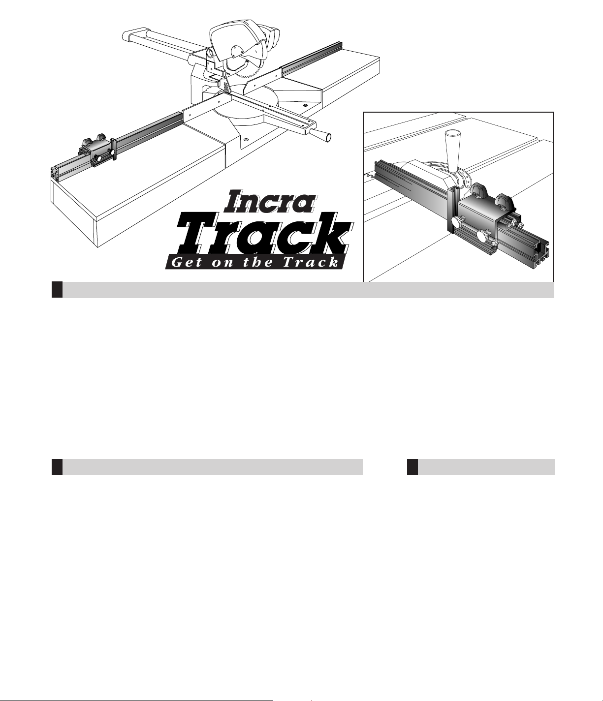
SYSTEM OWNER’S MANUAL
hat does an INCRA tool do better than any other? Just ask
that question to any of the thousands of satisfied INCRA router
table or table saw fence owners and they’ll all give the same
answer, “It positions your work with perfect accuracy and repeatability.”
Over the years, many of these same customers have requested a
means of adding these benefits to many of the other tools in their
shops. Your new INCRA Track does just this by providing the same
patented automatic positioning control used on the famous INCRA Jig
in a versatile track system. Combined with the modular design of the
INCRA Shop Stop, you'll be able to add INCRA precision to virtually
every jig, fixture, miter gauge, and stationary tool in your shop.
W
CONTENTS
General Mounting Instructions
Slotted Hole Mount
. . . . . . 2
Rear T -slot Mount
. . . . . . . 2
Bottom T -slot Mount
. . . . . . 2
Attaching the Racks . . . . . . . 3
Positioning the Scales . . . . . . 3
Auxiliary Fences . . . . . . . . . . 4
Applications . . . . . . . . . . . . . . 5
Miter Gauge
. . . . . . . . . . . 5
Jigs and Fixtures
. . . . . . . 6
Miter, Compound Miter,
and Radial Arm Saw
. . . . . 7
Drill Press
. . . . . . . . . . . . . 7
SAFETY
Important safety instructions for using the INCRA Track System:
◆ Before using the INCRA Track, read and follow all of the instructions and
safety information in this manual.
◆ When using the INCRA Track in conjunction with any other tool, first read and
follow all instructions and safety information in that tool’s owner’s manual.
◆ Use appropriate safety devices. Keep hands clear of the bit or blade. Always
use a push stick, rubber soled push block, or other safety devices to keep
your hands safely away from the cutting tool.
◆ Never let any part of the INCRA Track interfere with another tool’s safety
guards or other safety equipment.
◆ Never let the bit or blade come into contact with the aluminum body of the
INCRA Track.
◆ Always turn off the power and make sure the bit or blade has come to a
complete stop before changing the setting of any part of the INCRA Track or
INCRA Shop Stop.
◆ Wear safety glasses, hearing protection, and follow all normal shop safety
practices.
From the
makers of
INCRA JIG
FOR USE WITH …
◆
Miter Gauge
◆
Jigs & Fixtures
◆
Miter Saws
◆
Radial Arm Saws
◆
Compound Saws
◆
Drill Press Fence
◆
INCRA Jig
Page 2
GENERAL MOUNTING INSTRUCTIONS
Your INCRA Track is designed to provide a variety of mounting options to meet the requirements of your applications.
Each mounting option offers certain benefits. When considering a mounting preference, check the benefits of each
option. In some applications, you may find combinations of two or more mounting options are useful.
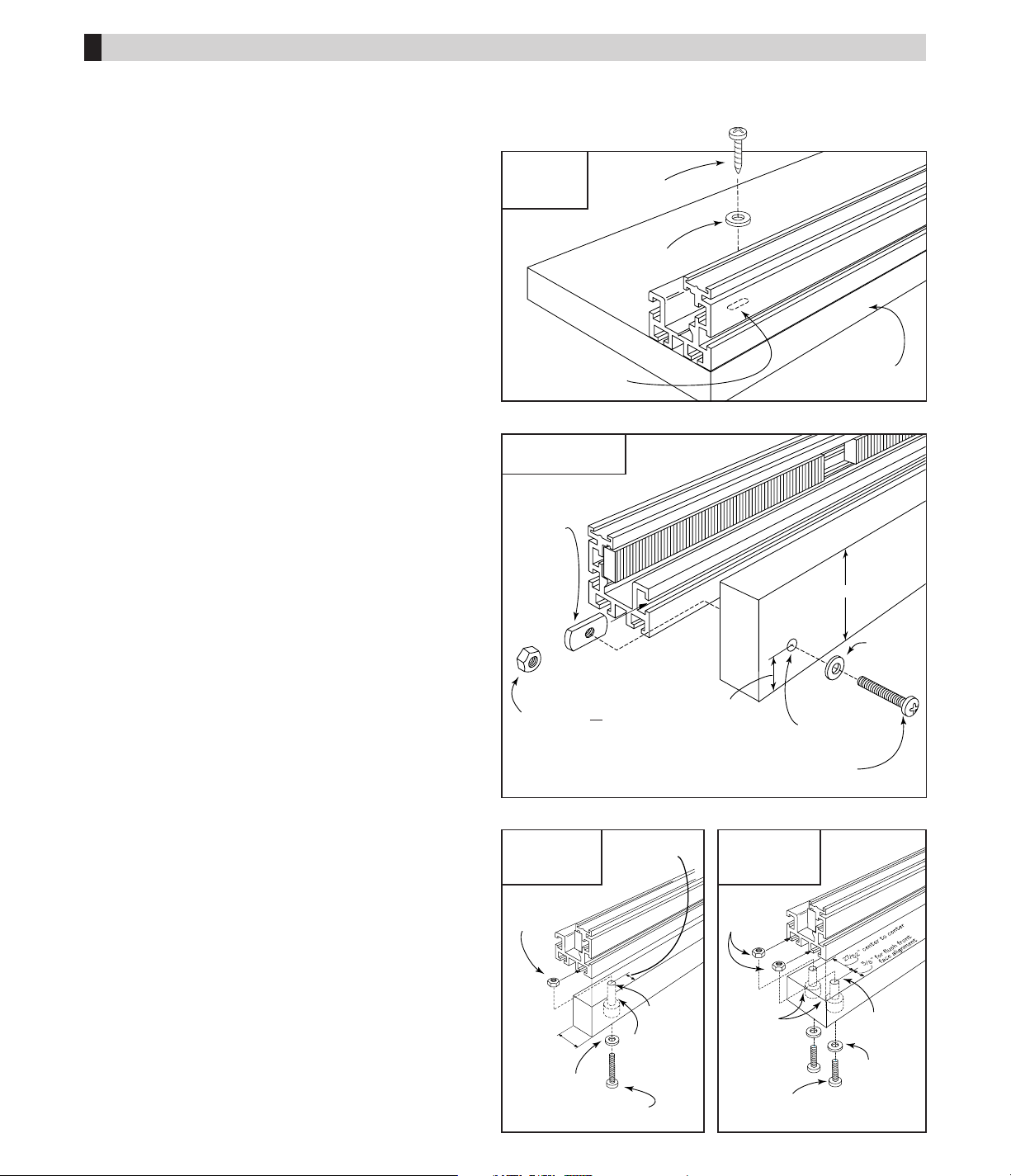
Option #1: Slotted Hole Mount –
(Fig. 1)
Benefits:
◆
Quick and easy mounting
◆
Good for fixed INCRA Track applications
Applications:
. . . . . . . . . . . . . . . . . . . . . . . . . . . .
Page
◆
Jigs & Fixtures . . . . . . . . . . . . . . . . . . . . . . . . . 6
◆
Sliding Crosscut Boxes . . . . . . . . . . . . . . . . . . . 6
◆
Drill Press Fence . . . . . . . . . . . . . . . . . . . . . . . 7
◆
Miter and Compound Miter Saws . . . . . . . . . . . 7
Note:
When using the slotted hole mounting, always screw
the INCRA Track to your application before adding the
INCRA saw toothed racks.
Option #2: Rear T-slot Mount –
(Fig. 2)
Benefits:
◆
Allows for sliding the INCRA Track relative to applications
◆
Good for applications where the ability to slide the fence
toward or away from the cutter is important
◆
Enables quick removal of INCRA Track from application
Applications:
. . . . . . . . . . . . . . . . . . . . . . . . . . . .
Page
◆
Miter Gauge . . . . . . . . . . . . . . . . . . . . . . . . . . . 5
◆
Jigs and Fixtures . . . . . . . . . . . . . . . . . . . . . . . 6
◆
Radial Arm Saw . . . . . . . . . . . . . . . . . . . . . . . . 7
◆
Compound Miter Saw . . . . . . . . . . . . . . . . . . . . 7
Note:
When using any T-slot mount, first install screws and
washers through your application and loosely attach nuts.
Then slide nuts into the T-slots on the INCRA Track.
Note:
If your application requires a vertical attachment point
for the INCRA Track that is taller than 13⁄4", just place a
1
⁄2" thick spacer block no taller than 13⁄4" between the
application and the rear of the INCRA Track.
Option #3: Bottom T-slot Mount –
(Figs. 3 & 4)
Benefits:
◆
Allows mounting to the 3/4" edge of a piece of plywood
◆
Good for applications requiring a taller fence
◆
Use for fixed or sliding track applications
Applications:
. . . . . . . . . . . . . . . . . . . . . . . . . . . .
Page
◆
Miter Gauge . . . . . . . . . . . . . . . . . . . . . . . . . . . 5
◆
Jigs & Fixtures . . . . . . . . . . . . . . . . . . . . . . . . . 6
◆
Drill Press Fence . . . . . . . . . . . . . . . . . . . . . . . 7
Note:
When using any T-slot mount, first install screws
and washers through your application and loosely
attach nuts. Then slide nuts into T-slots on the
INCRA Track.
FIG. 1
Slotted hole
mount
FIG. 2
Rear T-slot mount
FIG. 3
Bottom T-slot
mount (single)
FIG. 4
Bottom T-slot
mount (double)
#10-32
rectangular nut
(supplied)
1
/4-20 hex or square nut
(If using 1/4 -20 mounting
hardware, drill 5/16" thru hole)
or
1
/4 "
thru hole
#10 flat
washer
#10-32 machine screw
(Adjust length for application)
#10-32
hex nut
3
/4"
3
/8"
(for flush
front face
alignment)
#10-32 machine screw
(Adjust length for application)
#10 flat washer
#10 flat
washer
#10-32
hex nuts
#10-32 machine screw
(Adjust length for application)
9
/16" or
5
/8" dia.
counterbore
1
/4" dia.
thru hole
1
/4" dia.
thru hole
1
3
/4" max.
#10 x 1"
wood screw
#10 flat
washer
Slotted holes
5
/8"
2
INCRA Woodworking Tools & Precision Rules
Plywood or
hardwood base
9
/16" or
5
/8" dia.
counterbore
Page 3
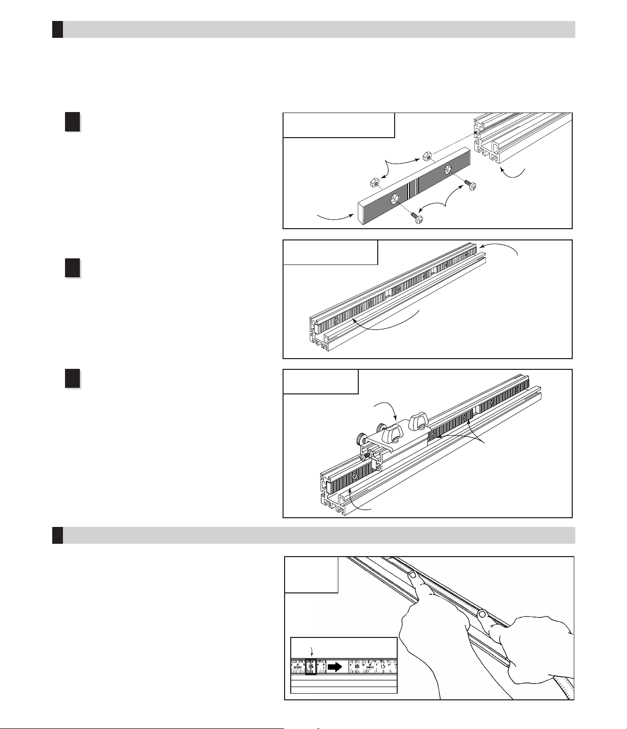
Insert the #8-32 x 3⁄8" machine screws through
the INCRA racks as shown and loosely install the
hex nuts. Slide the hex nuts into the T-slot on your
INCRA Track.
Note:
Some track sections may include both 4" and
6" racks. Use all racks supplied in any order.
(Fig. 5)
Note:
If you will be using the slotted hole mounting as
described in Fig. 1, always screw the INCRA Track to
your application before adding the INCRA sawtoothed racks.
After sliding all of the supplied racks onto
your INCRA Track, align the rack at one end
flush with the end of the track and tighten the
screws for this rack only. Evenly space the
remaining racks along the length of your track.
This is not a critical alignment, just eyeball the
spacing. (Fig. 6)
INCRA Track System Owner’s Manual
3
FIG. 5
Loosely install INCRA racks
1
2
FIG. 6
Slide racks onto Track
FIG. 7
Clamp Shop Stop
All INCRA Track scales come in 16" lengths (0-16",
16-32", 32-48", etc.) To position the 0-16" scale, zero
your Shop Stop to the cutter as described in the
Shop Stop owner’s manual, then slide the 0-16"
scale to read 0" directly under the end of the gold
stop cap on the Shop Stop. For longer INCRA Track
sections you'll now need to slide the 16-32" scale
into the track, overlapping the two scales at the 16"
mark. You'll notice on the 16-32" scale a rectangular
shaped window at the 16" mark. This window makes
it easy to perfectly align the two scales. Adding the
32-48" scale is done in the same way using the
rectangular shaped window at the 32" mark.
ATTACHING THE SAWTOOTHED RACKS
POSITIONING THE SCALES
#8-32 hex nuts
#8 -32 x 3/8 machine screws
INCRA
Track
INCRA
Rack
First: Align 1st rack flush with end of
Track and tighten two mounting screws
Second: Evenly space remaining racks
Last rack
should be flush
with track end
First: Bridge the gap
between the 1st and
2nd racks with the
Shop Stop
Second: Tighten
the two screws on
the second rack
Third: Repeat the bridge and
tighten process down the
length of the INCRA Track
1st rack already tightened
FIG. 8
Slide scales
in channel
Overlap the two scales
at the 16" mark
Now clamp your Shop Stop to the INCRA
Track so that it bridges the gap between the
already tightened first rack and the loose second
rack. Tighten the screws on the second rack.
Continue this bridge and tighten process down
the length of your INCRA Track. (Fig.7)
3
In your INCRA Track package you'll find a number of
black sawtoothed racks. Once attached to your INCRA
Track, these racks are what give the INCRA Shop Stop
the ability to clamp to your track so accurately. You see
the teeth on the Shop Stop and the INCRA Track will
only mesh every 1⁄32". This is why the INCRA tools will
so easily duplicate any setting that is a multiple of 1⁄32".
You might think that with all this accuracy, attaching the
racks to your INCRA Track would be a demanding job.
Quite the contrary – it is really easy.
Clear rectangular window
Page 4

4
INCRA Woodworking Tools & Precision Rules
FIG. 9
Miter gauge with auxiliary fence
FIG. 10
Auxiliary fence mounting
AUXILIARY FENCES
Zero clearance
Adding a wooden auxiliary fence to the front face of your
INCRA Track offers several benefits. Often the most
important benefit is the ability to add zero clearance
backing for all of your crosscutting and mitering operations.
A zero clearance auxiliary fence for a miter gauge (Fig.9)
backs up your stock to provide tearout control during a cut
as well as carrying small cut off pieces safely past the
blade. In the expanded clamping mode, your INCRA Shop
Stop will still clamp to your INCRA Track with auxiliary
fences up to 3⁄4" thick attached. Zero clearance auxiliary
fences are useful at any station where you want backing
support right up to the blade. Candidates for zero
clearance auxiliary fences include the miter gauge, miter
and compound miter saws and radial arm saws.
Extending stop range or fence height
Another reason to add an auxiliary fence to your INCRA
Track is to extend the stopping range or fence height when
used in conjunction with your INCRA Shop Stop. Say you
have an 18" INCRA Track mounted to your miter gauge and
you need to crosscut several boards to 30" lengths. By
adding a 3⁄4" plywood or hardwood auxiliar y fence that
extends the necessary distance from the saw blade and
then using your Shop Stop in the standard clamping mode
you can clamp the stop directly to the auxiliary fence.
Using the Shop Stop in this way allows use of taller
auxiliary fences as well.
Attaching an auxiliary fence
For auxiliary fence applications where incremental use of
the Shop Stop is required, the wooden auxiliary fence
should be flush with the top of the fence track. The
unmodified height of the INCRA Track is 19⁄16" but if you've
raised the height for your application, adjust the height of
your auxiliary fence to match. (Fig. 10)
INCRA Track extension
INCRA Track sections are available in 18", 36", and 52"
lengths and should accommodate most of your jig and
fixture needs. For stopping range beyond the standard
lengths, sections of the INCRA Track can be attached to
your applications end to end. Just attach the track section
closest to the cutter first, then use a reliable straightedge to
align the second track before securing it to your application.
Attach the sawtoothed racks as though the joined tracks
were one continuous INCRA Track section, beginning at
one end and working your way to the other end.
3
/4"
1
/4" thru hole with
5
/8" dia. x 5/16" deep counterbore
#10 -32
machine
screw
#10 flat washer
#10-32 hex nut
Cut to
match
INCRA
Track
height
1
1
/32"
3
/4" thick auxiliary fence
Shop Stop
shown in
expanded
clamping mode
Page 5

Following are just a few examples of the many
applications you'll discover for your new INCRA Track.
The illustrations represent food for thought and contain
few actual dimensions since your INCRA Track
applications will require dimensions that depend on
your particular tools.
When designing your own applications just remember
the INCRA Track and Shop Stop are the perfect
solution to any cutting or drilling operation that requires
the duplication of multiple stop positions.
INCRA Track System Owner’s Manual
5
APPLICATIONS
FIG. 13
Option #2
Miter gauge
Of course, any miter gauge will allow you to crosscut a
board to length, but for most miter gauges accurately
cutting to length means endless trial and error cutting
that usually leads to mediocre results. Adding an INCRA
Track and Shop Stop to your miter gauge will put an end
to trial and error forever. You'll find your crosscuts not
only accurate, but repeatable as well. For most miter
gauges the easiest mounting will be as shown in Figs.
12 or 13. Note that the wooden mounting bracket
shown in Fig. 12 must be 13⁄4" or less in height. Fig. 14
shows another mounting option where the rear T-slot on
the INCRA Track is raised to align with the holes in your
miter gauge by mounting an auxiliary fence to the front
face.
FIG. 14
Option #3
FIG. 11
Miter gauge
#10 -32
machine screws
#10 wood
screw
#10 flat
washer
1 1/2" wide
wooden piece cut
to match track
length. Thickness as required
to raise rear T-slot to align with
miter gauge mounting holes.
#10 -32 rectangular
nut (supplied)
FIG. 12
Option #1
#10 -32
machine screw
1
/4" thru
hole
#10 wood
screw
#10 flat
washer
5
/8"
1 3/4" max
Wooden
mounting bracket
#10 -32
rectangular nut
(supplied)
#10 flat washer
A 3/4" thick wooden auxiliary fence should be cut
to match track length (or longer if desired).
Adjust auxiliary fence height as required to
raise rear T-slot to align with miter
gauge mounting holes.
#10 -32
machine
screw
#10 flat washer
Note:
Use drill and counterbore
dimensions– shown in Fig.10, pg. 4.
#10 flat washer
#10 - 32
machine screw
#10 - 32 rectangular
nut (supplied)
#10- 32 hex nut
Side View
Side View
Side View
Page 6

6
INCRA Woodworking Tools & Precision Rules
There are many special use jigs and
fixtures in the shop that provide the
ability to accurately set and then
duplicate cutting positions.
Unfortunately, most jigs built for
specific applications are limited to the
size of that specific project. Any
change to the dimensions of the
project often means making another
jig since the stop positions must be
changed. Adding the INCRA Track
and Shop Stop to your next jig or
fixture design provides perfectly
repeatable stop positions at every
1
⁄32". So no matter what changes
you make in your project dimensions,
your INCRA Track-equipped jig will
always be able to handle the job
without expensive and timeconsuming rebuilding.
Illustrated in Fig. 15 is one of the
most common jigs used in the shop –
the sliding crosscut box for the table
saw. A plywood base is first attached
to a pair of miter bars that track along
the table saw's miter slots. (The
adjustable INCRA Miter Sliders,
available in 18" and 24" lengths are
perfect for this). Glue and/or screw a
front and rear bridge to the plywood
base. With your blade raised about
1", engage the miter bars with your
table saw miter slots and make a cut
through the jig. Turn off the saw and
screw the INCRA Track to the
plywood base at whatever angle to
the blade is required for your jig. Do
not place the track directly against
the rear bridge since it is probably
not square to the blade and its
vertical height will interfere with the
Shop Stop. Place a piece of INCRA
Track on both sides of the kerf for
stopping range and support both left
and right of the blade. (Fig. 16)
JIGS & FIXTURES
FIG. 15
Sliding crosscut box
FIG. 16
Crosscut box – exploded view
Bridge
INCRA Miter Slider
Plywood panel cut after
attaching bridge pieces
and Miter Slider
Page 7

INCRA Track System Owner’s Manual
7
MITER, COMPOUND MITER AND RADIAL ARM SAWS
FIG. 17
Adding INCRA Track to
the radial arm saw
FIG. 19
Attach INCRA Track
to plywood box
FIG. 18
Miter saw equipped with
the INCRA Track
You’ll find many uses for your INCRA Track and Shop Stop at
the drill press. Any project that requires a series of precisely
located holes can easily be produced, then duplicated again
and again with the aid of the INCRA Track. Locating a dr ill
position in your project has never been easier. Simply mount
your INCRA Track to a flat, straight piece of 1⁄2" or 3⁄4"
plywood as shown in Fig. 20 below, then clamp to your drill
press table. You can band saw a cutout in the plywood piece
if you want to give clearance for the drill press column.
Every miter, compound miter, and radial arm saw made today
provides a fence to help hold your stock during mitering,
crosscutting or dadoing. But with few exceptions, none offers a
stop to ensure the location of your cut. You’ll find that adding an
INCRA Track section on both sides of your blade will give you
perfect control of your cut locations. To set up the track at your
radial arm saw, simply drill holes through your existing wooden
fence to align with the T-slot in the rear of the INCRA Track and
screw in place.(Fig. 17) For extra long crosscut applications
you can mount multiple track sections end to end. For miter
and compound miter stations, place the saw on a flat table or
bench, then construct plywood boxes for both sides of the saw.
The boxes should match in height the distance from the bench
top to the top of your saw’s base. (Fig. 18) Attach the plywood
boxes to your table top, then screw INCRA Track to both boxes
with the front of the INCRA Track in line with the existing fence
on your miter saw. (Fig. 19) If you want to extend the fence
track closer to the blade for short cutoffs and don't mind
reducing some of your crosscut capacity, overlap the INCRA
Track onto the miter saw’s base before screwing in place.
NOTE:
If you are extending the INCRA Track toward the blade
over your miter saw’s base and your miter saw’s standard
fence is taller than 13⁄4", you must place a 1⁄2" spacer block
between the rear of the INCRA Track and the front of your
saw’s standard fence.
DRILL PRESS
FIG. 20
Drill press fence
FIG. 21
INCRA Track at the drill press
Existing fence must be
no taller than 1 3/4".
3
/4" or 1/2" plywood
Cutout for
column clearance
#10 wood
screw
#10 flat
washer
Plywood box used
to extend miter
saw base
Plywood boxes
match height of
miter saw base
INCRA Track
Miter saw
Page 8

PARTS AND OPTIONAL ACCESSORIES
Part # Part Description Price
SHOPSTOP INCRA Shop Stop ........................................................... $ 32.95
Add a second Shop Stop to your INCRA Fence or INCRA Track for mortising and other applications
TRACK18 18" Track Section .......................................................... $ 27.95
TRACK36 36" Track Section .......................................................... $ 42.95
TRACK52 52" Track Section .......................................................... $ 52.95
Add one or more individual INCRA Track sections for placing the Shop Stop on both sides of the
cutter, or extending the stopping range. Track sections include incremental racks, sliding scales, and
complete mounting hardware.
TRACKSYS18 18" Track plus Shop Stop ................................................... $ 52.95
TRACKSYS36 36" Track plus Shop Stop ................................................... $ 72.95
TRACKSYS52 52" Track plus Shop Stop ................................................... $ 82.95
Buy the complete INCRA Track System and save. Includes specified length of INCRA Track section,
INCRA Shop Stop, incremental racks, sliding scales, and complete mounting hardware.
IMS1 18" Miter Slider............................................................. $ 15.95
IMS2 24" Miter Slider . . . . . . . . . . . . . . . . . . . . . . . . . . . . . . . . . . . . . . . . . . . . . . . . . . . . . . . . . . . . $ 21.95
This aluminum runner adjusts for perfect sliding action in ANY standard
Wonʼtwarp,shrink,orswelllikewoodenrunners.Includesplansforawidevarietyofshop-madejigs
and fixtures. (one per package)
3
⁄4" x 3⁄8" miter gauge slot.
PRODUCT INFORMATION
For a product information update on the complete
INCRA line of tools, please see your nearest dealer. If
you are unable to locate a store nearby, or if you have
trouble finding a particular product, we will honor your
order directly.
For a product information brochure, call, write or fax to:
Taylor Design Group, Inc.
P.O. Box 810262, Dallas, TX 75381
Tel: (972) 242-9975 Fax: (972) 242-9985
Web Site: www.incra.com
WARRANTY
Taylor Design Group, Inc. warrants this product for one year from date of purchase. We will repair any
defects due to faulty material or workmanship, or at our option, replace the product free of charge.
Please return the failing component only, postage prepaid, along with a description of the problem to
the address below. This warranty does not apply to parts which have been subjected to improper use,
alteration, or abuse.
LIFETIME WARRANTY ON POSITIONING RACKS
If an INCRA positioning rack in this tool becomes damaged for ANY reason, Taylor Design Group will
replace it free of charge for as long as you own your tool. Return the damaged rack, transportation
prepaid, and allow 1 to 2 weeks for delivery.
NOTE:
Replacements cannot be sent unless damaged racks have been received by Taylor Design Group.
Made in America by:
Taylor Design Group, Inc. ■ P.O. Box 810262 ■ Dallas, Texas 75381 ■ Web Site: www.incra.com rev.9/13
Printed in the U.S.A. © 2013, Taylor Design Group, Inc. INCRA is a registered trademark of Taylor Design Group, Inc.
8 INCRA Woodworking Tools & Precision Rules
 Loading...