

Page 1
w w w. in c ra .c o m
Threaded Segment Replacement Instruction (Base)
Tools required:
Leverage Tool w/nylon collar (supplied), 1/8” hex key, scratch awl
NOTE: If you are converting an Imperial LS Positioner to a Metric model, replace the Imperial Lead Screw Assembly in
your LS Positioner’s Carriage with the Metric Lead Screw Assembly provided BEFORE continuing with these instructions.
®
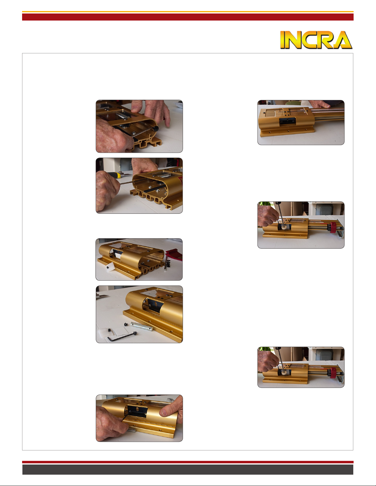
1. Remove the black
nylon arrow clips from
each end of the Base.
(Replacements are provided so don’t worry if
they break.)
2. Use a scratch awl or
small screwdriver to
push out the pivot rod
that secures the red
clamp handle. As the
rod is removed keep an
eye on the small black
washers on either side
of the red clamp handle.
These will need to be replaced later.
3. Remove the 1/8” thick UHMW clamp bearing pad and the
small collection of thin
plastic shims between
the pad
and the metal spring
engager. Retain all for
later re-assembly.
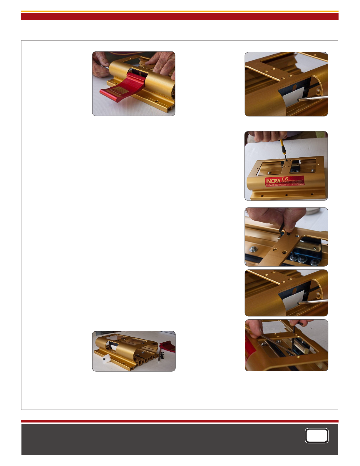
7. Slide your LS Positioner’s Carriage into the
Base. (NOTE: If you are
converting an Imperial
LS Positioner to a Metric
model, make sure you
have already converted
your LS Carriage to the Metric Lead Screw Assembly before
proceeding.) Position the Carriage so that the Base is approximately centered on the Carriage length.
8. Insert the end of the provided Leverage Tool into the
small hole located on the curved side of the LS Base near
the Metal Spring Engager.
9. Push the Leverage Tool
handle so that the nylon
collar bears against the
Metal Spring Engager.
Push and release the tool
a few times to “seat” the
Threaded Segment properly with the Lead Screw on the LS Carriage. Finally, apply
continuous pressure to the Leverage Tool as you tighten the
(2) button head fasteners to secure the Threaded Segment
to the Metal Spring Engager.
4. Using a 1/8” hex key,
unscrew the (2) button
head fasteners located
on either side of the
clamp bearing pad and
remove the existing
Threaded Segment held
by these fasteners.
5. To gain better access for the Threaded Segment replacement, remove the (2) button head fasteners with washers
that secure one of the acrylic view windows and set the
window and fasteners aside.
6. Replace the Threaded Segment previously removed with
the New Threaded
Segment provided.
DO NOT TIGHTEN THE
BUTTON HEAD FASTENERS AT THIS TIME. They
should remain slightly
loose for the next step.
10. Remove the Leverage Tool and slide the LS Carriage from
side to side within the Base to ensure that the threads between the Threaded Segment and the Lead Screw do not
“grind” against one another. If the threads make contact during
the slide, you must adjust the relative position of the Metal
Spring Engager to move the Threaded Segment away from the
Lead Screw as described in Steps 15-18 below. If the threads
do not grind against one another continue with Step 11 below.
11. Replace the thin plastic shims and 1/8” clamping pad removed in Step
4. The thin plastic shims
will slide between the
Metal Spring Engager and
the protruding “fin” on
the LS Base extrusion. (Fig 35 on Pg 15 of your LS Positioner’s Owner’s Manual offers a good illustration of the shim
placement.) The set screw on the 1/8” UHMW clamp bearing
pad should nest into the slotted hole on the Metal Spring
Engager. Make sure to orient the 1/8” clamp bearing pad so
that the surface with the thick tape adhered to it faces the
Metal Spring Engager.
page 1
Manufactured by: Taylor Design Group, Inc. P.O. BOX 810262 Dallas, TX 753 81 w w w . i n c r a . c o m
Page 2
w w w. in c ra .c o m
Threaded Segment Replacement Instruction (Base)
12. Using the 7” long
steel pivot rod, replace
the red clamp handle.
Be sure to place one of
the black nylon washers removed in Step
3 onto the pivot rod
on either side of the
clamp handle. (You
can use a small amount
of grease as an aid to
hold the washer in place.) Hold the clamp handle horozontally pressing it against the UHMW clamp bearing pad as you
advance the pivot rod into the LS Base extrusion, passing
through the first black nylon washer followed by the clamp
handle, the final black nylon washer and into the other end
of the LS Base. Cap off each end of the LS Base extrusion
with the provided black nylon arrow clips. Check that the
operation of the red clamping handle is correct, horizontal
for free sliding movement, midway for micro adjustment and
vertical for full lock. Be sure to test the feel of the unit at
each of these points.
Horizontal = Free sliding, no grinding.
Midway = Able to turn Micro Adjust Knob.
Vertical = Fully locked NO Movement.
If clamping pressure is too tight or too loose, you’ll find
complete instructions on fine tuning your clamping pressure
using the provided shims in your LS Positioner’s Owner’s
manual on beginning at the bottom of Page 14.
13. Carefully slide the LS Carriage out of the Base and re-attach the view window or windows previously removed. If
both view windows were removed, place the one with
the hairline in the opening at the forward end of the base.
(Make sure that the printed hairline is face down.)
If the threads between the Lead Screw in the LS Carriage
and the Threaded Segment in the LS Base make contact
or grind against each other when sliding the Carriage from
position to position, it will be necessary to adjust the Metal
Spring Engager to move the Threaded Segment away from
the Lead Screw. Follow
Steps 15-18 below to
adjust the Metal Spring
Engager’s position.
14. Remove the Red
clamp handle along
with the 1/8” UHMW
clamp bearing pad and plastic shims as described in Steps
1-4 above then carefully slide the LS Carriage out of the
Base.
15. Use a set of Feeler
Gauges (or multiple pieces of the provided plastic
shims, .020”, .010” &
.005” thick) to gauge the
gap between the Metal
Spring Engager and the
vertical “fin” in the LS Base
extrusion. You will need
to DECREASE this gap in
the adjustment process so
it is important to know what the gap is to begin with.
16. Remove both Acrylic
view windows from the
LS Base as well as the
(2) black nylon slotted
head set screws located
between the windows to
gain access to the button head fasteners that
secure the Metal Spring
Engager to the LS Base
extrusion.
17. Using a long 1/8” hex
key, loosen all (4) of the
button head screws. Use
your set of feeler gauges
or the provided plastic
shims as an aid in gauging
the distance as you move
the Metal Spring Engager
assembly closer to the
vertical “fin” on the LS
Base extrusion. Just a
few thousandths should
be all that is required
to create the necessary
clearance (one of the
thinnest shims). Tighten
all (4) button head fasteners. Carefully slide the
LS Carriage back into the
Base to check for clearance between the Lead
Screw and the Threaded
Segment and fine tune as
necessary. Once clearance is achieved, thread
the black nylon slotted
head set screws into the
holes located between the view window openings on the
LS Base. Screw the set screws down until just before they
make contact with the top of the LS Carriage. Now continue
re-assembly beginning with Step 11.
Photography: Grahame Waterson
Manufactured by:
Taylor Design Group, Inc.
P.O. BOX 8102 62 Dallas, TX 753 81
www.in c ra .co m
page 2
INCRA is a Registered Trademark of Taylor Design Group
©2010 Taylor Design Group, Inc.
INCR A Tools are pro tect ed by one o r more o f the f ollowing U S pate nts:
#4, 793, 604, #4 ,93 0,2 21, #5 ,195,73 0, #5 ,275,074 , #5, 423 ,360, # 5,716, 04 5, #6 ,23 7,457,
#6,5 57,601, #6,67 2,190. Other p aten ts gr ante d or pen ding. rev.03 .10.2010
MADE IN THE
USA
 Loading...