

Page 1
PRO
Fence System
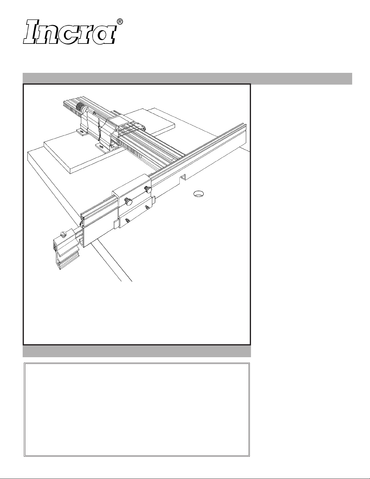
Mounted to your INCRA JIG, the
INCRA PRO Fence System provides
a solid, smooth, and flat guide surface
for the various cutting operations in
your shop. A top-mounted sliding
scale and INCRA’s patented sawtoothed racks provide the means for
easy and extremely accurate stopped
cut setups using the INCRA Stop.
Coupled with the added convenience
and function of a self-storing Stop
Extender Bar with its own sliding
scale and variable stop, the INCRA
PRO Fence System will add new
dimensions to your abilities in the
wood shop.
WARRANTY
Taylor Design Group, Inc. warrants this product for one year from date of purchase. We
will repair, without charge, any defects due to faulty material or workmanship, or at our
option, replace the product free. Please return the failing part only, transportation prepaid,
along with a description of the problem to the address on the back of this manual.
LIFETIME WARRANTY ON POSITIONING RACKS
If an INCRA positioning rack in this tool becomes damaged for any reason, Taylor Design
Group will replace it free of charge for as long as you own the tool. Return the damaged
rack, transportation prepaid, and allow 1 to 2 weeks for delivery.
NOTE: Replacements cannot be sent unless damaged racks have been received
by Taylor Design.
Please be sure to
read this Owner’s
Manual before use
and keep it at hand
for future reference.
SAFETY
Important safety instructions
for using the INCRA PRO Fence
System
■ Before using the INCRA PRO Fence
System, read and follow all of the
instructions and safety information in
this manual.
■ When using the INCRA PRO Fence
System in conjunction with any
other tool, first read and follow all
instructions and safety information in
that tool’s owner’s manual.
■ Use appropriate safety devices.
Keep hands clear of the bit or blade.
Always use a push stick, rubber
soled push block or other safety
devices to keep your hands safely
away from the cutting tool.
■ Never let any part of the INCRA
PRO Fence System interfere with
another tool’s safety guards or other
safety equipment.
■ Never let the bit or blade come into
contact with the aluminum body of
the INCRA PRO Fence, INCRA Stop
or Stop Extender Bar.
■ Always turn off the power and
make sure that the bit or blade is
fully stationary before changing the
setting of any part of the INCRA
PRO Fence, INCRA Stop or Stop
Extender Bar.
■ Wear safety glasses, hearing
protection and follow all normal shop
safety practices.
■ When using negative fence settings
in which the bit is partially recessed
in the fence notch, always insure
that the bit is centered within the
notch.
■ Do not use any router bit with a
diameter greater than 3⁄4" without
first mounting a wooden auxiliary
fence as detailed on page 8.
■ When using the Stop Extender
Bar, make sure that it is securely
fastened to the fence with the
supplied mounting hardware. When
not in use, store the Extender
Bar inside the upper T-slot on the
Fence and secure in place with the
supplied hardware.
Page 2
Parts List
28" INCRA PRO FENCE SYSTEM
Fence Assembly
1 ea. 28" INCRA Pro Fence
1 ea. 16" long, 1⁄32" ruled scale
4 ea. 1⁄32" INCRA rack (6" length)
8 ea. #8
8 ea. #8
2 ea. #10
2 ea. #10
–
32 x 3⁄8" phillips pan head screw
–
32 hex nut
–
32 x 1⁄2" phillips pan head screw
–
32 rectangular nut
2 ea. 5⁄8" o.d. x 1⁄32" thick flat washer
2 ea. 5⁄8" o.d. x 1⁄16" thick gold anodized flat washer
INCRA Stop Assembly
1 ea. INCRA Stop
1 ea. 1⁄32" INCRA rack (4" length)
18" INCRA PRO
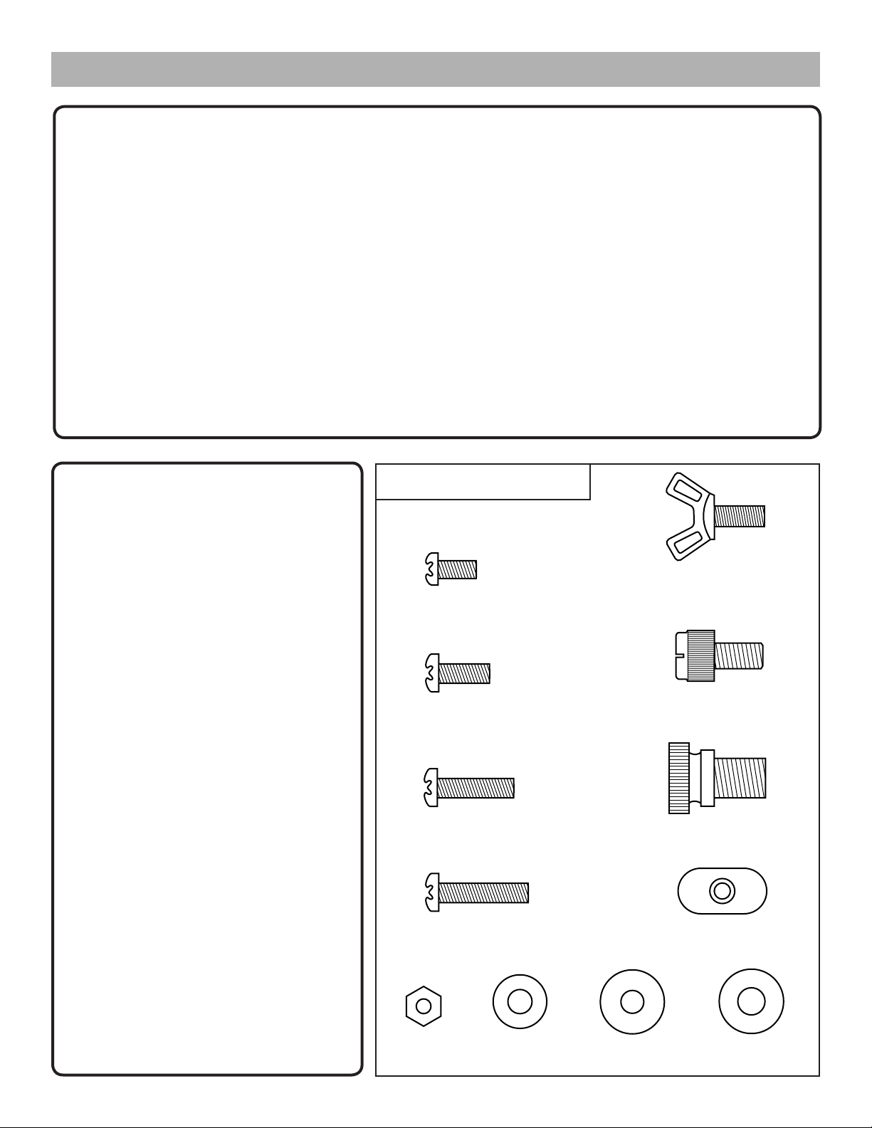
Fasteners – 1:1 scale drawings
FENCE SYSTEM
Fence Assembly
1 ea. 18" INCRA PRO Fence
1 ea. Fence mounting bracket
1 ea. 16" long, 1⁄32" ruled scale
3 ea. 1⁄32" INCRA rack (6" length)
8 ea. #8
8 ea. #8
2 ea. #10
4 ea. #10
2 ea. #10 flat washer
2 ea. 5⁄8" o.d. x 1⁄32" thick flat washer
2 ea. 5⁄8" o.d. x 1⁄16" thick gold anodized
flat washer
2 ea. #10
2 ea. #10
–
32 x 3⁄8" phillips pan head screw
–
32 hex nut
–
32 x 1⁄2" phillips pan head screw
–
32 rectangular nut
–
32 x 3⁄4" phillips pan head screw
–
32 x 7⁄8" phillips pan head screw
#8 – 32 x 3⁄8"
phillips pan head screw
#10 – 32 x 1⁄2"
phillips pan head screw
#8 – 32 x 3⁄4"
phillips pan head screw
2 ea. 1⁄4"
2 ea. 3⁄8"
2 ea. #8
2 ea. #8
–
20 x 1⁄2" nylon thumbscrew
–
16 x 1⁄2" nylon thumbscrew
–
32 x 3⁄8" phillips pan head screw
–
32 hex nut
1 ea. Plastic stop strip (black) 3⁄4" x 5"
Stop Extender Assembly
1 ea. 28" Extender Bar
1 ea. #10
1 ea. 5⁄8" o.d. nylon washer
1 ea. #10
1 ea. 16" long, 1⁄32" ruled scale
1 ea. Extender Bar Stop
1 ea. 1⁄4"
–
32 x 1⁄2" thumbscrew
–
32 rectangular nut
–
20 x 1⁄2" nylon thumbscrew
#10 – 32 x 1⁄2" Thumbscrew
1
⁄4 – 20 x 1⁄2" nylon thumbscrew
3
⁄8 – 16 x 1⁄2" nylon thumbscrew
INCRA Stop Assembly
(Same as in the 28" INCRA PRO Fence System)
Stop Extender Assembly
1 ea. 18" Extender Bar
1 ea. #10
1 ea. 5⁄8" o.d. nylon washer
1 ea. #10
1 ea. 16" long, 1⁄32" ruled scale
1 ea. Extender Bar Stop
1 ea. 1⁄4"
–
32 x 1⁄2" thumbscrew
–
32 rectangular nut
–
20 x 1⁄2" nylon thumbscrew
#8 – 32 x 7⁄8"
phillips pan head screw
#8 – 32
hex nut
2
#10 SAE
flat washer
#10 – 32 rectangular nut
5
⁄8" o.d. x 1⁄16"
thick gold flat washer
5
⁄8" o.d. x 1⁄32"
thick flat washer
Page 3
Assembly
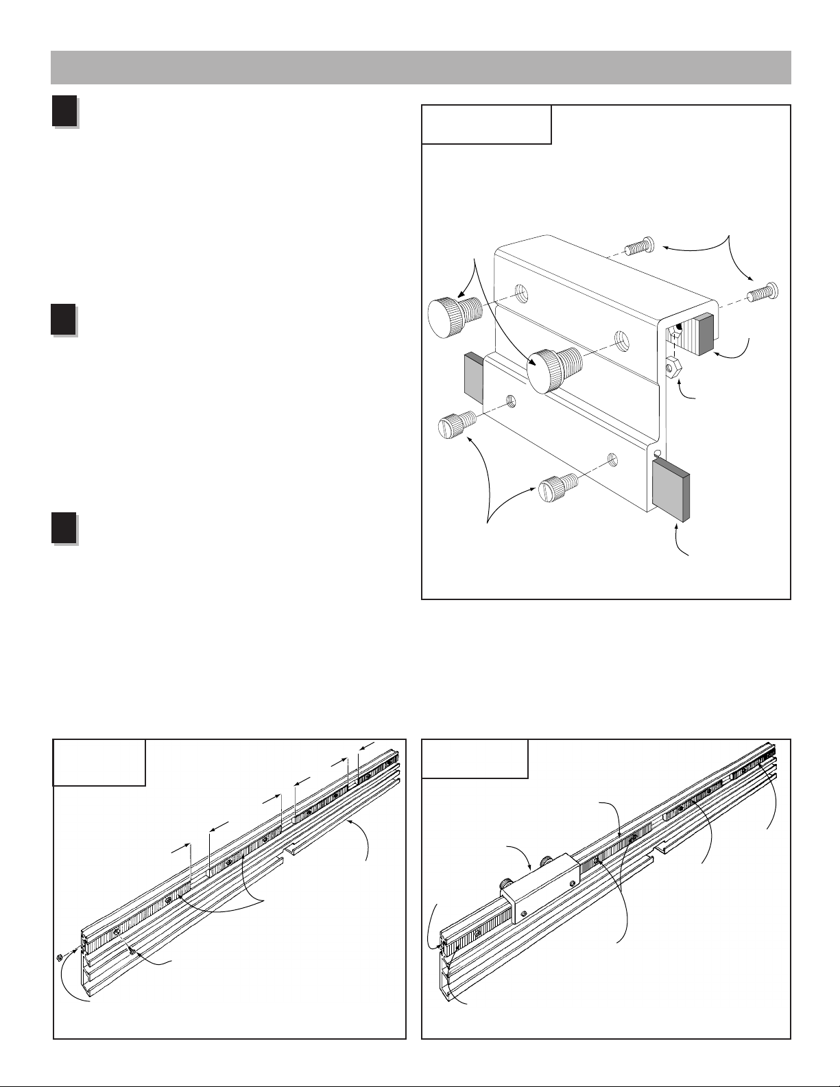
Assemble the INCRA Stop
1
Using the (2) #8
and #8
–
32 hex nuts, fasten the 4" long blue INCRA
–
32 x 3⁄8" phillips pan head screws
rack to the INCRA Stop and tighten the screws. See Fig.
1. Slide the 3⁄4" x 5" plastic strip into the slot in the stop
and secure with (2) 1⁄4"
Thread the (2) 3⁄8"
–
20 x 1⁄2" nylon thumbscrews.
–
16 x 1⁄2" nylon thumbscrews
into the INCRA Stop as shown. One or both of these
thumbscrews can be used to clamp the INCRA Stop to
the fence. In use, the plastic strip provides a non-metallic
stop surface which can be shaped for special stop setups
and can be micro adjusted by loosening the smaller
thumbscrews.
2
Loosely install the racks in the
INCRA Fence
Insert the #8
the racks as shown in Fig. 2 and loosely attach the
–
#8
32 hex nuts. Slide each of the hex nuts on the racks
into the smaller T-slot in the back of the INCRA Fence.
Position the two outer racks approximately flush with the
ends of the fence with the remaining two racks spaced
about 15⁄16" apart. (For the 18" INCRA PRO Fence,
leave about 1⁄32" between the ends of the racks.) With
the racks loosely installed, you should be able to shift
each rack from side to side easily with your finger.
–
32 x 3⁄8" phillips pan head screws through
FIG. 1
INCRA Stop Assembly
3
/8 – 16 x 1/2"
nylon
thumbscrews
#8 – 32 x 3/8"
phillips pan
head screws
INCRA
rack
#8 – 32 hex nut
3
Tighten the racks on the
INCRA Fence
Begin by tightening the two mounting screws for rack #1,
as shown. Next, clamp the INCRA Stop to your fence
so that it bridges the gap between the ends of racks #1
and #2 (see Fig. 3), and tighten the mounting screws
for rack #2. Now move the INCRA Stop to bridge the
gap between racks #2 and #3 and tighten the mounting
screws for rack #3. Finally, bridge the gap between racks
#3 and #4 and tighten the rack #4 mounting screws. This
process aligns the racks so that the INCRA Stop will
operate accurately along the entire length of the fence.
FIG. 2
Loosely install
fence racks
15⁄16"
15⁄16"
INCRA racks
15⁄16"
28" INCRA PRO Fence
1
/4 – 20 x 1/2"
nylon thumbscrews
FIG. 3
Tighten the racks
Second:
Bridge the gap between
racks #1 and #2 with
the INCRA Stop
Rack #1
Plastic stop strip
Fourth:
Repeat the steps to
tighten racks #3 and #4
Rack #2
Rack #4
Rack #3
#8-
32 x 3/8"
phillips pan head screw
Loosely attach the #8-32 hex nuts to the screws on each
rack then slide the racks in place on the back of the fence
capturing the nuts in this T-slot
Third:
Tighten the rack mounting
screws on rack #2
First:
Tighten this rack’s mounting screws
BEFORE putting on the INCRA Stop
3
Page 4

Mounting the INCRA PRO Fence …
…to the INCRA JIG ULTRA or
ULTRA LITE:
Insert the #10
screws through the thick (gold) washers then through
the holes on the back of the fence mounting bracket.
Place a thin (silver) washer on each screw then loosely
attach the rectangular nut. See Fig. 4. The raised
rim on the rectangular nut should face the mounting
bracket. Now slide the fence onto the thin washer and
rectangular nut so that both are captured in the T-slot
on the back of the fence. Make sure the washer is
captured in the T-slot provided as shown in Detail 4a.
Position the fence so that the carriage is approximately
centered on the fence length and tighten the two
mounting screws.
To achieve a silky smooth carriage motion, it
is important that your table surface be flat and
-smooth, and that the carriage be installed parallel
to it. If you find that your carriage tends to bind slightly
during some portions of its travel, the following
additional step should take care of it. Simply place 3
or 4 pieces of paper under the infeed end of the fence
before tightening the screws in the final step of the
fence mounting procedure described above, and then
remove the paper. If the problem still persists, either
add a few more pieces of paper, or place the paper
under the other end of the fence before tightening.
–
32 x 11⁄8" phillips pan head
FIG. 4
Mounting to your INCRA JIG
ULTRA or ULTRA LITE
Fence
mounting
bracket
INCRA PRO Fence
Detail 4a
Thick (gold)
washer
Thin washer
captured here
#10 - 32 x 11⁄8"
phillips pan
head screw
Thick (gold)
5
⁄8" o.d. flat
Thin (silver)
5
⁄8" o.d. flat
washer
Raised rim on rectangular nut
faces the mounting bracket
washer
…to the INCRA JIG PRO:
Important: Your INCRA JIG PRO must be mounted to
a 3⁄4" plywood base and the cam clamp must be in the
locked position before installing the fence.
Insert the #10
through the thicker (gold) 5⁄8" o.d. flat washer then
through slot “A” (see Fig. 5). While holding the screw
in place, add the thin 5⁄8" o.d. flat washer then thread
on the rectangular nut. The raised rim around the
threaded hole on the nut should face the washer. With
the rectangular nut still loose, slide your INCRA PRO
Fence onto the washer and rectangular nut so that
both are captured in the T-slot in the back of the fence.
Make sure the washer is captured in the slot provided
as shown in Detail 5a. Repeat the above fastener
installation for slot “B”, sliding the fence to capture the
washer and rectangular nut. Position the fence so that
the mounting bracket is centered on the length of the
fence and securely tighten the two machine screws.
–
32 x 1⁄2" phillips pan head screw
FIG. 5
Mounting to your
INCRA JIG PRO
INCRA PRO Fence
4
Slot “A”
Detail 5a
Thick washer
Thin washer
captured here
Rectangular nut
Thin 5⁄8" o.d.
flat washer
Thick
(gold)
5
⁄8" o.d.
flat
washer
Slot “B”
#10 - 32 x 1⁄2"
phillips pan
head screw
Page 5

…to the Original INCRA JIG:
Note: Only the 18" INCRA PRO Fence can be
mounted to the Original INCRA JIG.
Important: Your Original INCRA JIG must be mounted
to a 3⁄4" plywood base and the black clamping knob
must be fully tightened before installing the fence.
Attach the fence mounting bracket supplied with
your 18" INCRA PRO Fence to the front end of your
Original INCRA JIG using the two #10
pan head screws, #10 flat washers and rectangular
nuts as shown in Fig 6. The “L” feature on the fence
mounting bracket should rest on the top of your INCRA
JIG as shown in Detail 6a.
–
32 x 3⁄4" phillips
FIG. 6
Attach fence
mounting bracket
#10 flat
washer
#10 – 32 x 3/4"
phillips pan
head screw
Detail 6a
“L” feature
Fence mounting bracket
Rectangular nuts
Top of
INCRA
Jig
Insert the #10
–
32 x 7⁄8" phillips pan head screw
through the thicker (gold) 5⁄8" o.d. flat washer, then
through hole “A” (see Fig. 7) on the fence mounting
bracket. While holding the screw in place, add the thin
5
⁄8" o.d. flat washer then thread on the rectangular nut.
FIG. 7
Mounting to your
INCRA JIG
The raised rim around the threaded hole on the nut
should face the washer. With the rectangular nut still
loose, slide your INCRA PRO Fence onto the washer
and rectangular nut so that both are captured in the
T-slot in the back of the fence. Make sure the washer
is captured in the slot provided as shown in Detail
7a. Repeat the above fastener installation for hole “B”,
sliding the fence to capture the washer and rectangular
nut. Position the fence so that the mounting bracket
is centered on the length of the fence and securely
tighten the two machine screws.
Adjusting the Fence Angle
#10-32 x 7⁄8"
phillips pan head screws
Fence
mounting
bracket
Hole “A”
Detail 7a
Thick (gold) washer
Thin washer
captured here
Rectangular nut
Thin (silver)
5
⁄8" o.d. flat washer
Thick
(gold)
5
⁄8" o.d.
flat
washer
Hole “B”
After mounting the INCRA PRO Fence, clamp
your INCRA Jig to the stationary tool of your
choice and with the INCRA Jig set to midrange, check the angle of your fence to the
table using a machinist’s or carpenter’s square.
Sometimes, as a result of the plywood base
not being perfectly flat, the angle may be
slightly more or less than 90°. To correct the
angle, place a masking tape shim along the
length of the mounting bracket between the
bracket and the fence as shown in Fig. 8.
FIG. 8
Adjusting the
fence angle
Table top
5
Place shim here if angle
is greater than 90°
90°
Place shim here if angle
is less than 90°
Page 6

Installing the Extender Bar
Fig.9 shows the proper placement for your Stop
Extender Bar. Insert the Extender Bar with the scale
facing the front of the fence, then slide the bar in the
T-slot until the ends are flush and lock in place using
the supplied #10
–
32 x 1⁄2" thumbscrew, 5⁄ 8" o.d. nylon
washer and rectangular nut as shown.
A second Stop Extender Bar can be purchased
should you want to increase the stop range beyond both
ends of your INCRA PRO Fence.
CAUTION: Always install the Extender Bar in the UPPER
T-slot, never the lower one.
Extender Bar Stop
Position the Extender Bar about 2" beyond the fence end
and using the supplied 1⁄4"
attach the Extender Bar Stop. See Fig. 10. The Stop can
be used on either end of the Extender Bar to increase
your stop range beyond the ends of the INCRA PRO
Fence. When not in use, the Stop can be turned around
and locked to the Extender Bar (see Fig. 11). This storage
position places the Stop out of the way, leaving the front
face of the INCRA PRO Fence uninterrupted for through
cut operations.
–
20 x 1⁄2" nylon thumbscrew,
FIG. 9
Extender bar
#10 – 32 x 1⁄2"
thumbscrew
5
⁄8" o.d.
nylon washer
Front face of fence
Extender bar
Rectangular nut
FIG. 10
Extender Bar Stop
1
⁄4" – 20 x 1⁄2"
nylon thumbscrew
Extender Bar Stop
Applications
INCRA Stop
When used in conjunction with your new INCRA PRO
Fence, the INCRA Stop provides the same precise rack
positioning capabilities that your INCRA Jig offers. The
sliding scale in the top of your fence becomes a versatile
reference for use in setting stop positions at the router
table and the drill press. The sliding plastic stop strip
on the INCRA Stop permits micro-adjusting of the stop
positions between 1⁄32" steps. The Stop can function
on either the outfeed or infeed end of the fence with any
thickness of stock, even rabbeted boards. Two INCRA
Stops can work together at opposite ends of the fence for
many advanced operations, such as multiple mortises and
slots.
FIG. 11
Extender Bar Stop
storage position
FIG. 12
INCRA Stop
6
Page 7

Zeroing the INCRA Stop to
the End of a Board
For most applications, you will be using your
INCRA Stop on the outfeed end of the INCRA
Fence to control the length of a cut relative to
the front end of the board. Here is how to set
the initial scale position for this type of setup:
After installing the bit you wish to use,
set the fence to bit distance at about 1".
1
Place a square cut piece of scrap stock
against the fence with the end of the board
against the infeed side of the bit. Turn the bit to
find the high spot.
FIG. 13
Top view of
stop setup
INCRA
Stop
First:
Slide the board
up to contact
the “high spot”
on the bit
Next, lock the INCRA Stop to the fence on
the outfeed side of the bit with the plastic
2
stop strip as close as possible to the end
of the board. Adjust the position of the stop
strip until both the strip and the bit contact the
end of the board. See Fig. 13.
You now have the choice of setting
the sliding scale to one of three initial
3
positions:
In most cases, you will simply slide the
A
scale to align the 0" mark on the scale
with the end of the INCRA Stop nearest the
bit. When set to this initial position, the scale
reading at any subsequent INCRA Stop location
will give you a direct readout of the total length
of the cut. (See Dimension “A”, Fig. 14.)
If you wish the subsequent scale readings
B
to reflect the distance from the front end of
the board to the center of the cut (Dimension
“B”, Fig. 14), slide the scale to an initial reading
under the end of the INCRA Stop equal to
minus one half of the bit diameter. Example:
If you are using a 1⁄2" diameter bit, complete
Steps 1 and 2 above then slide the scale to
read negative 1⁄4".
If you want the scale reading for future
C
INCRA Stop locations to reflect the
distance between the end of the board and the
outfeed edge of the cutter (Dimension “C”, Fig.
14), then slide the scale to an initial reading
equal to minus the bit diameter.
Dual INCRA Stop
Operations
Using the same setup process described above
and a second
precise positioning of mortises on a board quite
simple. The INCRA Jig Projects and Techniques
book covers this technique fully and includes
several unique projects which feature dual
INCRA Stop operations.
INCRA Stop
, you will find the
Second:
Lock the INCRA Stop to the
fence and adjust the position
of the plastic stop strip to
contact the end of the board
Third:
Slide the scale to read one of
the initial scale settings as
described in Fig. 14 below
FIG. 14
Initial scale
setting
FIG. 15
Dual stop
operations
A
A
A
A
B
C
A
-A.
A
Slide scale to 0" for a direct readout of Dimension “A”
B.
Slide scale to “minus 1/2 of the bit diameter” for a direct
A
readout of Dimension “B”
-C.
Slide scale to “minus diameter of the bit” for a direct
readout of Dimension “C”
7
Page 8

X-Y Positioner for the Drill Press
Used at your drill press, your new INCRA Jig and INCRA
PRO Fence System are the ultimate in X-Y positioning
control. You can quickly and accurately locate and drill
any pattern of holes by simply moving the INCRA Jig
and the INCRA Stop to the desired settings. A cribbage
board is a good example of a project that requires this
ability. And since you can locate any hole to within a few
thousandths of an inch, you will find this technique great
for making perfect dowel joints.
Mounting an Auxiliary Fence to
Your INCRA PRO Fence
If you should desire to use a router bit with a diameter
greater than 3⁄4", you must first mount a wooden auxiliary
fence to your INCRA PRO Fence. The following
information should help in determining the dimensions of
the auxiliary fence, see Fig. 17.
Thickness (A): The thickness of the auxiliary fence should
be 11⁄2 times the diameter of the router bit you plan to use.
(Example: To use a 1" diameter router bit, your auxiliary
fence should be 11⁄2" thick.)
Height (B): The height of the auxiliary fence should be 3"
minimum.
Length (C): Cut the length of the auxiliary fence to match
the length of your INCRA PRO Fence, either 18" or 28".
Fence Notch Width (D): At least 1⁄4" greater than the
diameter of the router bit.
Fence Notch Height (E): At least 1⁄4" greater than the
maximum depth of cut you plan to use with the router bit.
To mount the auxiliary fence to your INCRA PRO
Fence, you will need (2) #8
flat washers and (2) #8
machine screws should be slightly less than the thickness
of the auxiliary fence. Drill two 3⁄16" dia. through holes
in the auxiliary fence in the locations shown in Fig. 18.
Now, using a 1⁄2" diameter drill bit, counterbore the hole
locations.
Note: Adjust the depth of the counterbore so that the
screw, when installed in the counter bore with the #8 flat
washer, extends slightly less than 3⁄4" through the back of
the auxiliary fence. Loosely attach the #8
the screws then slide the hex nuts into the T-slot located
on the front face of the INCRA PRO Fence. Tighten the
machine screws to secure the auxiliary fence in place.
FIG. 18
Hole/Counterbore locations
–
32 machine screws, (2) #8
–
32 hex nuts. The length of the
–
32 hex nuts to
3
⁄16" dia. through hole,
1
⁄2" dia. counterbore
(See Note above for
counterbore depth)
FIG. 16
X-Y Positioning at
the drill press
FIG. 17
Auxiliary fence
D
E
C
B
A
For short term auxiliary fence applications, you
might find it convenient to use an aggressive
double-faced tape to attach the auxiliary fence. We
recommend #ST501 manufactured by SpecTape of Texas.
Call 1-800-442-1338 for your nearest distributor, or check
with your INCRA dealer. Do not use standard double-faced
carpet tape.
41⁄2"
21⁄32"
Made in America by: TAYLOR DESIGN GROUP, INC. P.O. BOX 810262------Dallas, TX 75381
Printed in the U.S.A. © 1993, Taylor Design Group, Inc. INCRA is a registered trademark of Taylor Design Group, Inc. RV02-97
18" Fence
7" 14"9"
21⁄32"
8
28" Fence
 Loading...