

Page 1
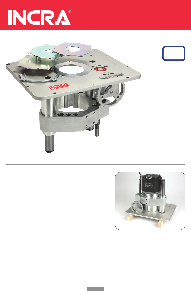
PRL-V2 Precision Router Lift
By Woodpeckers
MADE IN THE
USA
SAFETY
Always unplug your router motor
before making any adjustments
to the router lift.
Refer to your router’s owner’s
manual for specific safe
operation instructions.
INSTALLING A PC-7518 ROUTER MOTOR
Set the lift face down in the opening of your router table.
Alternatively, you can set it on two spacers at least 1” thick.
Make sure the lift carriage is set as close to the plate as
possible (approximately 2-1/4”). If the carriage requires
coarse adjustment, jump ahead to the section on using the
Lift Wrench on page 3, then return here once the carriage
has been moved up against the gear box.
Ensure the four (4) clamp screws are loose enough to allow for the motor to be inserted. Next,
carefully insert the motor until the motor contacts the plate. Rotate the motor so that the cord and
speed adjustment are clear of the posts. Make sure no part of the router interferes with the lift.
Make sure that none of the motor pins are being clamped by the pads.
Now tighten the clamp screws. Only three are accessible at this point. Flip the lift right side up
and set it into the table opening. Use the lift wrench to lower the carriage a couple of inches. Now
tighten the fourth screw.
page 1page 4
Page 2
w w w . i n cr a . c o m
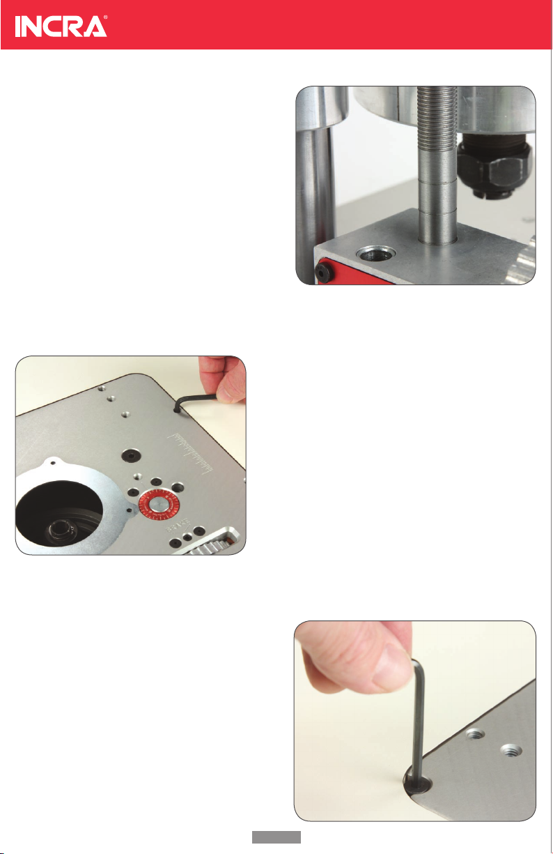
SETTING THE FINE ADJUSTMENT
LIFT ROD
The thumb wheel allows for a total of 3/4” of fine
adjustment. It’s helpful to start out in the middle of
this range. Take a look at the lift rod. You’ll notice
three grooves spaced 3/8” apart. The three grooves
represent the beginning, middle, and end of travel.
Use the thumb wheel to adjust the lift rod to the
middle groove which is the middle of the adjust-
ment range. It may be necessary to adjust the lift
rod to see all three grooves.
SETTING THE PLATE FLUSH
The (10) threaded holes around the perimeter of the
plate are for access to the leveling screws mounted
into your INCRA Router Table. Insert the supplied
5/32” hex key through these holes to adjust. If you
have purchased the PRL-V2 for use in other (non-
Incra) router tables, insert the included set screws
into the threaded holes for leveling.
LOCKING THE PRL-V2 IN YOUR
TABLE RECESS
Lift the PRL-V2 from your router table recess and
thread the included socket head cam screw into
the hole located at the corner of the plate. Thread
the fastener in until the top of the screw is just
below the top of the plate. Carefully lower the
PRL-V2 back into the router table, making sure the
cam screw is rotated to clear the opening in your
table top. Turn the fastener clockwise to lock the
PRL-V2 in your table.
Page 3

USING THE LIFT WRENCH
To use the lift wrench, orient the black grip so that it is
parallel to the front edge of the plate with the flat side
pointing to the left. Insert the wrench (compressing the
spring) until it bottoms out in the carriage. As you rotate
the wrench in either direction, the locking mechanism will
release, allowing the router to be raised or lowered.
Once the router is near the desired position (within 3/8”
or less), re-orient the wrench handle to the original posi-
tion, pointing left and parallel with the front edge of the
plate. This will lock the motor in place and allow for fine
tuning with the thumb wheel.
NOTE: The wrench comes pre-assembled with an assist spring.
This spring is rated to lift most of the weight of the PC-7518 mo-
tor. The spring eliminates the need to hold down the plate while
making course adjustments. The spring can be easily removed by
simply loosening the small set screw in the white plastic foot.
PRL-V2 Precision Router Lift
By Woodpeckers
The PRL-V2 also features a brake. For most routers, the
brake isn’t necessary. However if you experience vibra-
tion while routing, the brake will prevent the bit height
from changing on its own. A 1/8” hex key is supplied for
the brake. DO NOT OVER TIGHTEN THE BRAKE. A little
pressure is all that is required.
In spite of having a brake, it is imperative to make sure
the vibration isn’t being caused by dirt, dust or rust on
the router bit shank, collet or collet taper. Make sure
these surfaces are completely clean. Apply a small amount of light machine oil to the inside of the
taper before re-assembly. . Run-out typically causes vibration and can lead to premature router bit
failure.
page 3page 2
Page 4

Taylor Design Group, Inc.
P.O. BOX 810262 Dallas, T X 7538 1
w w w. i n c r a .c o m
INC RA is a Re giste red Tradema rk of Ta ylo r De sign Grou p
©20 08 Tayl or Des ign Gr oup, In c.
INC RA Too ls are pro tecte d by one or m ore of the fo llow ing US pat ents : # 4,79 3,60 4, #4 ,93 0,22 1,
#5 ,195,73 0, #5 ,275, 074, # 5,4 23,36 0, # 5,716,0 45, # 6,23 7,45 7, #6 ,557,6 01, #6 ,672 ,190. Ot her
pat ents g rante d or pe ndin g. rev. 09.25 .08
CHANGING MAGNA-LOCK RING
To remove the ring insert, slide the included 3/32”
hex key into the access hole and lift up. When
inserting the new ring, orient the plate so that the
access hole feature on both the PRL-V2 and the
Magna-Lock ring are aligned and carefully lower the
ring into the recess. TIP: The Magna-Lock ring is
keyed to fit only one way. If it doesn’t align on the
first try, flip it over and try again.
CHANGING BITS
First remove the Magna-Lock ring. Now use the
lift wrench to raise the router collet completely
above the plate. Use the wrenches supplied
with your router to change the bit.
MICRO-ADJUSTING
The thumb wheel permits easy fine adjustments to
your depth of cut without any special tools. Rotat-
ing the thumb wheel to the left raises the router bit;
rotating to the right lowers the bit.
The red micro adjust scale disc behind the thumb
wheel can be zeroed to any position. It is typically
set to zero once the router bit is at the desired
height. Then you can easily make a specific, fine
adjustment with the thumb wheel while the scale tracks the movement. The scale is adjusted by
rotating the knurled disc in either direction using your finger.
 Loading...