

Page 1
w w w. i n c r a . c o m
Instructions
Safety
Before using the INCRA Miter V120, read and follow all of the instructions
and safety information in this document.
• When using the INCRA Miter V120
in conjunction with any other tool,
first read and follow all instruc tions and safety information in
that tool’s owner’s manual.
• When using the INCRA Miter V120,
always keep your hands clear of
the cutter and the line of cut.
• Always turn off the power and
make sure that the cutter comes
to a comp lete s top be fore
changi ng the setting of any part
of the I NCRA Miter V120.
Adjust the Miter Bar for a Perfect Fit in Your Miter Channel
1
Place the Miter V120 in you r tool’s Miter Chann el. NOTE: I f the M iter
Channel does not have a T-slot, remove and save the Retaining T-Clip and
screw located at the end of the miter bar as shown in Figure 1. Screw the
large clamping knob with washer
through the protractor into the
miter bar.
Miter Bar
Retaining T-Clip
2
Using the supplied 3/32” hex key, adjust each of the (3) visible miter bar
expansion disks for a zero-sideplay, sliding fit in your Miter Channel as
shown in Figure 2. Turning the
fastener clockwise EXPANDS the
bar width. The disks are designed
to require a fair amount of
adjustment torque for proper
expansion.
3
/
32
” Hex Key
Expansion Disks
• Always securely tighten the large
black clamping knob before
starting any cut.
• Wear safety glasses, hearing pro tection, and follow all normal
shop safety practices.
• After making any adjustments to
the miter angle of your INCR A
Miter V120, always verify safe
clearance between the cutter and
all parts of the INCR A Miter V120,
and its attachments.
Setup
Fig. 1
Fig. 2
Square Miter Faceplate to your Application
(table saw, router table, etc.)
4
Caution: Always unplug the power tool before squaring the faceplate
to your application. Loosen both the large and the small clamping knobs.
Set the indexing tooth to 0 degrees, and tighten the small clamping knob,
then tighten the large clamping knob. See Figure 4.
Large
Fig. 4
Clamping Knob
Indexing Tooth
Set at 0°
Small
Clamping Knob
5
Using the supplied 1/8” hex key, loosen the (4) button head fasteners
that secure the faceplate to the protractor and, depending on your application, square the faceplate to the blade, miter slot, sanding belt, etc. NOTE:
When squaring to a saw blade (see Figure 5), use a reliable square for this
important alignment. Securely retighten the (4) button head fasteners to
complete the alignment.
This important one-time adjustment prepares your INCRA Miter
V120 for perfect angles at all other
indexing tooth positions. Verify
the accuracy of your alignment
with a test cut, and re-align if the
cut is not exactly 90 degrees.
Fine adjustments to the angle of
the fence mounting bracket to
your table top can also be made by loosening the same fasteners and placing a paper shim between the bracket and the underside of the protractor.
Fig. 5
Operation
You r INC R A Miter V120 is now read y to e asi ly an d accurat ely pro duce
perfect angles. Just loosen both clamping knobs and engage the indexing
tooth at the desired angle. Lock the indexing tooth clamping knob (the
small knob), then lock the large clamping knob.
Adding a Wooden Auxiliary Fence
Your INCRA Miter V120’s vertical faceplate doubles as a Universal Mounting
Bracket that makes it easy to attach your own user-made auxiliar y fence if
you ever need one. Just cut a straight piece of wood to the desired length
(18” to 24” is a good size),
and at ta ch with u ser supplied
wood screws and washers through
the two slot ted holes.
See Figure 6.
Wooden Auxiliary
Fence
Fig. 6
3
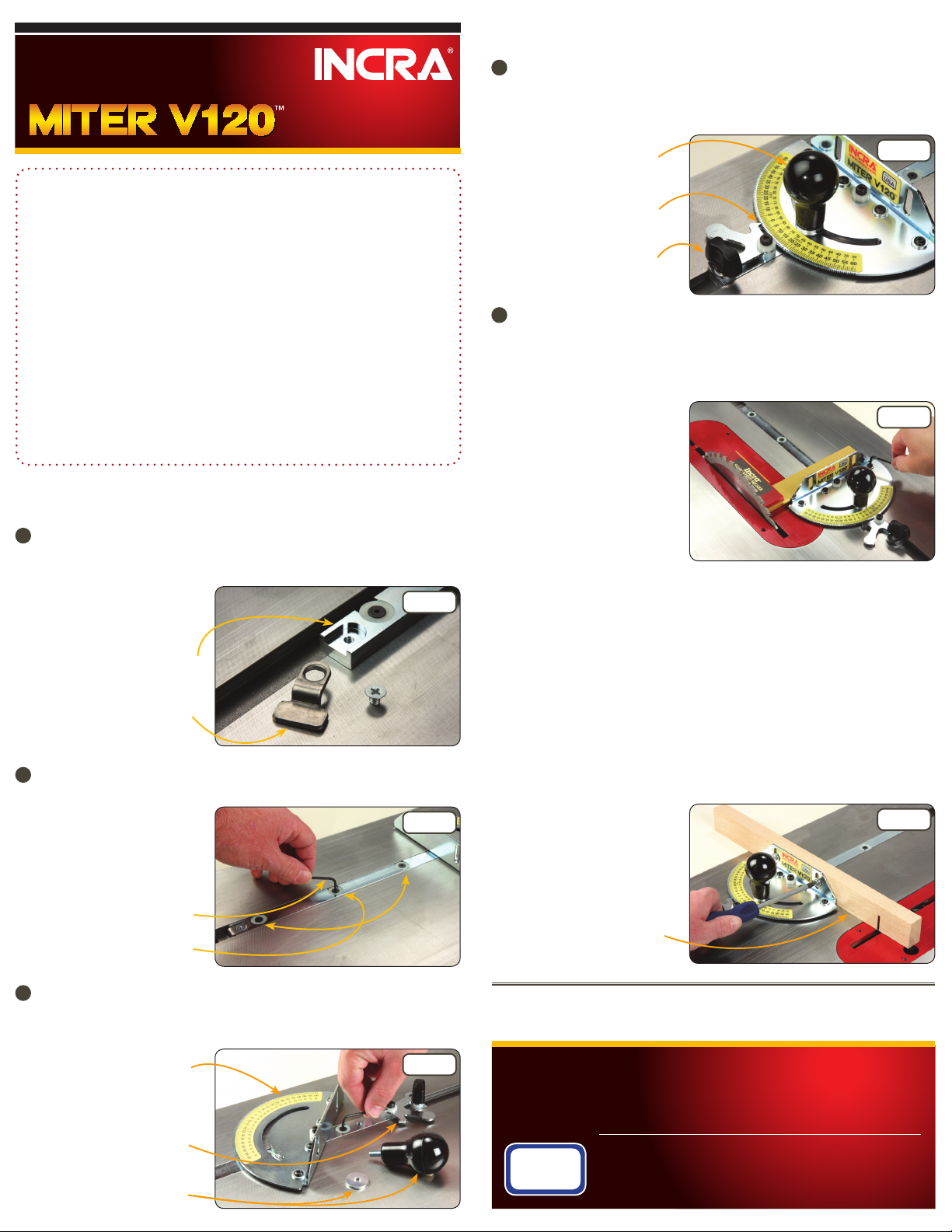
Remove the large clamping knob and disengage the indexing tooth from
the protractor. Pivot the protractor head to access and adjust the fourth
expansion point. See Figure 3. Replace the large clamping knob and washer.
Protractor Head
Fig. 3
Indexing Tooth
Large Clamping
Knob and Washer
Visit our website at www.incra.com for miter accessories along wit h
many other exciting and practical incremental woodworking tools.
INCRA - MAKING ACCURACY EASY!
Manu factured b y:
Taylor Design Group
P.O.B OX 810262 Dallas, T X 75381
MADE IN THE
USA
INCR A Tools are protect ed by one or more of the foll owin g
US pat ents : #4,793,60 4, #4,930, 221, #5,195,73 0, #5, 275,074, #5,423 ,360,
#5,716,0 45, #6,237,45 7, #6,557,601, #6,672 ,190. Other pat ents gran ted
or pen ding. INC RA is a Re gis tered Trademark of Tayl or Des ign G roup,
Inc. © 20 08 Tay lor Desig n Group, Inc. Rev.10.01.08
 Loading...