

Page 1
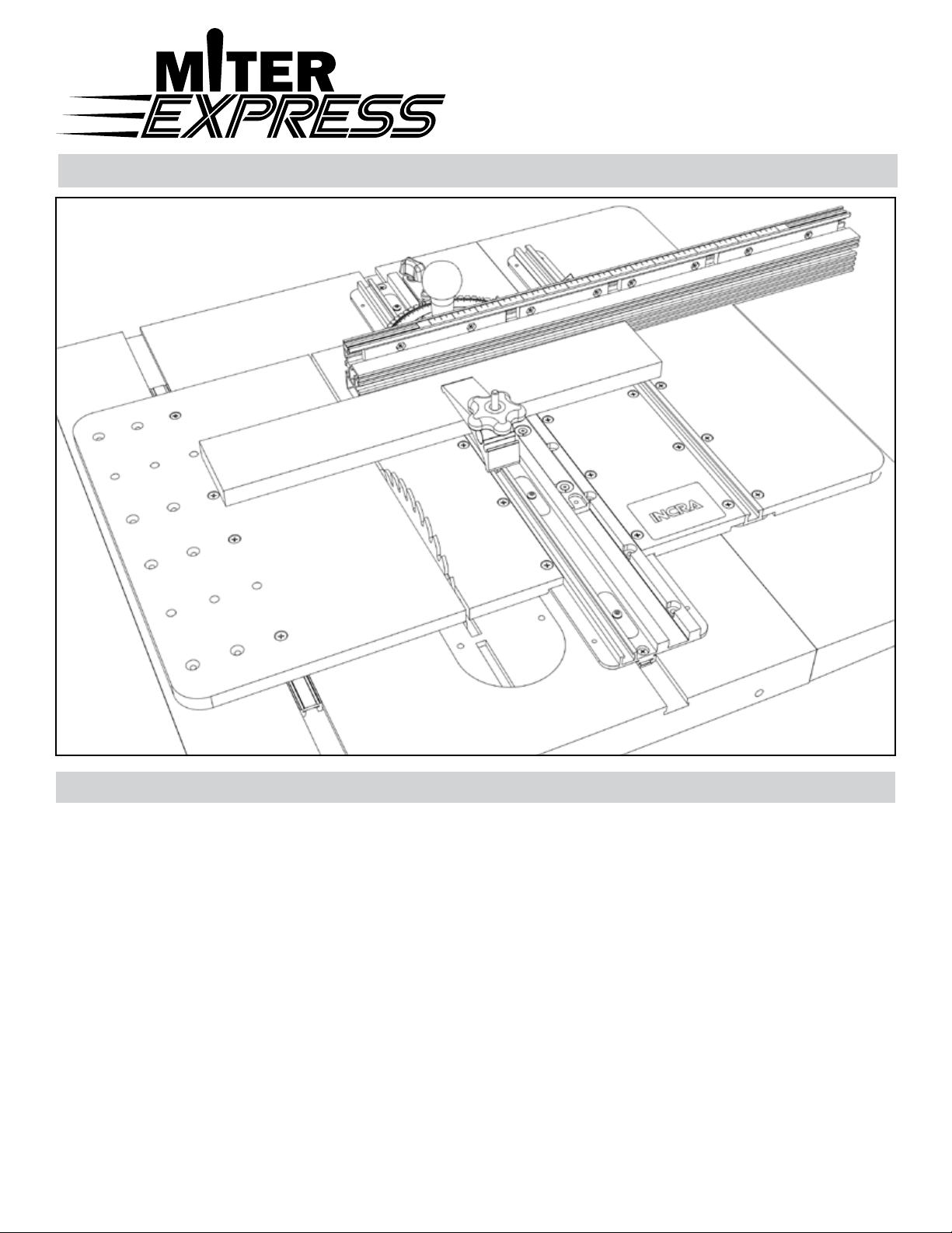
Upgrades your miter gauge to a sled for increased accuracy,
control and safety on work pieces large and small.
Owner’s Manual
Owner’s Manual
Miter gauge not included.
Another innovation in precision from INCRA
®
saFeTY
saFeTY
Important safety instructions for using the INCRA Miter Express
■ Before using the INCRA Miter Express, read and
follow all of the instructions and safety information in
this owner’s manual.
■ When using the INCRA Miter Express in conjunction
with any other tool, rst read and follow all instructions
and safety information in that tool’s owner’s manual.
■ Never let the saw blade come in contact with the
aluminum or steel components of the INCRA Miter
Express.
■ Before making any cut, always make sure that the
INCRA Miter Express cutoff drop panel is locked
securely in the miter slot.
■ When using the INCRA Miter Express, always keep
your hands clear of the saw blade and the line of cut.
■ Always turn off the power and make sure that the saw
blade comes to a complete stop before changing the
setting of any part of the INCRA Miter Express.
■ Always securely tighten your miter gauge’s clamping
knob before starting any cut.
■ Wear safety glasses, hearing protection, and follow all
normal shop safety practices.
■ After making any adjustments to the miter angle or
fence position of your miter gauge, always verify safe
clearance between the blade and fence before turning
on the saw.
■ After making any adjustments to the fence position on
the INCRA Miter Express, always make sure that all
knobs and fasteners on the fence mounting bracket
and the outboard fence lock are securely tightened.
■ When using a stop to position a piece for a cut, always
hold or otherwise clamp the board between the stop
and the blade.
■ Always make sure the arrows on the Miter Express
caution label point toward the table saw blade.
Page 2
ParTs lIsT
ParTs lIsT
Carefully Unpack Components
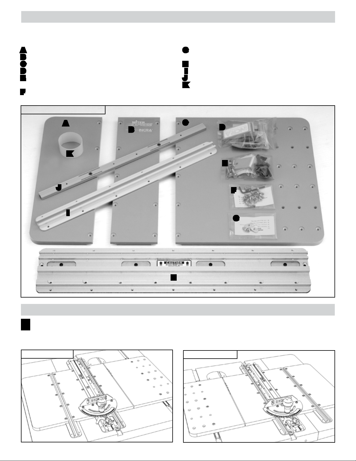
After carefully unpacking all components, check the contents against the photo in Fig. 1 and parts list below.
A Small Miter Express Panel w/rounded corners
B Small Miter Express Panel w/square corners
C Large Miter Express Panel
D Hold Down Clamp
E Hardware Pack C-15 (Outboard Fence Support and
Fasteners)
F Hardware Pack C-13 (Panel Assembly Fasteners and
Hex Keys)
FIG. 1 Miter Express Components
A
B
K
J
I
G Hardware Pack C-14 (T-Slot Retainers and Cam
Screws)
H Utility Plate
I Panel Connector
J Aluminum Miter Bar
K UHMW Glide Strips
Miter Express Owner’s Manual (not pictured)
C
D
E
F
G
H
asseMBlY
asseMBlY
Left or Right Miter Slot
1
Before beginning the panel assembly, you’ll want to rst determine on which side of the blade you want the miter
sled. Typically, if your blade tilts to the right, you’ll want the miter sled to the left of the blade (Left Miter Slot), Fig. 2.
If your blade tilts left, then you’ll want the sled on the right side of the blade (Right Miter Slot), Fig. 3.
FIG. 2 Left of blade
FIG. 3 Right of blade
2
Page 3
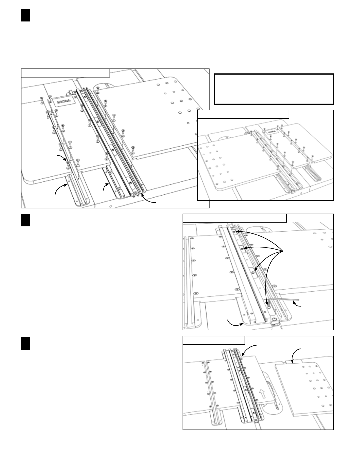
Attach Panels to Utility Plate and Panel Connector
2
Place the Utility Plate in the miter slot selected for use. Orient the Utility Plate so that the small T-slot on the
plate is between the miter slot and your blade. The arrows on the Utility Plate Caution label MUST point toward
the blade. Open Hardware Pack C-13 and using the supplied #10-24 x 15/32” Phillips at head screws, attach the panels
to the Utility Plate and Panel Connector as shown in Figs. 4A and 4B. The large panel will mount to the Utility Plate
using the holes closest to the blade. The small panel with square corners mounts to the opposite edge of the Utility Plate.
Use the Panel Connector to join the small panel with rounded corners to the remaining edge of the small panel with
square corners.
FIG. 4A Panel assembly left of blade
NOTE: All illustrations following Fig. 4B
will show only assembly illustrations for
left side of blade on right tilt table saws.
Large pan el
Small pane l
with roun ded
corner s
#10-24 x 15/32”
Phillips fl at head
screws
Panel connec tor
Adjust Utility Plate for Smooth Glide in
3
Your Miter Slot
Using the included
Small pane l
with squa re
corner s
Utility
plate
3
/
3 2 ” hex key, adjust the (4) expansion
Small T-slot
mechanisms in the Utility Plate for a good sliding t in your
table saw’s miter slot, Fig. 5. Turning the screw clockwise
expands the mechanism. Expand a little at each of the
locations until the Utility Plate slides smoothly with no side
play.
FIG. 4B Panel assembly right of blade
FIG. 5 Adjust utility plate for smooth glide
Adjust all (4)
expansi on mechanisms
NOTE: To relax the expansion mechanism, turn the
screw counter-clockwise as you push down on the
hex key.
3
/32” Hex key
Utility pl ate
Raise Saw Blade and Cut Drop Panel
4
FIG. 6 Cut off drop panel
Utility pl ate
assembly
Drop panel
BLADE ANGLE NOTE: If your primary use for the
Miter Express is mitering with the blade at 90º, make
sure the blade is set at 90º before continuing.
Raise your saw blade about ¾” and make a cut to remove
the portion of the large panel that extends across the line
of cut, Fig. 6. This cut off will be used for the drop panel
described in Step 6. Turn off the saw, lower the blade and
remove the Utility Plate assembly from the saw.
3
Page 4

Adjust Aluminum Miter Bar
5
Using the supplied
3
/
3 2 ” hex key, adjust the aluminum
miter bar at each of the (2) expansion mechanism
locations for a good sliding t in your table saw’s remaining
miter slot. Turning the screw clockwise expands the
mechanism. Expand a little at each of the locations until
the bar slides smoothly with no side play, Fig. 7.
FIG. 7 Adjust aluminum miter bar
Aluminu m miter bar
Expansi on
mechanis ms
3
/32” Hex key
Attach Drop Panel to Aluminum Miter Bar
6
Using (4) #10-24 x ¾” Phillips at head screws,
attach the drop panel to the aluminum miter bar. Use
the mounting holes that permit the least amount of panel
overhang beyond the line of cut, Fig. 8.
Cut Off Drop Panel Overhang
7
Raise the saw blade about ¾” and make a cut to
remove the portion of the drop panel that extends beyond
the line of cut, Fig. 9. Turn off the saw, lower the blade
and return the Utility Plate assembly to the table saw.
CAUTION: In use, only the Utility Plate assembly
slides to move your workpiece through a cut. The
drop panel will be positioned adjacent to the blade
and locked in place by tightening the (2) expansion
mechanisms to provide zero clearance and workpiece
cutoff support. (See Fig. 12)
FIG. 8 Attach drop panel to miter bar
#10-24 x ¾”
Phillips fl at head
screws
Drop panel
Miter bar
FIG. 9 Cut off drop panel overhang
Drop panel
Drop panel o verhang
Attach T-Slot Retainers
8
Note: Skip this step for non T-slot miter channels.
Open Hardware Pack C-14. Slide the Utility Plate panel
assembly to overhang the edge of your table saw and
attach the T-slot retainer using the #10-32 x
3
/
8 ” Phillips
pan head screw as shown in Fig. 10.
The raised rim around the T-slot retainer’s threaded hole
should face upward. Repeat for the opposite end of the
Utility Plate.
4
FIG. 10 Attach T‑slot retainers
Raise d rim face up
#10-32 x ³/₈” Phillips pa n head screw
Utility pl ate
T-Slot retain er
Page 5

Apply UHMW Glide Strips
9
Apply one strip of PSA backed UHMW to the
underside of each of the (3) panels that make up the Utility
Plate panel assembly, Fig. 11.
Align the UHMW so that it contacts only smooth surfaces
on your table saw. The UHMW strips serve to raise the
Miter Express panels just slightly above the drop panel
while simultaneously lowering friction between your table
saw and the panels.
FIG. 11 Apply UHMW glide strips
UHMW strip
NOTE: Do not apply UHMW glide strips to the
underside of the drop panel.
OPeraTIOn
OPeraTIOn
Position and Lock Drop Panel
1
Slide the drop panel assembly in your miter slot and
position adjacent to the saw blade. The infeed edge of
the drop panel should be about 2-3” in front of the saw
blade. Use the
mechanisms to lock the drop panel in place, Fig. 12.
Position Miter Gauge in Receiving Slot of
2
Utility Plate
Slide the Utility Plate assembly into the remaining miter
slot and lower your miter gauge into the receiving slot of
the Utility Plate, Fig. 13.
Once in the receiving slot, a variety of positions for the
miter gauge can be achieved to accommodate different
cutting situations. For small piece work you’ll want the
miter gauge positioned forward on the Utility Plate so that
the work piece will be fully supported by the Miter Express
panels. For maximum crosscut you’ll want to position the
miter gauge fence mounting plate near the infeed end of
the Utility Plate. Figs. 14A and 14B.
3
/
3 2 ” hex key to tighten both expansion
FIG. 14A Gauge position for small piece work
UHMW strip
UHMW strip
FIG. 12 Position and lock drop panel
Tighte n expansion
mechanis ms to
lock drop pa nel in
place
2 - 3”
Drop panel ass embly
FIG. 13 Position miter gauge in receiving slot
FIG. 14B Gauge position for maximum crosscut
3
/32” Hex key
Utility pl ate
Recei ving slot
5
Page 6
Lock the Miter Gauge in Place
3
CAUTION: All THREE of the supplied cam screws
(Hardware Pack C-14) must be positioned and FIRMLY
TIGHTENED against the side of your miter gauge’s
miter bar. CONFIRM that your miter gauge is securely
locked in the Miter Express before making any cuts.
After determining your miter gauge’s position on the Miter
Express (Step 2, Fig. 14A & 14B), remove the gauge from
the receiving slot and install one of the three cam screws
in the threaded cutout that will be closest to the miter
gauge’s protractor head (either in front or behind is OK as
long as it will bear against the miter bar). Install the other
two cam screws so they will be adjacent to any other two
points along the miter bar, Fig. 15A
Use the supplied 1/8” hex key to tighten each cam screw as
far down as it will go, THEN back it out one full turn. Now
rotate each cam screw clockwise until there is enough
head clearance for the miter bar to drop all the way into
the receiving slot. Continue tightening each cam screw
until it is FIRMLY tightened against the miter bar.
NOTE: When properly installed, each cam screw will
be roughly centered on the 3/8” thickness of the miter
bar. This means the cam screws should bear against
the middle of the miter bar, NOT the very top and NOT
the very bottom, Fig. 15B.
FIG. 15A Lock miter gauge in place securely
1
/8” Hex key
Tighte n cam screws
FIG. 15B Cam screw placement- Cutaway View
Cam screw
Miter bar
Make Your Cut
4
Now use your new Miter Express as you would any
miter gauge. Just set your miter angle, check for safe
clearance between your miter gauge’s fence and the blade
and make the cut, Fig. 16.
Be sure to read the accessories section of this manual
for information on the included Outboard Fence
Support and INCRA Hold Down Clamp.
aCCessOrIes
aCCessOrIes
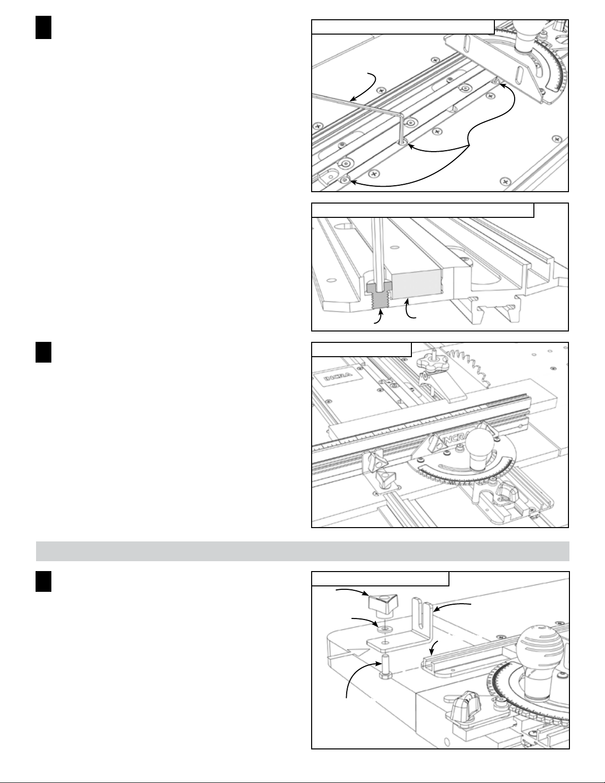
Outboard Fence Support
1
For heavy duty applications, use the included outboard
fence support to provide a rock solid backing for the end
of your miter gauge’s fence. To use the support, open
Hardware Pack C-15. Loosely install one of the ¼-20 x ¾”
hex bolts with washer and ¼-20 knob through the hole in
the outboard fence support, then slide the head of the bolt
into the T-slot on the panel connector, Fig. 17.
FIG. 16 Make your cut
FIG. 17 Outboard fence support
¼-20
Clampin g knob
¼” Washer
Panel connect or
Outboard fen ce
suppor t
6
¼-20 x ¾” Hex bolt
Page 7

For use with most INCRA Miter Gauge fences, you can
use the remaining hex bolts with washers and knobs to
attach the fence to both the outboard fence support and to
the Miter Gauge’s fence mounting bracket, Fig. 18. (You
can continue to use the socket head fasteners provided
with your INCRA Miter Gauge if you prefer.)
In operation, after setting the protractor head angle and
tightening the large clamping knob, you must tighten the
outboard support to the fence before tightening to the
panel connector. After making a cut, be sure to loosen
both clamping knobs before changing miter angles. Try
setting a few angles to get the hang of it.
For use with other non-INCRA miter gauge fences, after
setting the protractor head angle and tightening the large
clamping knob, slide the support up to contact the back
of the fence and tighten the clamping knob to secure the
support to the panel connector, Fig. 19
FIG. 18 Use with INCRA Miter Gauge fences
INCRA
miter ga uge
fence
¼-20 x ¾” Hex bolts
w/washers an d
clampin g knobs
FIG. 19 Use with non-INCRA miter gauge fences
To use the outboard fence support for angle settings that
pivot the fence off of the Miter Express base, you can
shift the position of the panel connector. Just remove
the fasteners and shift the panel connector backward or
forward a few holes, Figs. 20 and 21.
A forward shift is benecial when using the included hold
down clamp for wide material crosscuts, Fig 22.
FIG. 22 Panel shifted to permit clamping wide crosscut
Slide sup port to
contac t rear of fence
and tight en thumbscrew
FIG. 20 Panel connector shifted backward
FIG. 21 Panel connector shifted forward
7
Page 8

INCRA Hold Down Clamp
2
Open the INCRA Hold Down Clamp hardware bag and
assemble the clamp as shown in Fig. 23.
The INCRA Hold Down Clamp slides into either of the (2)
T-slots on the Miter Express to provide a secure grip on
your work piece, large or small. Either end of the clamp
can be used to clamp your workpiece. Just slide the
clamp into the selected T-slot and tighten the clamping
knob, Fig. 24.
FIG. 24 Hold down clamp in use
FIG. 23 Hold down clamp assembly
¼-20 Clamping knob
¼” Washer
Pivot barrel
Clamp body
¼-20 Hex bolt
CAUTION: Never allow any part of the INCRA
Hold Down Clamp to cross the line of cut.
warranTY
Taylor Design Group, Inc. warrants this product for one year from date of purchase. We will repair any defects due
to faulty material or workmanship, or at our option, replace the product free of charge. Please return the failing
component only, postage prepaid, along with a description of the problem to the address below. This warranty
does not apply to parts which have been subjected to improper use, alteration, or abuse.
07/05
Made in America by:
Taylor Design Group, Inc.
Printed in the U.S.A. ✦ © 2005 Taylor Design Group, Inc. ✦ INCRA is a registered trademark of Taylor Design Group, Inc.
INCRA products are protected by one or more of the following U.S. Patents: #4,793,604, #4,930,221, #5,195,730 #5,275,074,
#5,423,360, #5,716,045, #6,237,457, #6,557,601, #6,672,190 Other patents granted or pending.
✦
P.O. Box 810262
✦
Dallas, Texas 75381
✦
Tel: (972) 242-9975
✦
Fax: (972) 243-4277
✦
Web Site: www.INCRA.com
8
 Loading...