

Page 1

Your new INCRA Miter Gauge at
long last solves that frustrating problem
all too familiar to woodworkers –
making perfect miter cuts on the table
saw. Whether you’re constructing a
simple picture frame, complex
compound miters, or a 20-sided object,
your INCRA Miter Gauge delivers
perfect, repeatable accuracy without
trial and error setups – first time, every
time. It’s all made possible by INCRA’s
Angle Indexing System™.
While an
average miter gauge offers positive
stops at 0° and 45° and a good miter
gauge offers stops at 0°, 15°, 221⁄2°,
30°, and 45°, the INCRA Miter Gauge’s
AngleLOCK™ Indexing System
offers
110 stop positions on each side of 0°.
But that’s just half the story. The fence
on your INCRA Miter Gauge is
equipped with INCRA’s patented
Automatic Positioning Control
™
and the
highly versatile INCRA Shop Stop™.
With this combination, you not only
have absolute control over the angle of
your cut, but you also have perfect,
instant control over the length of your
cut as well. Like all INCRA tools, the
INCRA Miter Gauge really does work
EXACTLY as promised.
■
Before using the INCRA Miter Gauge, read
and follow all of the instructions and safety
information in this owner’s manual.
■
When using the INCRA Miter Gauge in
conjunction with any other tool, first read
and follow all instructions and safety
information in that tool's owner's manual.
■
Never let the saw blade come in contact
with the aluminum or steel components of
the INCRA Miter Gauge, including the
fence and the INCRA Shop Stop.
■
When using your INCRA Miter Gauge,
always keep your hands clear of the line of
cut and the saw blade.
■
Always use the tall black knob as a
handle to push your INCRA Miter Gauge
during a cut.
■
Always turn off the power and make sure
that the saw blade comes to a complete
stop before changing the setting of any
part of the INCRA Miter Gauge or INCRA
Shop Stop.
■
Always securely tighten the small black
miter clamping knob before starting any cut.
■
Wear safety glasses, hearing protection,
and follow all normal shop safety
practices.
■
After making any adjustments to the miter
angle or fence position of your INCRA
Miter Gauge, always verify safe clearance
between the blade and fence before
turning on the saw.
■
After making any adjustments to the fence
position on the Incra Miter Gauge, always
make sure the two socket head screws
are securely tightened.
■
Whenever using the INCRA Shop Stop to
position a piece for a cut, always hold or
otherwise clamp the board between the
stop and the blade.
SAFETY
OWNER’S MANUAL
Please read this
owner’s manual
before use and
keep it at hand
for reference.
Important safety instructions for using the INCRA Miter Gauge
®
From the
makers
of the
INCRA JIG!
Page 2

2
Place the INCRA Miter Gauge in
the left hand miter slot at your
table saw. Loosen the (2) 1⁄4-20
socket head cap screws that secure
the fence to the fence mounting
bracket and slide the fence to a
position that leaves safe clearance
between the end of the fence and the
blade. Tighten the (2) 1⁄4-20
fasteners. Fig. 2.
Remove the INCRA Miter Gauge
from the box. Pivot the miter
head around until the hole in the
black bottom plate aligns with the
threaded hole in the miter bar. Insert
the large miter push knob with
washer through the hole and thread
into the miter bar. See Fig. 1.
NOTE:
Do not insert the handle through
the slotted hole.
If the miter slot in your table saw is a
T-slot, attach the “T” clip to the end of
the miter bar as shown in Fig 1A.
1
Hole in bottom plate aligned
over threaded hole in miter bar
Miter push knob
Washer
Bottom plate
Miter bar
FIG. 1
Insert miter push knob through hole in
bottom plate and thread into miter bar.
First: Loosen (2) 1/4-20 socket head cap screws
Clearance between
fence and blade
(at ALL fence angles)
FIG. 2
Position fence
Second: Slide fence
Third: Tighten fasteners
ASSEMBLY
2
FIG. 1A
Assemble miter
bar clip
#10-24 x
5
/16"
flat head screw
T-clip
Miter bar
The method used to join the fence mounting brackets to the miter
head top plate makes it easy to fine-tune the angle of the fence perfectly
perpendicular to your
table top. To adjust, loosen the (3) #10-24 socket head
cap screws that secure the brackets to the top plate and slide a paper or
plastic shim between the bracket and top plate. Placing the shim
behind
the
screws will
decrease
the fence to table angle. Placing the shim in
front
of
the fasteners will
increase
the fence to table angle.
Page 3

CALIBRATION
FIG. 3
Adjust miter bar width
FIG. 4
Second:
Loosen (3) #10 socket
head cap screws that
secure fence mounting
bracket to miter head.
First:
Set miter head to 0°. Tighten
miter lock thumbscrew and lock
actuator tooth in place.
3
Expansion
mechanisms
Machinist
square
Fence
FIG. 5
Fence stops
Second:
Slide
1
⁄4 -20 x 3⁄8" socket head cap
screw and washer up to fence mounting
bracket and tighten in place.
Adjust the Miter Bar
Adjust the miter bar at each of the (6)
expansion mechanism locations for a good
fit in your table saw’s miter slot. Turning the
screw clockwise expands the mechanism. You’ll
find three of the expansion locations in front of
the fence and one underneath the fence (you’ll
need to slide the fence for access). Adjust
these forward (4) expansion points first,
expanding a little at each of the locations until
the bar slides smoothly. Finally, remove the
large miter push knob and pivot the miter head
away from the bar for access to the remaining
(2) expansion points.
Adjust Fence Mounting Bracket 90°
to Saw Blade
Set the miter head to read 0° (the tooth on
the actuator should point to 0° on the
scale). Tighten the miter lock and the actuator
thumbscrews. Using the supplied 5⁄32" hex key,
loosen the (3) #10-24 x 5⁄16" socket head cap
screws that secure the fence mounting bracket
to the miter head. Unplug your table saw, then
use a reliable machinist square to set the fence
at 90° to the saw blade. Tighten the (3) socket
head cap screws.
This one-time calibration prepares your INCRA
Miter Gauge for work in the left hand miter slot.
To calibrate for right hand miter slot usage,
reverse the miter gauge as described on page
5, then repeat the above adjustments. Just
remember that the accuracy of The INCRA Miter
Gauge on any subsequent setting is dependent
upon the accuracy of your initial 90° calibration.
It is a good idea to verify your setup with a trial
cut at 90°.
1
2
T-clip
Miter bar
First:
Find a position for the fence that
provides clearance between fence
and blade at ALL miter head angles.
Safety Tip: Fence Stops
After calibrating your INCRA Miter Gauge
for use in the left miter slot, find a single
position for the fence that provides safe
clearance between the fence and blade at
all angles. Loosely assemble one of the
1
⁄4 -20 x 3⁄8" socket head cap screws with
washer and rectangular nut found in your
hardware pack. Slide the nut into the rear
T-slot on the fence and up to the fence
mounting bracket. Make sure the washer
is firmly against the fence mounting
bracket as you tighten the fastener. See
Fig. 5. Repeat for the right miter slot
setup. Now, when the fence is later
removed for work on the opposite side of
the blade, the fence stop will retain your
original position.
Third:
Use a
machinist
square to
adjust fence
at 90° to
sawblade.
Tighten
fasteners.
Page 4

Half-degree Indexing
To adjust the Miter Gauge to 1⁄2° settings, remove the large
miter push knob from the hole in the top plate and thread it
into the slotted hole. See Fig. 8. Before tightening the knob,
rotate the miter head to move the white “minus” sign engraved
in the black plate toward the knob. Tighten the knob. Now at
every tooth setting for the actuator subtract1⁄ 2°. (Example: If
the actuator tooth is locked at 5°, you are at 41⁄ 2°.)
If you want to add1⁄ 2° to every tooth setting, loosen the
miter push knob and rotate the miter head to move the
white minus sign away from the knob.
Continuous Adjustments
NOTE:
For continuous angle adjustment the miter push
knob should be installed in the hole, not the slot, on the
black bottom plate.
If you need angle settings finer than 1⁄ 2° increments, just
pivot the actuator away from the miter head teeth. You’ll
notice a white hairline cursor engraved in the black plate. Use
this hairline as a reference for your adjustments. For continuous
angle adjustments use only the miter lock thumbscrew to hold
your angle.
Rotate miter head top plate to
desired angle, then firmly engage
tooth on actuator with teeth on miter
head. The actuator tooth should point
directly to the desired angle on the
scale. Tighten the miter lock
thumbscrew, then tighten the actuator
thumbscrew. Fig. 7.
One-degree Indexing
Loosen the actuator thumbscrew
and pivot the actuator tooth away
from teeth on miter head top plate.
Loosen the miter lock thumbscrew.
See Fig. 6.
OPERATION – Changing the Angle Settings
First:
Loosen actuator thumbscrew
and pivot actuator tooth
away from miter head teeth
FIG. 6
Unlock miter
head top plate
Second:
Loosen
miter lock
thumbscrew
Miter head top plate teeth
Actuator
thumbscrew
Actuator
tooth
First: Rotate miter head
to desired angle and
firmly engage actuator
tooth with teeth on miter
head top plate.
FIG. 7
Rotate and engage
actuator, then relock
Second:
Tighten
miter lock
thumbscrew
Third:
Tighten actuator thumbscrew
1
2
4
1
FIG. 8
For 1⁄2° indexing insert miter
push knob through slotted
hole in bottom plate
Miter push knob
Bottom
plate
Slotted hole
2
1
Caution:
After making any adjustments to
the miter angle of your INCRA Miter
Gauge, always verify safe clearance
between the fence and the blade
before turning on the saw.
Page 5
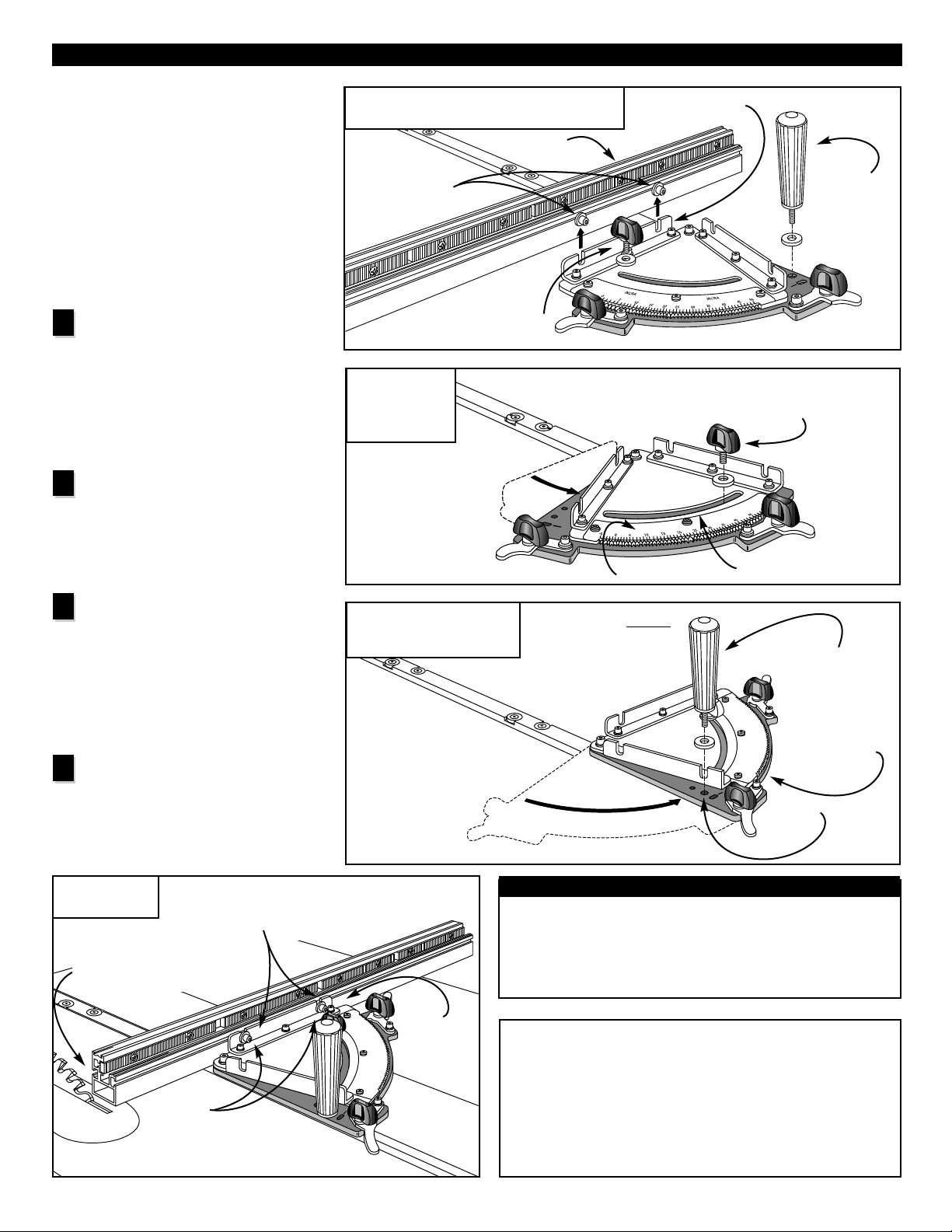
Converting from Left to Right
Miter Slot Use
Your INCRA Miter Gauge is designed for
use in either the left or right miter slot of
your table saw. Since most of the time
you will be using your INCRA Miter
Gauge in the left hand miter slot, the
instructions that follow describe
converting from left to right miter slot
use. To convert back to the original left
miter slot setup, just reverse the steps.
Place the INCRA Miter Gauge in
your table saw's right hand miter
slot. Loosen the (2) 1⁄4-20 socket head
cap screws that secure the fence and lift
the fence straight up and off of the fence
mounting bracket. Remove the large
miter push knob and the small black
miter lock thumbscrew. Fig 9.
Pivot the silver top plate on the
miter head counterclockwise until
you see the threaded hole through the
right end of the slot. Screw the small
black miter lock thumbscrew with washer
into the threaded hole. Fig 10.
Pivot the entire miter head counter-
clockwise until the through hole on
the left side of the black bottom plate
aligns over the threaded hole in the miter
bar. Screw the large miter push knob with
washer into this hole and tighten. Do not
use the slotted hole unless you desire 1⁄2°
indexing. Fig 11.
Lower the fence back onto the fence
mounting bracket. Before tightening
the (2) 1⁄4-20 socket head cap screws,
adjust the fence position to provide safe
clearance between the fence end and the
blade. Tighten the fasteners. Fig 12.
FIG. 9
Remove fence, push knob and miter lock knob
FIG. 10
Pivot top plate
and attach
miter lock knob
REVERSING THE MITER GAUGE
FIG. 11
Pivot miter head and
attach miter push knob
First:
Loosen
1
/4-20
socket head cap
screws and lift
fence off bracket
Fence
Second:
Remove large
miter push
knob
Third: Remove small
miter lock thumbscrew
Fence mounting
bracket
First:
Pivot silver top plate
counterclockwise
Second:
Thread miter lock thumbscrew with washer
into threaded hole at right end of slot.
Top plate
Slot
First:
Pivot entire miter head
until hole on bottom plate
aligns with threaded hole
in miter bar
Second:
Attach push
knob and washer
Bottom plate
Fence
mounting
bracket
Third:
Tighten fasteners
Hole
NOTE:
When using the INCRA Miter Gauge in the
right hand miter slot, use the right hand actuator
and the smaller numbers on the scale to set the
miter head angle.When using the INCRA Miter
Gauge in the left hand miter slot, use the left hand
actuator and the larger numbers on the scale to set
the miter head angle.
Second:
Position fence for safe
clearance between fence
and blade (at ALL angles)
1
2
3
4
First:
Lower fasteners on fence
onto fence mounting bracket
FIG. 12
Reattach fence
5
Do not use the slotted
hole unless you desire
1
/2
° indexing.
Caution:
After making any adjustments to the miter angle
or fence position of your INCRA Miter Gauge,
always verify safe clearance between the blade and
fence before turning on the saw.
Page 6

Zero Clearance
Adding a wooden auxiliary fence to the front
of your INCRA Miter Gauge fence offers
several benefits. Often, the most important
benefit is the ability to add zero clearance
backing for all of your crosscutting and
mitering operations. Azero clearance
auxiliary fence extends beyond the end of the
miter gauge fence and crosses the line of cut
to provide tearout control during a cut. It also
carries any small cutoff pieces safely past the
blade. In the expanded clamping mode, your
INCRA Shop Stop will clamp to your Miter
Gauge fence with auxiliary fences up to 3⁄4"
thick. See Fig. 13.
Extending Stop Range
or Fence Height
Another reason to add an auxiliary fence to
your INCRA Miter Gauge is to extend the
stopping range or fence height when used in
conjunction with the INCRA Shop Stop. By
adding a 3⁄4" plywood or hardwood auxiliary
fence that extends beyond the end of the
miter gauge fence away from the blade and
using the Shop Stop in the standard clamping
mode, you can clamp the stop directly to the
auxiliary fence. Using the Shop Stop in this
way allows the use of taller auxiliary fences
as well.
Attaching an Auxiliary Fence
For auxiliary fence applications where
incremental use of the Shop Stop is required,
the wooden auxiliary fence should be flush
with the top of the INCRA Miter Gauge fence.
Use the dimensions shown in Fig. 14.
Provided in your hardware pack are
1
⁄4-20 x 3⁄4" fasteners with washers
and nuts.
AUXILIARY FENCES
FIG. 13
Zero clearance auxiliary fence
FIG. 14
Auxiliary fence
dimensions
3
⁄4" thick zero
clearance wooden
auxiliary fence
INCRA Shop Stop shown
in expanded mode
2
1
⁄16"
1
1
⁄32"
3
⁄4"
1
⁄4" flat washer
1
⁄4"-20 x 3⁄4
socket head
cap screw
1
⁄4 -20 hex
nut or
rectangular
nut
5
⁄16" thru hole with
3
⁄4" dia. x 3⁄8" deep counterbore
6
NOTE:
Set the INCRA Shop Stop to expanded mode
as described in the Shop Stop owner’s
manual (page 3, Fig. 7) when using an
auxiliary fence up to 3⁄4" thick.
To increase holding power when
crosscutting or mitering, add a strip
of adhesive backed sandpaper to
the front face of your wooden
auxiliary fence. Asandpaper with a
150 to 180 grit works best.
Page 7

ABOUT YOUR FENCE SCALES
7
Fig. 15
Align scales using
optical window
All Incra products use overlapping 16" long Lexan scales. The
overlap allows fine-tuning the scale from one end to the other
to agree with the high degree of accuracy provided by the
Incra saw toothed positioning racks. These scales are printed
initially in 16" lengths (0-16", 16-32", 32-48" etc.). As they are
slid into the scale slot on the fence, the ends are overlapped
and aligned using the optical window located at the end of the
second scale. Fig 15. The friction fit will keep the scales in
place. If you wish, you can use a small piece of double faced
tape at the overlap to ensure that the scales move together
when changing your zeroed setups for mitering.
Page 8

8
Made in America by:
Taylor Design Group, Inc. ■P.O. Box 810262 ■Dallas, Texas 75381 09/2000
Printed in the U.S.A. © 1999, 2000 Taylor Design Group, Inc. INCRA is a registered trademark of Taylor Design Group, Inc.
PRODUCT INFORMATION
For a product information update on the complete
INCRA line of tools, please see your nearest dealer. If
you are unable to locate a store nearby, or if you have
trouble finding a particular product, we will honor your
order directly.
For a product information brochure, call, write or fax to:
Taylor Design Group, Inc.
P.O. Box 810262, Dallas, TX 75381
Tel: (972) 418-4811 Fax: (972) 243-4277
Web Site: www.incra.com
WARRANTY
Taylor Design Group, Inc. warrants this product for one year from date of purchase. We will
repair any defects due to faulty material or workmanship, or at our option, replace the product
free of charge. Please return the failing component only, postage prepaid, along with a
description of the problem to the address below. This warranty does not apply to parts which
have been subjected to improper use, alteration, or abuse.
LIFETIME WARRANTY ON POSITIONING RACKS
If an INCRA linear positioning rack in this tool becomes damaged for ANY reason,
Taylor Design Group will replace it free of charge for as long as you own your tool.
Return the damaged rack, transportation prepaid, and allow 1 to 2 weeks for delivery.
PARTS AND OPTIONAL ACCESSORIES
PART # PART DESCRIPTION PRICE
SHOPSTOP INCRA Shop Stop . . . . . . . . . . . . . . . . . . . . . . . . . . . . . . . . . . . . . . . . . . . . . . . . . . . . . . $ 32.95
Add a second Shop Stop to your IncraLOCK™Cut-off Fence
MITERFNC27 27" IncraLOCK™Cut-off Fence . . . . . . . . . . . . . . . . . . . . . . . . . . . . . . . . . . . . . . . . . . . $ 34.95
Extra 27" IncraLOCK™Cut-off fence with positioning racks
MITERFNC52 52" IncraLOCK™Cut-off Fence . . . . . . . . . . . . . . . . . . . . . . . . . . . . . . . . . . . . . . . . . . . $ 49.95
Extended 52" IncraLOCK™Cut-off fence with positioning racks
 Loading...