

Page 1
w w w. i n c r a . c o m
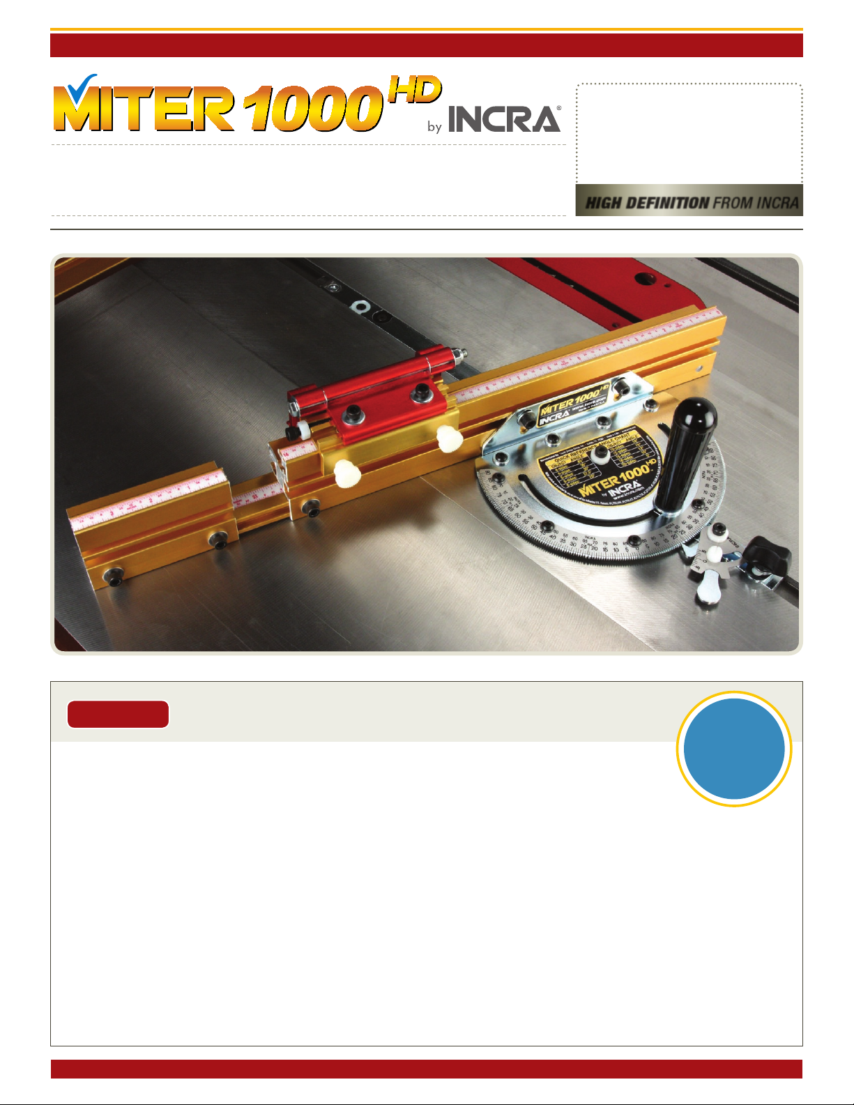
BEFORE USING THE INCR A
MIteR1000HD, READ AND FOLLOW
ALL OF THE INSTRUCTIONS AND
SAFETY INFORMATION IN THIS
OWNER’S MANUAL.
O’ M
high definition
high definition
from incra
SAFETY:
Important safety InstructIons for usIng the INCRA MIteR1000HD
REGISTER
YO U R
When using the INCR A Miter1000HD in conjunction with any other tool, first read and follow all
°
instructions and safety information in that tool’s owner’s manual.
Never let the saw blade come in contact with the aluminum or steel components of the INCRA Miter1000HD.
°
When using the INCR A Miter1000HD, always keep your hands clear of the saw blade and the line of cut.
°
Always turn off the power and make sure that the saw blade comes to a complete stop before changing the setting of any part of
°
the INCRA Miter1000HD.
Always securely tighten the large black clamping knob before starting any cut.
°
Wear safety glasses, hearing protection, and follow all normal shop safety practices.
°
After making any adjustments to the miter angle or fence position of your INCRA Miter1000HD, always verify safe clearance
°
between the blade and fence before turning on the saw.
After making any adjustments to the fence position on the INCR A Miter1000HD, always make sure that the two socket head
°
screws are securely tightened.
When using the INCR A Flip Shop Stop to position a piece for a cut, always hold or otherwise clamp the board between the stop
°
and the blade.
Manufac tured by Taylor D esig n Group, In c. P.O. BOX 810262 Da lla s, TX 75381 ©2 008 by Tayl or De sign Grou p, Inc. All r ight s reserve d.
PRODUCT
ONLINE
WWW.INCR A.CO M
Page 2
INCRA M Ite R100 0H D OWNER’S M ANUAL
Assembly and Calibration
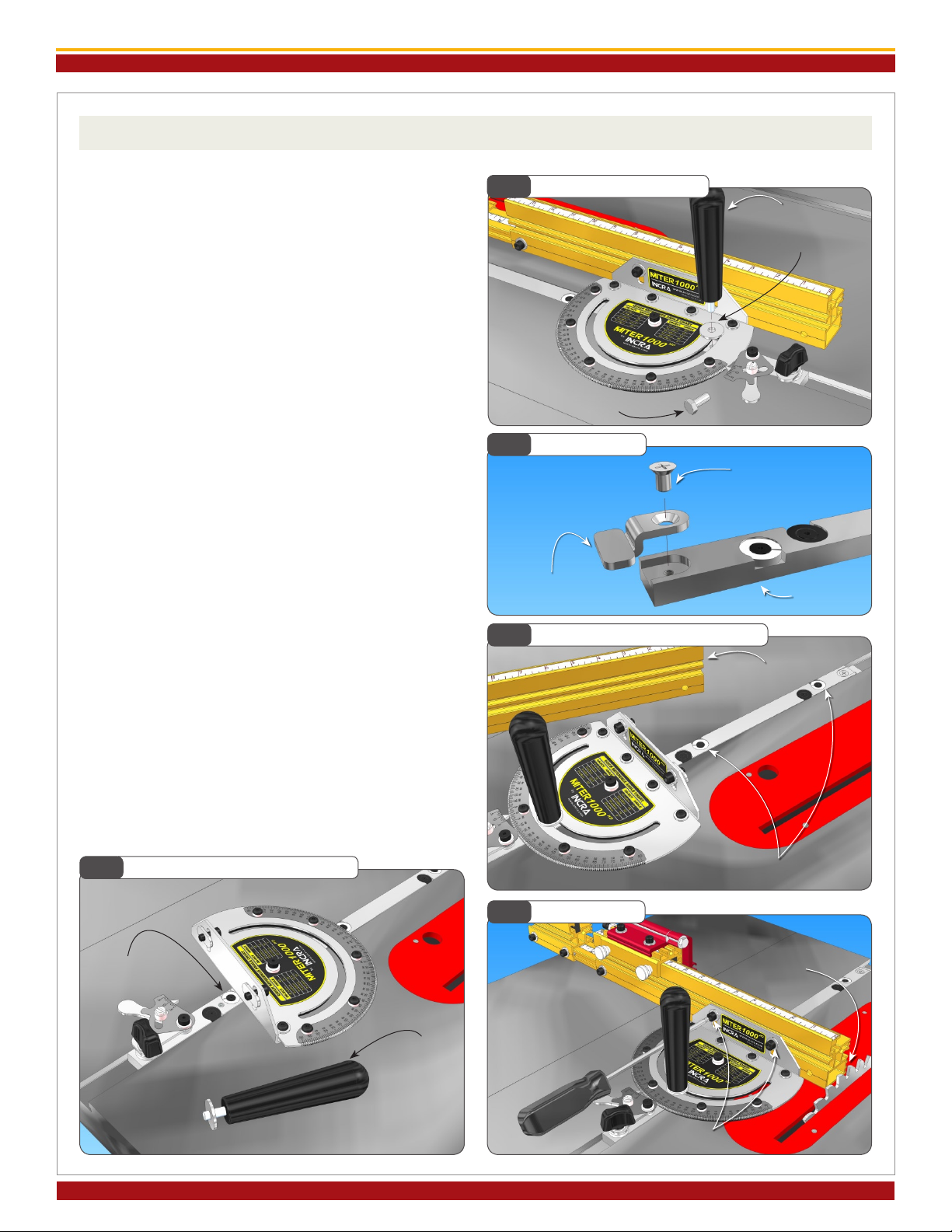
1. Attach Clamping Knob and T-Clip
Remove the hex bolt that secures the protractor head
and replace with the large threaded knob included in
the hardware pack. The washer on the hex bolt must
be used with the threaded knob, Fig. 1. If the Miter
slot in your table saw has a T-slot, attach the T-clip to
the end of the miter bar as shown in Fig. 2.
2. Adjust the Miter Bar
Loosen the (2) fasteners that secure the fence to the
fence-mounting bracket and remove the fence. Adjust
the miter bar at each of the (3) expansion mechanism
locations in the miter bar for a good t in your table
saw’s miter slot. Turning the screw clockwise expands
the mechanism. You’ll nd (2) of the expansion locations in front of the protractor. Adjust these (2) front
expansion points rst, expanding a little at each of the
locations until the bar slides smoothly, Fig. 3.
Remove the large clamping knob with washer and
pivot the protractor head to gain access to the rear
expansion point, Fig. 4. After adjustment, replace the
washer and large clamping knob.
Attach Clamping Knob
Fig. 1
Remove hex bolt
Attach T-Clip
Fig. 2
T-clip (use only in T-slot
miter channels)
Expand Miter Bar to Fit (front)
Fig. 3
Large knob
Washer
#10-24x1/4”
Phillips at head
screw
Miter bar
3. Attach the Fence
Place your Miter1000HD in the preferred miter slot
at your table saw. (Note: Left hand miter slot use
shown. See step 4 to convert fence for use in right
hand miter slot.) Attach the fence to the fence mounting
bracket and slide the fence to a position that leaves
safe clearance between the end of the fence and the
blade. Tighten the (2) 1/4-20 fasteners, Fig. 5.
Expand Miter Bar to Fit (rear)
Fig. 4
Adjust rear
expansion point
Remove knob
and rotate
protractor for
access.
Replace af ter
adjusting
rear expansion point.
Fig. 5
Attach Fence
Fence removed for
access
Adjust (2) front expansion points
Position for safe
clearance between fence
and blade
1/4-20 socket head screws
Page 2
Manufac tured by Taylor D esig n Group, In c. P.O. BOX 810262 Da lla s, TX 75381 W W W. I N CR A . C OM
Page 3
INCRA M Ite R100 0H D OWNER’S M ANUAL
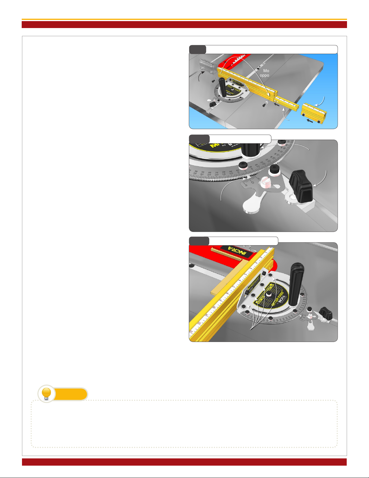
4. Left or Right of Blade
Your new Miter1000HD fence is factory congured
for use to the left of the blade. If you prefer to use
your Miter1000HD in the right hand miter slot just
follow the steps below.
Loosen the 1/4-20 socket head screw located at the
end of the 14” section of the fence, then slide out the
4” section of fence along with the attached extender
bar. Move the socket head screw, washer and rectangular nut to the hole on the opposite end of the fence.
Slide the extender bar assembly into the end of fence,
capturing the rectangular nut in the T-slot on the
extender bar. The higher numbers on the extender
bar scale should be closest to the saw blade. Loosen
the (2) socket head fasteners that secure the 4”
section of fence and reverse it. Tighten all fasteners,
Fig 6. Slide the scale in the top of the fence out
and replace with the included reverse reading (0-14”)
scale.
Converting Fence for use on Right Side of Blade
Fig. 6
Remove
extender bar
assembly
Fig. 7
Actuator tooth
engaged at 0°
opposite end of fence
Set Protractor to 0°
Move fasteners to
Extender bar
4” fence section
Tighten large
clamping knob, then
tighten actuator
thumbscrew
5. Ad j ust Fence Mount ing Bracket 90°
to Saw Blade
Fig. 8
Square Fence to Blade
Set the protractor head to read 0°, engaging the tooth
on the actuator rmly into the 0° notch on the protractor
head, Fig. 7. Tighten the large clamping knob then tighten
the actuator thumbscrew.
Using the supplied 1/8” hex key, loosen the (4) socket
head screws that secure the fence-mounting bracket
to the protractor head. Unplug your table saw, then
use a reliable machinist square to set the fence at 90° to
the saw blade, Fig. 8. Tighten the (4) socket head screws.
Loosen socket head screws and adjust
fence using reliable machinist square
This one time c alibr a t ion pre pares your INCR A
Miter1000HD for work in either miter slot. Just remember that the accuracy of the INCRA Miter1000HD at
any subsequent setting is dependent upon the accuracy of your initial 90° calibration. Verify this important
calibration with a test cut and ne tune as necessary.
TIP
Squaring the fence to your table saw top
e method used to join the fence-mounting bracket to the protractor head makes it easy to fine-tune the fence
perfectly perpendicular to your tabletop. To adjust, loosen the (4) socket head screws that secure the bracket and
slide a paper shim between the bracket and the underside of the protractor head. Placing the shim behind the screws
will increase the angle. Placing the shim in front of the screws will decrease the angle.
Page 3
©200 8 by Tay lor D esig n Grou p, In c. All righ ts re ser ved. R ev.12.23.08
Page 4

INCRA M Ite R100 0H D OWNER’S M ANUAL
Operation – Changing Angle Settings
Before using yo u r new INC R A M iter1000HD for
the rst time, take a few moments to review these
important operational procedures.
1. 1° Indexing (including 22-1/2° settings)
Loosen the actuator thumbscrew and pivot the
ac tuator tooth away from the notches located on the
perimeter of the protractor head. Loosen the large
clamping knob and rotate the protractor head and
fence to the desired angle, Fig. 9. Then rmly engage
the tooth on the actuator with the corresponding
notch on the protractor head. The actuator tooth
should point directly to the desired angle on the scale.
Tighten the large clamping knob, then tighten the
actuator thumbscrew, Fig. 10.
2 . C o nt i n uo u s A dj u st m e n ts (f o r a ng l e
settings ner than 1° increments)
Pivot the actuator tooth away from the notches on
the protractor head, aligning the arm over the miter
bar, and tighten the thumbscrew. Now loosen the
small nylon thumbscrew on the actuator and pivot the
1
/
10° vernier cursor toward the scale. Rotate the cur-
sor until it is aligned edge to edge with the scale and
tighten the thumbscrew. When you change miter
angles, just align the desired angle on the scale with
the “0” cursor line, Fig. 11. For 1/10° adjustments,
use the alignments as described in the 1/10° vernier
instructions on page 8.
Miter1000HD
Changing Angles
Fig. 9
Rotate protractor
Fig. 10
Locking the Protractor
Pivot the actuator tooth
away from protractor
Loosen large
clamping knob
and actuator
thumbscrew
Tighten large clamping
knob then tighten
actuator thumbscrew
Fig. 11
Continuous Adjustments
Firmly engage
actuator tooth with
protractor
CAUTION:
AFTER MAKING ANY ADJUSTMENTS TO T H E
Pivot cursor
to scale
MITER ANGLE OF YOUR INCRA MITER1000HD,
ALWAYS VERIFY SAFE CLEARANCE BETWEEN
THE FENCE AND THE BLADE BEFORE TURNING
Pivot actuator tooth away from
protractor and tighten thumbscrew
Page 4
Manufac tured by Taylor D esig n Group, In c. P.O. BOX 810262 Da lla s, TX 75381 W W W. I N CR A . C OM
ON THE SAW.
Page 5

INCRA M Ite R100 0H D OWNER’S M ANUAL
Flip Fence and Flip Shop Stop - Calibration and Operation
As you look at your new INCRA Flip Shop Stop and
Flip Fence for the rst time you will see an interesting
detail. The front face of the fence uses a tongue and
groove arrangement to accept a mating feature on the
ip arms, Fig. 12. When the ip arm is down with
the two opposing features engaged, it becomes
im possible for the sharp corner of a mitered board
end to wedge between the fence and ip arm. Combined with INCRA’s famous incremental positioning
capabilities, you’ll soon be duplicating cut off lengths
with machine shop precision.
Zeroing the Fence Scales
To zero the main fence scale for 90° work, rst set
the protractor to the 0° setting and lock in place.
Clamp the Flip Shop Stop to the fence so that the 0”
mark on the fence scale reads directly under the end
of the gold component of the Flip Shop Stop, Fig. 13.
Now loosen the (2) 1/4-20 socket head screws that
secure the fence to the fence mounting bracket and
slide the fence toward the blade until the Flip Arm on
the stop contacts the blade. Re-tighten the fasteners,
Fig. 13A.
Fig. 12
Fig. 13
Flip Shop Stop
Zeroing Fence Scale
Clamp Flip Shop Stop at
0” position
Tongue and groove
Protractor
set at 0°
For stopped cuts beyond the range of the main fence you’ll need to
calibrate the extender bar scale. Clamp the INCRA Flip Shop Stop to
the 4” fence extender. (Use the scale on the short section of fence as
a reference for clamping the stop to the same position each time you
use it.) Now loosen the 1/4-20 socket head screw located at the end
of the longer fence and slide the 4” fence and extender bar out. Use
a tape measure to set the distance between the blade and the ip arm
at 16” and re-tighten the fastener, Fig. 14. Now simply slide the scale
in the extender bar to read 16” at the end of the longer main fence
section, Fig. 14A.
Fig. 14
Setting Extender Bar Scale
Slide extender bar out
until ip arm is 16” from
blade then tighten fastener
Loosen fastener
Clamp
stop to
4” fence
section
Fig. 14A
16” at end of main fence
Fig. 13A
Align Scale
Slide scale to read
Slide Fence to Blade
Slide fenc e until ip
arm contacts blade,
then tighten fasteners
Page 5
©200 8 by Tay lor D esig n Grou p, In c. All righ ts re ser ved. R ev.12.23.08
Page 6

INCRA M Ite R100 0H D OWNER’S M ANUAL
For mitered cutting, a test cut is often the most accurate means of setting the fence and extender bar
scales since measuring to the tooth of a blade set at
an angle to the fence can be difcult. Begin by setting
the desired miter angle and check for safe clearance
between the fence and blade. Clamp the stop to the
fence about 10” away from the blade. Miter a piece of
scrap stock with this setup. Measure the length of the
cut piece, Fig. 14B. Then simply slide the scale on
the fence to read the length of the cut directly under
one end of the stop.
Micro Adjusting
To micro adjust your Flip Shop Stop’s position, begin
by loosening the (2) socket head screws located on
the top of the stop body. Now turn the micro adjust
socket head screw to fine tune the stop position,
Fig. 15. When unscrewing the micro adjust screw,
apply pressure to the stop body to keep it against the
screw end. After adjustment, always tighten the (2)
socket head screws on top of the stop body.
Fig. 14B
Fig. 15
Micro Adjusting
Loosen (2) socket
head screws
Setting Scales for Angled Cuts
Measure length
of cut
Slide scale to
read cut length
here
Flip Arms and Stop Rods
The dual ip arms and stop rods provide a variety of
stop congurations. The ip arms can be used without
the stop rods when you want to take advantage of the
fence/arm tongue and groove feature for stop control
on mitered board ends. Typically, you will use the
longer rod to join the two arms together, Fig. 16. This
produces an arrangement that, when pivoted, moves
both arms simultaneously. The rod can be positioned
so that it is the actual stop surface or it can be positioned slightly behind the front of the arm so that the
aluminum arm is the actual stop surface.
By placing one of the shorter 1-1/2” rods in each of
the two stop arms, you can use the two stop arms
independently, Fig. 17. For example, you can calibrate
one for work to the left of the blade and the other
for work to the right. On one side of the blade you
might want to position the stop rods to provide two
different cut off lengths from one stop position. By
using varying combinations of long or short rods you
can create as much as 7-3/4” between the two stop
positions.
Fig. 16
Fig. 17
Long Stop Rod
Short Stop Rods
Turn this socket head screw
to adjust
Long stop rod used to
join ip arms
Short stop
rods allow
independent
ip arm
use
Page 6
Manufac tured by Taylor D esig n Group, In c. P.O. BOX 810262 Da lla s, TX 75381 W W W. I N CR A . C OM
Page 7

INCRA M Ite R100 0H D OWNER’S M ANUAL
Making a Zero Cleara nce Wooden Su b
Fence
A sub fence can be used to provide tear out control as
well as support for your workpiece up to and beyond the
Fig. 18
Making a Sub Fence
2-1/2” max (see note)
5/16” through hole w/
3/4” dia. x 3/8” deep
counter bore
blade. A good material to use for making your zero
clearance sub fence is 3/4” medium density fiberboard
rectangular nut
(MDF). Use the drill and counter bore dimensions
shown in Fig. 18. Attach using the supplied fasteners. Adjust the length of the fence to accommodate
your application. Note: In applications where the
incremental stopping capability of the Flip Shop Stop
1/4-20 x 3/4”
socket head screw
1/4” at washer
1-1/16”
3/4”
is required, the wooden sub fence can be no taller
than 2-1/2”.
TIP
To avoid the saw blade pulling your workpiece into the cut, add a strip of adhesive backed sandpaper to the front
face of the wooden sub fence.
1/4-20
Expanded Flip Stop Clamping Mode
The two-part body design of the INCRA Flip Shop
Fig. 19
Expanded Flip Stop Clamping Mode
Gold component
Stop allows for use with up to a 3/4” thick wooden sub
fence. To expand the INCRA Flip Shop Stop, loosen
the (2) socket head screws located on the top of the
stop body, then slide the upper portion of the stop
off. Now slide the upper portion back on, capturing
the rectangular nuts in the second T-slot located on
the lower portion (gold component) of the stop body,
Sub fence
Loosen socket head
screws and slide red
assembly into 2nd T-slot
on gold c omponent
Fig.19.
WARRANTY
TAYLOR DESIGN GROUP, INC. WARRANTS THIS PRODUCT FOR ONE YEAR FROM DATE OF PURCHASE. WE
WILL REPAIR ANY DEFECTS DUE TO FAULTY MATERIAL OR WORKMANSHIP, OR AT OUR OPTION, REPLACE
THE PRODUCT FREE OF CHARGE. PLEASE RETURN THE FAILING COMPONENT ONLY, POSTAGE PREPAID,
ALONG WITH A DESCRIPTION OF THE PROBLEM TO THE ADDRESS BELOW. THIS WARRANTY DOES NOT
APPLY TO PARTS WHICH HAVE BEEN SUBJECTED TO IMPROPER USE, ALTERATION, OR ABUSE.
LIFETIME WARRANTY ON POSITIONING RACKS
IF AN INCRA POSITIONING RACK IN THIS TOOL BECOMES DAMAGED FOR ANY REASON, TAYLOR DESIGN
GROUP WILL REPLACE IT FREE OF CHARGE FOR AS LONG AS YOU OWN YOUR TOOL. RETURN THE DAMAGED RACK, POSTAGE PREPAID, PLEASE ALLOW 1 TO 2 WEEKS FOR DELIVERY.
Page 7
©200 8 by Tay lor D esig n Grou p, In c. All righ ts re ser ved. R ev.12.23.08
Page 8

INCRA M Ite R100 0H D OWNER’S M ANUAL
0° 1/10° left of 0° 2/10° left of 0° 3/10° left of 0°
9/10° left of 0°8/10° left of 0°
Your new M it er1000 HD fea tu res severa l enhanceme nt s not incl uded w it h the
standard M it er100 0. Am on g these i s the new 1/10° ver ni er cursor.
For readi ngs in 1° increments using the cursor, just align any of the protractor scale
marks with the “0” ma rk on the cursor. For 1/10° adjust ments, you wil l notice 5 marks
on either side of the “ 0” mark on the cursor. As you gentl y rotate the protractor you
will read the scale as fol lows: At 1/10° rotat ion, the rst mark aligns 1° away from the
original start ing point. At 2 /10 ° rota tion, the second mark aligns 2 ° away. At 3/10 °
rotat ion, the third mark aligns 3° away, etc. For 6/10 ° through 9/10 ° of rotat ion, watch
for al ignment s using the m arks on the opposite side of t he “0” cursor mark.
Sound complicated? It’s not! Just study th e examples on t his page.
5/10° lef t of 0° 6/10° left of 0° 7/10° left of 0°4/10° left of 0 °
Using Your New
1/10
° Vernier Cursor
Manufactured by:
Taylor Design Group, Inc.
P.O. BOX 8102 62 Dallas, TX 753 81
www.incra.com
INCRA is a Registered Trademark of Taylor Design Group, Inc.
©200 8 Taylor Design Group, Inc.
INCR A Tools are pro tect ed by one o r more of the f oll owin g US pat ents :
#4, 793, 60 4, #4,93 0,2 21, #5,195,73 0, # 5,2 75,074 , #5, 42 3,3 60, # 5,716,04 5, # 6,2 37,457,
#6,5 57,601, #6,67 2,190. Other patents grante d or pendin g.
Page 8
Manufac tured by Taylor D esig n Group, In c. P.O. BOX 810262 Da lla s, TX 75381 W W W. I N CR A . C OM
MADE IN THE
USA
©200 8 by Tay lor D esig n Grou p, In c. All righ ts re ser ved. R ev.12.23.08
 Loading...