

Page 1
Owner’s Manual
25971
Please read before use and keep it at hand for reference.
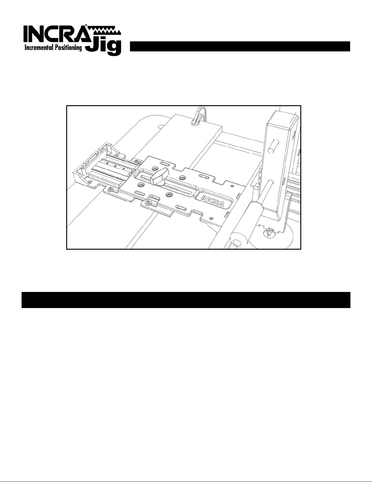
Since its first appearance in woodworking shops around the globe many years
ago, INCRA Jig has established itself as the finest and most versatile woodworking system available. At the top of its list
of features has always been its unparalleled positioning accuracy. As a fence system, INCRA Jig’s amazing precision
allows exact fence placement to within a few thousandths of an inch, regardless of your skill level. As a joint making
machine, these same positioning capabilities permit an endless variety of box joints and all styles of dovetails to be
created. And with decorative joints like the exquisite INCRA Double Dovetail (described in the INCRA Master Reference
Guide and Template Library sold separately), INCRA Jig makes the seemingly impossible quite possible.
This owner’s manual is an ideal companion to the superb instructional DVD included with the purchase of your new
INCRA Jig. Please take an hour or so to view this enjoyable video production. You will see and hear in real life,
everything that is illustrated and written in this manual, and you will soon be on your way to unleashing the awesome
capabilities that the world famous INCRA Jig will put in your shop. As a bonus, you’ll also learn a host of useful
information about general purpose router table techniques that you can apply to all your woodworking projects.
SAFETY
x Before using the INCRA Jig, carefully read and follow
all of the instructions and safety information in this
manual.
x When using the INCRA Jig in conjunction with any
other tool, first read and follow all instructions and
safety information in that tool’s owner’s manual.
x When the INCRA Jig is mounted to a wooden base or
table surface, make sure that all four mounting screws
are securely tightened and the INCRA Jig is firmly held
in place.
x When using the INCRA Jig with a wooden base panel,
always make sure that the base is securely clamped,
screwed or otherwise fastened to the work surface
before making a cut.
x Always turn off the power and make sure that the bit or
blade is fully stationary before moving the INCRA Jig to
any new setting.
Important safety instructions for using the INCRA Jig
x Always keep both hands behind the fence when
moving the INCRA Jig to any new setting.
x Before making a cut, always make sure that the
clamping knob is fully tightened and the jig is securely
locked in place.
x When using the INCRA Jig with other tools, make sure
that all safety guards and other safety equipment
supplied by the manufacturer of that tool are securely
in place and functional. Never let the INCRA Jig
interfere with another tool’s safety equipment.
x Use appropriate safety devices. Keep hands clear of
the bit or blade. Always use a push stick, rubber soled
push block, or other safety devices to keep your hands
safely away from the cutting tool.
x Wear safety glasses, hearing protection and a dust
mask, and follow all normal shop safety practices.
RTD10000168AA
1
Page 2
INCRA Jig Assembly
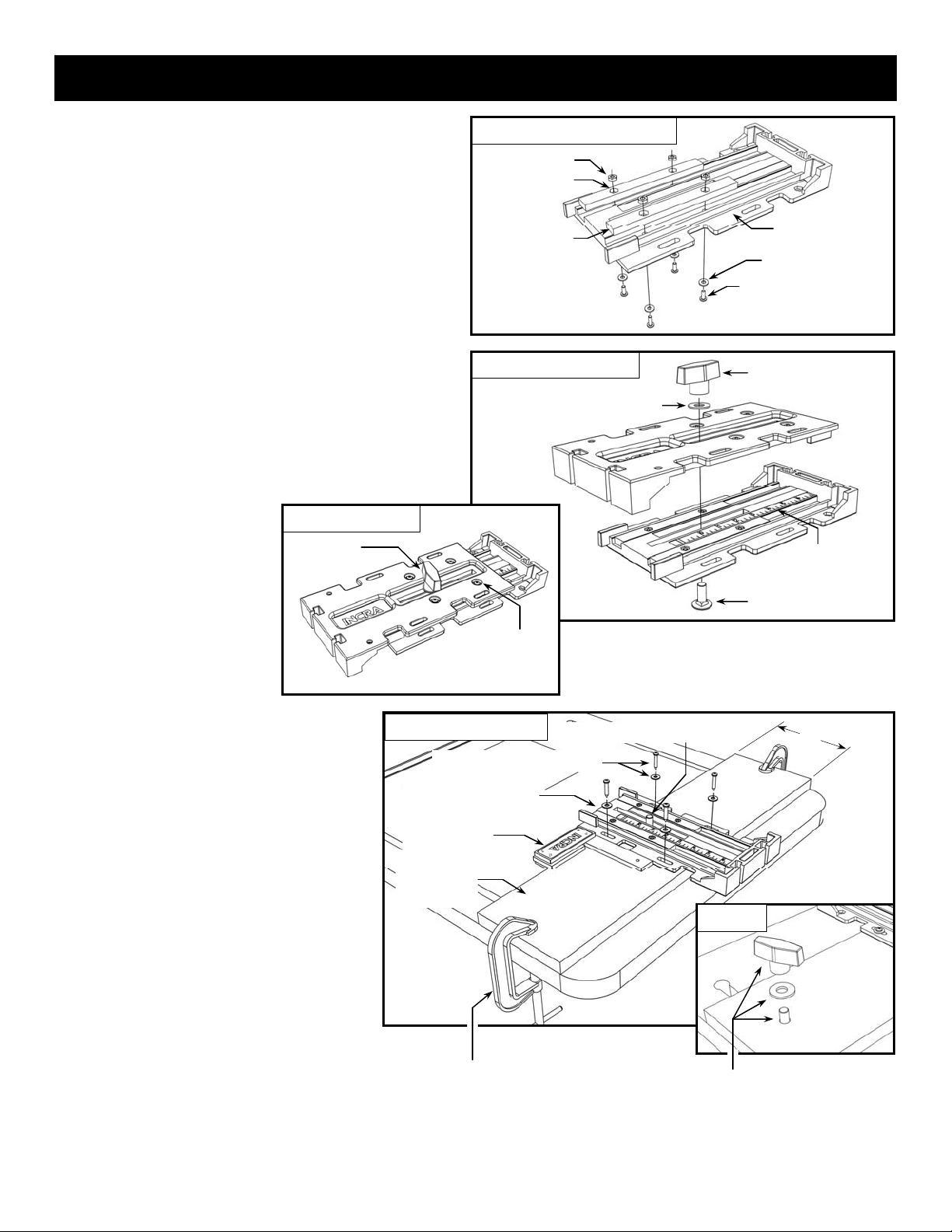
Step 1. Attach sawtooth positioning racks.
Begin by assembling the (4) INCRA sawtooth racks to
the (2) INCRA Jig body halves. Place a rack into one of
the receiving grooves and align the mounting holes.
Now place the 8-32 hex nuts from hardware pack D-01
into the hex recesses on the rack and loosely fasten
using the 8-32 Phillips screws with washers, Fig. 1.
Repeat for all of the remaining racks. For now, finger
tighten only. The racks should still be loose enough to
shift slightly back and forth.
Step 2. Clamp INCRA Jig body halves
together.
IMPORTANT: Before proceeding, make sure that the
racks installed in Step 1 are still a little loose .
Place the two INCRA Jig body halves together as shown
in Fig. 2 and install the carriage bolt, large washer and
2-wing clamping knob from hardware pack D-01.
IMPORTANT: The body half
with the scale should be on
the bottom. Set the top half to
a position of about 5 inches
(not critical) as indicated on the
bottom scale, then tighten the
clamping knob. Now securely
tighten all (8) Phillips screws,
Fig 2A. This procedure aligns
the racks automatically and
perfectly.
Fig. 2A Tighten racks
First: Tighten
clamping knob
Fig. 1 Install INCRA sawtooth racks
8-32 hex nut (8)
Hex nut in recess
Sawtooth rack (4)
Fig. 2
Second: Tighten all (8)
Phillips screws (4 top,
4 bottom)
Clamp halves together
Large washer
INCRA Jig body half (2)
#8 flat washer (8)
8-32 x 7/16“ Phillips screw (8)
2-wing clamping knob
Body half with scale is
on the bottom
Carriage bolt
Step 3. Attach INCRA Jig to base
panel.
To attach the INCRA Jig to your router table,
you’ll need a piece of 3/4” thick by 9” wide
plywood or MDF that’s long enough to span
the width of your router table. Remove the top
half of your INCRA Jig and center the bottom
half, scale side up on the panel. (Be sure the
carriage bolt is properly installed from
underneath as shown.) Center and square the
INCRA Jig on the panel, then attach it with the
#10 x 1” wood screws with washers included
in hardware pack D-02. Now replace the top
half of the INCRA Jig along with the washer
and clamping knob. Secure the base to your
router table with a pair of C-clamps as shown
in Fig. 3, or if your router table is “INCRAready”, with slotted holes, you can attach the
base panel with user provided T-bolts,
washers and clamping knobs, Fig. 3A. Just
drill holes in the base panel to align with your
router table slots.
Fig. 3
Attach to base panel
#10 x 1” wood screw & washer (4)
Bottom INCRA Jig body half
(with measuring scale)
Square INCRA Jig to
base panel
3/4” plywood or
MDF base panel
Carriage bolt in place before mounting
Use C-clamps to attach a 3/4” thick by
9” wide plywood or MDF base panel to
your router table . . .
2
9”
Fig. 3A
… or, if your router table is “INCRA-ready” with
built-in mounting slots, you can attach the base
panel with T- bolts, washers and knobs for
greater ease of use
Page 3
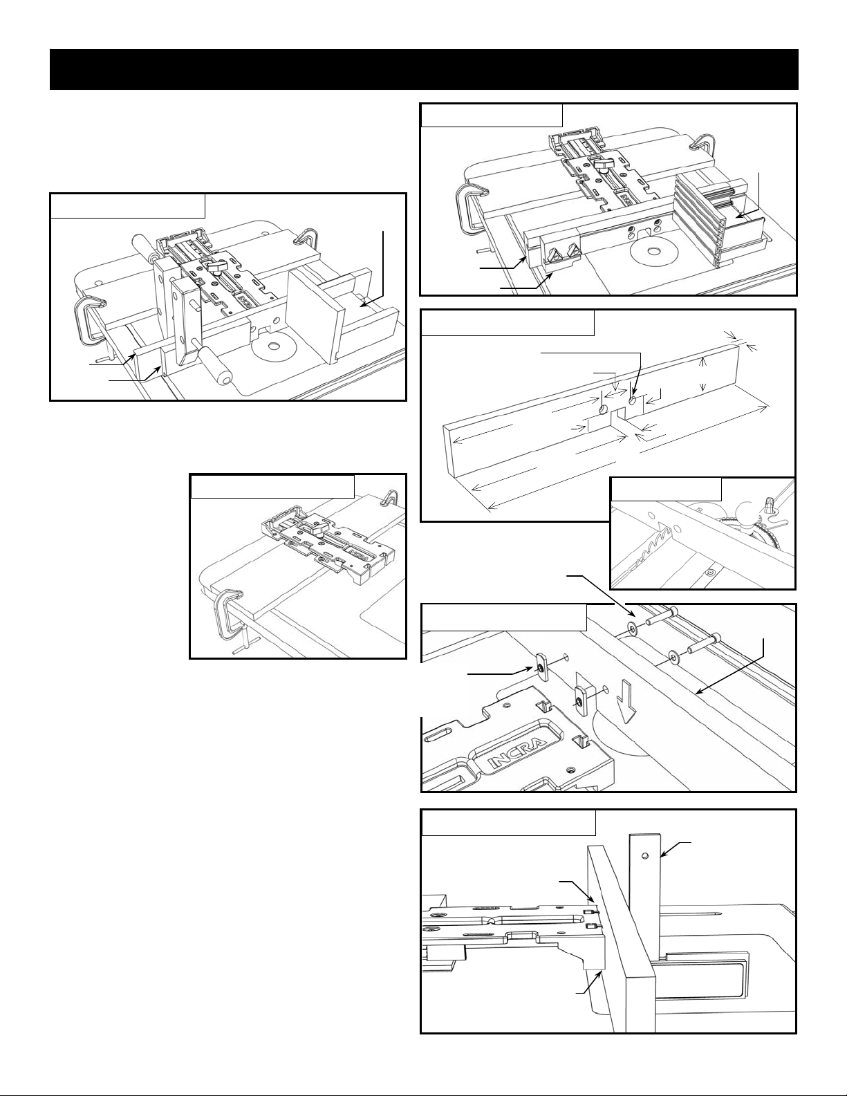
User Made Accessories - Fence
Note: If you have purchased the factory INCRA Fence
System shown in Fig. 4 (recommended), use the
instructions included with that product to assemble and
attach to your INCRA Jig. Follow the instructions below
if you would prefer to make your own, Fig. 5.
Fig. 5
Fence
Stop
User made accessories
Right angle
fixture
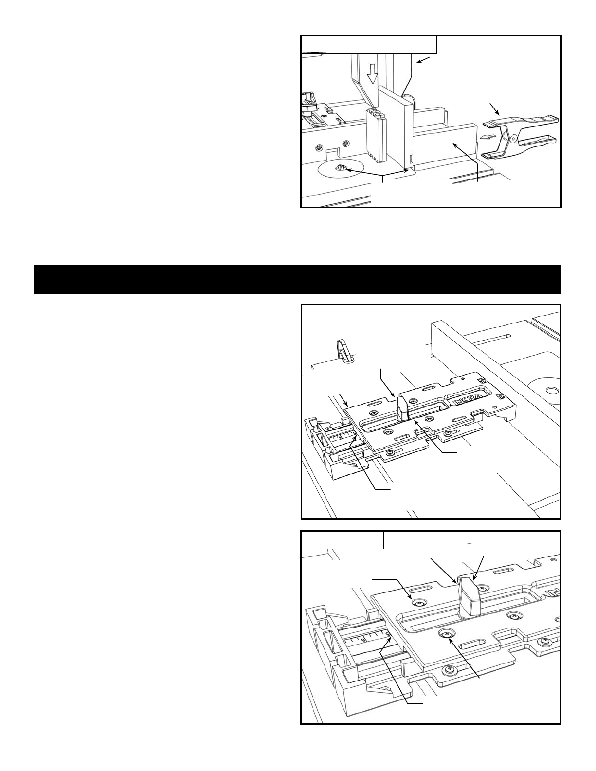
Making and attaching your fence.
Begin by making the fence as dimensioned in Fig 6.
Use a straight piece of 3/4” MDF, hardwood or plywood.
Layout the position
for the notch, then
cut the waste away
with multiple side-byside passes at the
table saw using a
miter gauge to guide
the material, Fig. 6A.
Fig. 7
Clamp INCRA Jig to table
Fig. 4
T-slot fence
Stop positioner
Fig. 6
Factory Accessories
User made fence dimensions
5/16” diameter through hole
with 5/8” diameter by 3/8” deep
counter bore (2)
1/4-20 x 7/8 socket head cap
screw and washer (2)
INCRA
Right angle
fixture
3/4”
2 1/2”
”
4
/
3
0
1
1”
”
8
/
3
1
1
1 5/16”
”
4
2
Fig. 6A
4
/
1
1
Cut notch
3”
”
IMPORTANT:
Before attaching the
fence, the INCRA Jig
must first be securely mounted to a 3/4”
wooden base panel and the base panel must
be clamped to your router table. Also make
sure that the INCRA Jig’s clamping knob is
securely tightened, Fig. 3 & Fig. 7.
Attach the fence to your INCRA Jig front end using the
1/4-20 x 7/8” socket head fasteners with washers and
rectangular nuts from hardware pack D-02.
CAUTION: The raised rim on the two rectangular
nuts MUST FACE AWAY from the fence as shown in
Fig. 8. Now slide the rectangular nuts into the T-slots
located at the front end of the INCRA Jig’s top body half
and tighten the fasteners to secure.
After attaching your fence, check for squareness with
your router table top. If any adjustment is necessary,
loosen the mounting screws and insert a paper or plastic
shim between the INCRA Jig and the rear of the fence,
Fig. 9. A shim placed below the fasteners will increase
the angle between the fence and table; a shim placed
above the fasteners will decrease the angle. Tighten the
fasteners to secure the fence.
1/4-20 rectangular nut (2).
Raised rim MUST face AWAY
from the fence
Fig. 8
Fig. 9
Attach fence to INCRA Jig
Square Fence to router table
Place shim between top of jig and
fence to decrease angle
Place shim between bottom of jig
and fence to increase angle
3
Fence
Square
Page 4
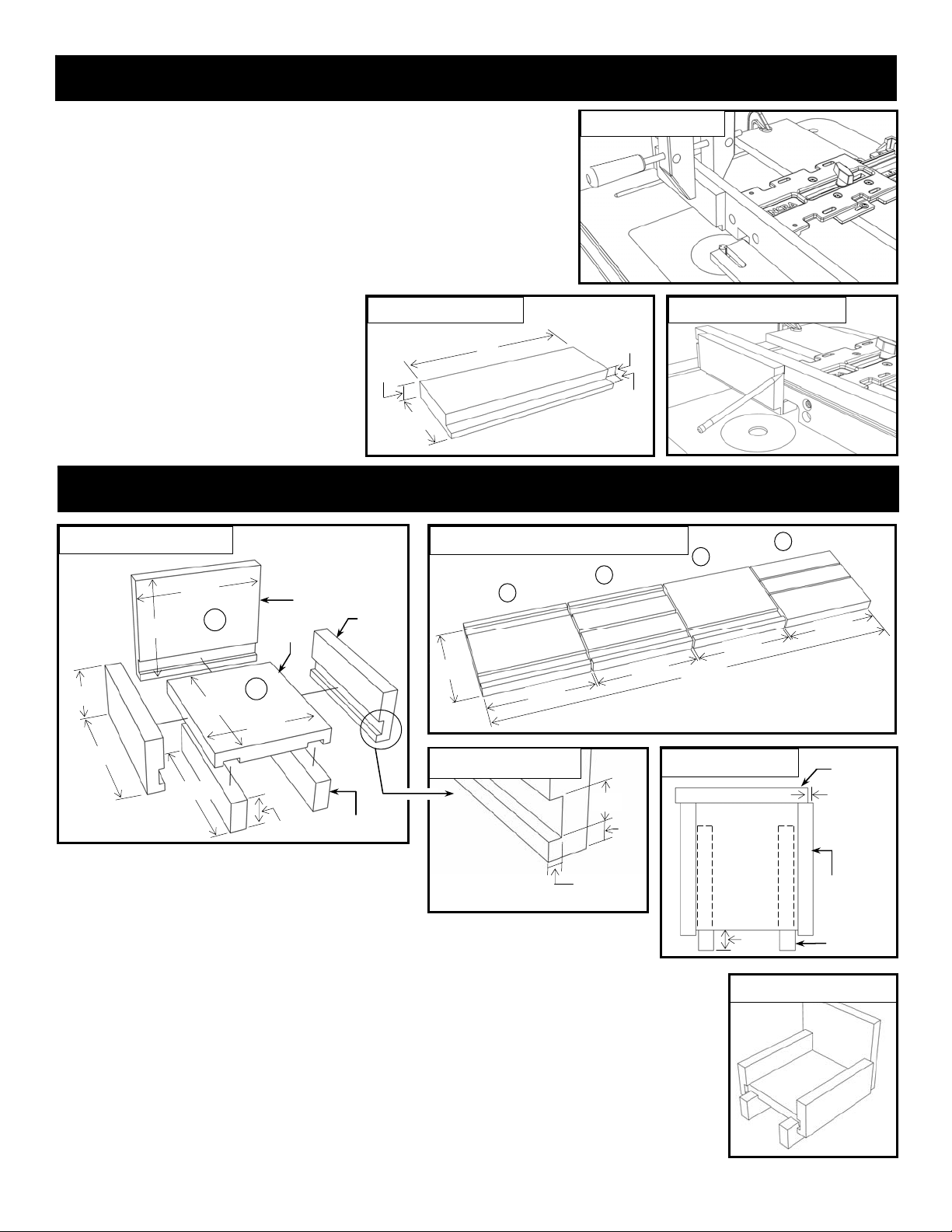
User Made Accessories - Stop
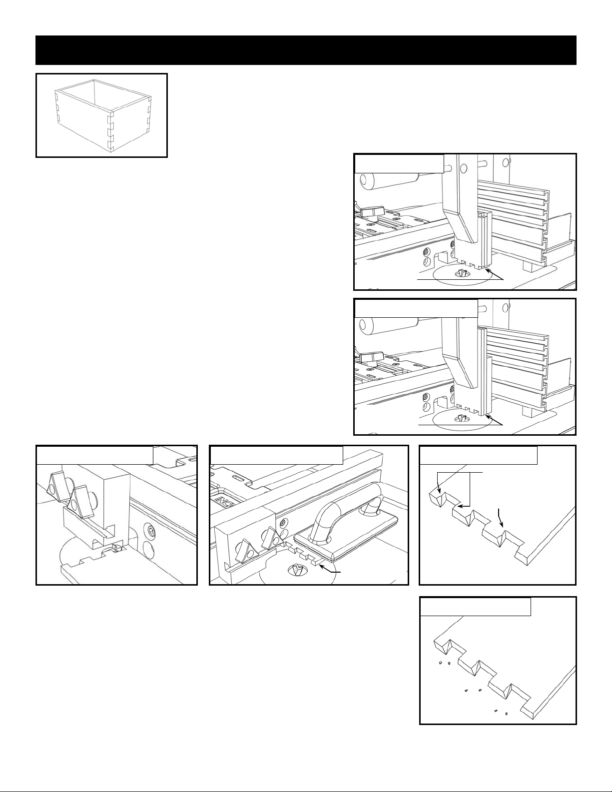
Making a Stop Positioner
Fig. 10
Stop positioner
Your stop positioner is useful for limiting the length of cuts made at the
router table. Just position the stop and secure it to the fence with a
wooden hand screw clamp, Fig 10. This is perfect for the stopped
cuts required for the dovetail pin cuts described in the joinery section of
this manual.
The simple design shown in Fig. 11 includes a rabbeted area that
allows moving the stop over the top of the cutter for very short stopped
cuts. 3/4” MDF will make a good stop material.
TIP: When making fine adjustments
Fig. 11
Stop dimensions
relative to an initial stop position, place a
mark on the front face of the fence along
the leading edge of the stop positioner,
Fig. 12. Now when you loosen the clamp
and slide the stop you can easily gauge
how much you have moved the positioner.
8”
3/4”
3”
1/2”
1/2”
User Made Accessories - Right Angle Fixture
Fig. 13
2 5/8”
Right Angle Fixture
6 1/2”
5 1/2”
6 1/2”
Material:
3/4” MDF
Faceplate
B
Base
Side (2)
Fig. 13A
”
2
/
1
5
A
5 1/2”
Right Angle Fixture cutting diagram
A
A
e
d
i
S
e
s
a
B
”
2
/
1
6
S
e
d
i
/
1
6
Fig. 12
”
2
Marking stop position
B
t
a
l
p
ce
a
F
6
”
8
/
3
6
2
C
r
e
n
n
u
R
r
e
n
n
u
R
e
”
2
/
1
e
t
s
a
W
”
2
/
1
6
6 1/2”
6 1/2”
1 3/8”
Runner (2)
Making a Right Angle Fixture
This simple Right Angle Fixture is an important
accessory for joinery. Use it to guide your material
Fig. 13B
All grooves are 3/4”
wide by 1/4” deep
and located 3/8”
from the material
edge
Groove detail
Fig. 13C
3/4”
3/8”
1/4”
for the vertical cuts required for dovetails and box
joints as shown beginning on page 7.
To make the design shown in Figs. 13 & 14, begin with (4) identical pieces of 3/4”
MDF, cut to 5 1/2” x 6 1/2”. Cut (2) pieces “A”, (1) piece “B” and (1) piece “C” as shown in
Fig 13A. To cut ALL the grooves as shown in Fig. 13B, set a 3/4” diameter router bit to 1/4”
depth of cut, and set the fence-to-bit distance at 3/8”. Check the fit of the material in the
grooves, then fine tune as necessary. Now, rip (1) piece “A” to yield (2) 2 5/8” wide Side
pieces. Then rip the final uncut blank “C” to yield the (2) 1 3/8” Runners.
To assemble, first glue the (2) Runners to the Base, allowing 3/4” of overhang as shown in
Fig. 13C. Now glue the Faceplate and the (2) Sides to the Base. Make sure that the
Faceplate is offset 1/8” from the fence Side piece as shown in Fig. 13C, and that the
Faceplate and the fence Side piece are square to your table top.
4
Top view
Base
3/4”
Fig. 14
Faceplate
1/8”
This Side bears
against fence
Runner (2)
Finished Fixture
Page 5
Right angle fixture operation.
Before clamping a workpiece to your Right Angle Fixture,
always press the fixture against your fence, then
immobilize by clamping it to the table with a spring clamp,
Fig. 15. When positioning the workpiece against the
faceplate, make sure that the edges of the boards are
against the fence and the ends are contacting the table
surface, then clamp in place using a wooden handscrew
clamp.
CAUTION: Do not allow any part of your
hands to hang below the body of the Right
Angle Fixture. Always keep hands well away
from the bit.
Fig. 15
Right angle fixture operation
Avoid contacting wooden
runners with router bit
Third: Position stock against fence and
clamp with a wooden jaw clamp
Second: Immobilize with spring
clamp (acts like a “third hand”)
First: Push Right Angle
Fixture against the fence
TIP: To avoid contacting the wooden runners with the
router bit, clamp your stop to the outfeed end of the fence
to stop the forward travel before contact.
Basic Operation and Calibration
Note: All subsequent illustrations
reflect use of the factory accessories.
Basic INCRA Jig operation
To move your INCRA Jig’s fence from one scale setting to
another, loosen the clamping knob two full turns and lift the
rear of the INCRA Jig’s upper body. This disengages the
saw-toothed racks and allows you to slide the Jig forward.
Slide to align the rear of the upper body over the desired
mark on the scale, then lower the upper body to re-engage
the racks. You should be able to shift the upper body from
side to side easily when the racks are engaged properly.
Tighten the clamping knob, Fig 16.
TIP: A wooden jaw clamp works BEST! One-handed
clamps typically don’t have enough holding power, and a
C-clamp can mar your work, and can be difficult to handle.
Fig. 16
Second: Lift back
end of upper body
Basic operation
First: Loosen clamping
knob 2 full turns
Fourth: Lower body then
tighten clamping knob
Third: Slide upper body to desired
alignment over scales
INCRA Jig calibration
Initially, the alignment between the scale and body may
appear slightly off, but the one-time-only adjustment is
easy. Loosen the four Phillips head screws that secure the
upper racks, then loosen the clamping knob about one-half
turn. Now shift the upper body slightly forward or
backward until the rear of the upper body aligns clearly
over any scale mark. Tighten the clamping knob, then
secure the racks by re-tightening all four Phillips head
screws, Fig. 17. From now on, the scale will align perfectly
at all INCRA Jig settings.
Fig. 17
First: Loosen all (4)
5
Calibration
Phillips screws
Second: Loosen clamping
knob 1/2 turn
Third: Shift upper body until desired
alignment over scales is achieved
Fourth: Tighten
clamping knob
Fifth: Tighten all (4)
Phillips screws
Page 6

Applications - Common Cuts
Grooving, dadoing, rabbeting and edge forming.
Box joints, dovetails and the exotic INCRA Double and Double-Double joinery may be the icing on the
cake, but everyday cutting applications such as grooving, dadoing, rabbeting and edge forming are the
real bread and butter benefits of owning an INCRA Jig. Each of these common cutting operations requires
a different way of calibrating the fence to the
cutter. For grooving and dadoing, you will
typically zero the fence to the INSIDE edge
of the router bit. For rabbeting, you will zero
the fence to the OUTSIDE edge of the bit.
And for edge forming, you will often add a
pair of sub fences to accommodate the
larger diameter of most edge forming bits.
A quick look at the illustrations below will
show how you can quickly and easily
calibrate your INCRA Jig for each of these
types of cuts.
Fig. 18
Grooving and dadoing
Fig. 19
Fig. 19A
Zeroing for grooving and dadoing
First: Lock upper body at 0”
Third: While continuing to nudge
Second: loosen clamps and
slide base panel forward
towards the cutter
the base panel forward, sight
along the fence until the gap of
light between the fence and the
cutter disappears.
Fourth: Re-tighten the base
panel clamps. The fence is
now zeroed to the inside edge
When setting up for most common cutting
operations, the first step us usually to set
the INCRA Jig to a reading of zero, as
shown in Fig. 19A. The base panel is
then moved forward until the fence is
“zeroed” to the desired edge of the bit.
of the cutter
Fig. 20
Fig. 22
Rabbeting
Edge forming
Fig. 21
First: Lock upper
body at 0”
Fig. 23
Zeroing for rabbeting
Zeroing for edge forming
First: Lock upper
body at 0”
Second: Loosen clamps and slide base panel
forward until the fence covers the cutter
Third: Hold straight-edge
against fence
Fourth: Tap base panel
backward until cutter “kisses”
the straight-edge
Fifth: Re-tighten the base panel clamps.
The fence is now zeroed to the outside
edge of the cutter
Second: Loosen clamps and slide base panel
forward until sub fences cover the cutter
Third: Hold straight-edge
against fence at level of
cutter bearing
Fourth: Tap base panel
backward until bearing
touches straight-edge
Fifth: Re-tighten the base panel
clamps. The fence is now zeroed to
the cutter bearing
6
Page 7

Applications - Joinery
Joinery represents one of the most exciting applications
for your new INCRA Jig. Just by applying a little technique
to the extreme accuracy built into your INCRA Jig, you’ll
soon be able to add joinery for box and drawer making to
your list of shop skills. The two included templates will
allow you to produce 3/8” box joints and 1/2” Sliding, Half
Blind, Through and Corner Post Dovetails. The included
variations technique will allow you to produce dozens of
pattern variations on each of the four joint types.
We’ll begin with a look at two simple, but important setup
operations that must take place before using your INCRA
Jig for joint making at the router table. They are:
1. Setting the router bit depth of cut.
2. Centering the bit on your workpiece and
installing the template.
Set the router bit depth of cut for Box Joints
After installing the appropriate diameter straight bit for the
template pattern selected (3/8” for the included template),
simply raise or lower the bit to set the depth of cut at slightly
greater than the thickness of the stock you will be cutting.
See Fig. 24.
TIP: When making box joints, use a stock thickness equal
to the diameter of the straight bit used to cut the joint.
For even more variety,
including Double Dovetails
and Double-Double Box
Joints, the optional Master
Reference Guide and
Template Library contains a
large selection of new
joinery templates. While
designed for the larger 16”
Ultra and LS Positioner
models, the templates can
be cut to length to fit your
New INCRA Jig to provide an
impressive array of styles
and joint types for your
projects.
Fig. 24
Depth of cut - Box Joints
Raise or lower the bit to
slightly greater than the
thickness of your stock
B
Board to be joined
d
r
a
o
b
f
o
d
u
o
r
p
t
s
u
j
t
i
Set the router bit depth of cut for Dovetails
As with any dovetail jig, the depth of cut of your dovetail
bit will determine whether your joint is too loose, too tight,
or just right. Just a little practice using the following steps
will ensure that your dovetail joints will always fit perfectly.
Install the dovetail bit recommended for your template
selection and adjust the bit height to the approximate
depth of cut suggested under the joint diagram for that
cutter, (1/4” for the 1/2”-14
o
bit or 3/8” for the 1/2”-10o bit.)
Set the INCRA Jig to zero on the scale and tighten the
clamping knob. Then loosen the base panel clamps and
slide the unit forward until the fence covers about half of
the bit, then re-tighten the clamps, Fig. 25.
Test cuts for setting the depth of cut
Clamp two pieces of square cut stock to your Right Angle
Fixture and make a cut at the zero setting. Move the
fence back to a scale reading equal to the “Spacing to
Set Depth of Cut” listed under the diagram for the
selected template (7/8” for the included template) and
tighten the clamping knob. Now, make a second cut on
your stock as shown in Fig. 26.
Fig. 25
Fourth: Re-tighten clamps
Second: Lock upper body to “0”
Fig. 26
Depth of cut - Dovetails
Dovetail test cuts
First: Clamp two boards to
Right Angle Fixture
Second: Make first cut
at “0” setting.
Third: Loosen clamps and slide base
panel forward until fence covers
about half of the cutter
First: Set bit height to
recommended approximate depth
of cut shown on page 16
Third: Move fence back to dimension listed under
“Spacing to Set Depth of Cut” in pattern design
(7/8” for included dovetail template ). Then make
the second cut
7
Page 8

Unclamp the two boards and test the fit by joining them as
shown in Fig. 27. As with any dovetail jig, a little trial and
error is needed to achieve a snug fitting joint. To tighten
the fit, raise the bit up slightly; to loosen the fit, lower the
bit slightly. Just remember this phrase: “Heighten to
tighten, lower to loosen”. After adjusting the bit height,
make a new set of trial cuts on a fresh uncut corner of the
boards. After a few adjustments and trial cuts, you’ll have
a perfect fit.
Tip: When the fit is too loose, the trial cuts provide a
gauge to let you know how much to raise the bit. Just join
the trial pieces end to end and gently pull the boards to
wedge the dovetails apart, Fig. 27. The gap that appears
is equal to the distance you need to raise your dovetail bit
to achieve a tight fit, Fig. 28.
Heighten to tighten
Or
Lower to loosen
Fig. 27
Gap
Fit is too loose
Fig. 28
Perfect fit
Raise the bit
this much . . .
. . . to produce a
perfect fit
Centering the router bit on your workpiece
Rout a test groove
NOTE: The following instructions apply to Dovetails AND Box Joints.
After setting your router bit depth of cut, you will position your INCRA Jig and
install the joinery template. This is accomplished through a setup operation
called “centering”. Centering locates your INCRA Jig so that the router bit is
aligned with the center of the stock width you select. Once you find the center,
install the joinery template and you’ll be ready to cut a perfect joint. The simple
steps to follow should always be used when setting up for joint making.
Begin by cutting a piece of 3/4” thick stock to the same
width as the boards you wish to join later on. Mark the
center of this board’s width on one end and place the
board face down on the router table with the
center of the board aligned with the
approximate center of the bit, Fig. 29.
First: Lock upper
body to 3”
Set your INCRA Jig to 3” on the scale and
tighten the clamping knob. Then loosen the
Fig. 30A
clamps that secure the base panel, and slide
it forward until the fence contacts the edge of
the board. Make sure the center mark on the
board is still aligned with the approximate
center of the bit, then re-tighten the clamps,
Figs. 30 and 30A.
Fig. 30
Set initial fence position
Fig. 29
Align center of board with
approximate center of bit
Align board with bit
Second: Loosen clamps and slide base
3/4” stock
panel forward until fence contacts
edge of centering board
Turn the router on, and using a good rubber
soled push block, cut a groove along the
entire length of the board, Fig. 31. Now turn the stock end
for end and make a second pass over the router bit. The
second pass should widen the groove slightly (unless you
are already perfectly centered). Make sure you have turned
the stock end for end before making the second pass. (This
places the center mark at the back of the board.)
With the router off, turn the cutter to it’s widest profile. Slide
the test board against the fence to rest just over the cutter.
There should be a
small gap between
Fig. 32
the edge of the bit
and one side of the
groove, Fig. 32.
Small gap on one
side of the bit
Fig. 31
First: Rout a groove along the
entire length of the stock
8
Rout test groove
Second: Rotate board end-
for-end and make a second
pass over the bit
Page 9

Fine-tune fence position and install template
To center the router bit on the test board, loosen the clamps
that secure the base panel to your router table. As you hold
the board against the fence, tap the base until you see an
equal gap on both sides of the cutter, Figs. 33 & 34. If your
test piece is thick enough, you can flip it over and repeat the
test cuts to confirm that the cutter is centered on the board.
Once you are familiar with the process, one set of test cuts
should do it.
Now that you have found the center of your board, you can
install the joinery template. Place a piece of template tape
to overlap the right side of the template near the end. Slide
the template into the receiving slot and align the mark
representing the suggested center cut with the end of the
INCRA Jig’s upper body. You’ll find the suggested center
cut listed under the diagram of each template pattern on
page 16. Hold the template in place as you press the
template tape to the lower body, Detail 33A.
TIP: Common cellophane tape works great too.
Fig. 34
Center board over bit
Now, let’s do
some joinery.
Equal gap on both sides of cutter
Fig. 33
Second: Loosen clamps and slide
base panel until you see an equal
gap on both sides of the cutter
First: Hold centering
Align board with bit and install template
(see Fig. 34)
board to fence
Fig. 33A
Third: Slide template
(lower numbers first) into
receiving channel.
Fourth: Align suggested “Center Cut” mark
with rear of upper INCRA Jig body
Note: Template numbers
increase towards the back
of the INCRA Jig
Fifth: Adhere template with a
piece of template tape
Half Blind Dovetails
Half Blind Dovetails
The easiest of the dovetail joints, half blind dovetails, add strength and
beauty to your projects. They are also the most versatile of the many
joints you can cut with your INCRA Jig. In fact, many of the decorative
joints we’ve designed over the years are just variations on the half blind
technique you are about to learn. Once you’ve mastered the steps
below, you’ll find these decorative joints (the Corner Post Dovetail on
Half blind dovetails
Install the template
After centering as shown on Pages 8 & 9, select and install the
Dovetail Template. (Refer to Page 16 and Figs. 33 & 33A).
Determine joint layout (pins or tails?)
The first step in making ANY dovetail, whether it be Half
Blind, Sliding, Through or Corner Post is to decide which
half of the joint will be the pins and which half will be the
tails. Refer to the instructions in Figs. 61 and 62 on page
14 to determine which series of cuts to use for each half of
the joint.
Cut the Tails
To cut the tails for a half blind dovetail, begin by cutting a
dovetail shaped rabbet on both ends of the two boards, Fig 35. The rabbet should be 7/32” wide as shown in Fig. 35A.
Don’t cut the full rabbet in a single pass. Instead, start with a light 1/32” scoring pass then use three or four light side by
side passes to sneak up on the final rabbet width. You can use the 1/32” scale in your INCRA Jig as a reference so
you’ll know how much you have widened the rabbet with each pass.
page 11 and the Double Dovetail in the optional Master Reference
Guide and Template Library) quite easy to complete.
Cut dovetail shaped rabbets
7/32”
Rout dovetail shaped
rabbet cuts on both ends
of the tail boards
Fig. 35A
9
Fig. 35
Rabbet width
Page 10

Tail Cuts - Continued
Now, clamp the two tail boards to your Right Angle
Fixture as shown in Fig. 36 and make the tail series of
cuts. The first cut for any tail board will always remove
the edge of the stock. To keep this first cut clean and
splinter-free, it’s a good idea to return to a 1/32” scoring
pass, then sneak up to the first visible mark on the
template in one or two passes. The first visible mark
determines which cut lines to use on the template for the
remainder of the tail cuts. If the first mark is a “B” cut for
example, simply move the INCRA Jig from one “B” cut to
the next “B” cut until you have cut across the full width of
your material. After completing the cuts, flip the boards
end for end and repeat.
Fig. 36
Cut the tails
Handscrew clamp
Fence
Right angle fixture
Clamp two tail boards
with rabbets facing
outward as shown
Pin Cuts
Move the INCRA Jig to the first pin cut on the template that will position the
cutter outside the fence. Since the pin sockets are stopped cuts, bring the
stop positioner just up to the outside diameter of the cutter and clamp in
place, Fig. 37. This stop setup will always (and intentionally) produce a
socket that is just a little short, so we’ll only cut one end of one piece
at this time, then adjust as necessary. Using a rubber soled push
block, move the stock into the cut until you just touch the stop. Don’t
force the material against the stop. Now move the fence from one pin
cut to the next until you have cut across the full width of your material, Fig.
38. After making the cuts, check the fit between this board and one of the
tail boards. Adjust
the stop position
Fig. 38
Pin cuts - final
as necessary to
control the socket
length for a
perfect, flush fit
(See Tip and Fig.
38A at right).
Now make the
final pin cuts on
both ends of both
boards.
Position stop as close as
possible to the outfeed
Stop positioner
side of the bit
Fig. 37
Set stop positioner
Tip: After making your first series of
pin cuts, check the fit with one of your
tail boards. If the tail board won’t fit
all the way into the pin board, just
measure the distance it protrudes,
Fig 38A. This is the distance you
need to move the stop away from the
bit to achieve a flush fit.
Fig. 38A
Pin cuts - final adjustment
Pin board
Beginner’s Tip
After making a half blind dovetail, you may notice that the joint looks
symmetrical, but the edges of the two boards do not align flush, Fig. 39. This
simply means that when you centered your material as described on page 8,
you were close but not quite perfect. Of
course practice DOES make perfect, but
there is another method for cutting the tail
boards that will ensure a flush alignment
regardless of how well your board was
centered. Just make sure when you clamp
the tail boards to the Right Angle Fixture
that the dovetail shaped rabbets on all of
the boards face the cutter, Fig. 40. That’s
all it takes! Remember that even if you use
this procedure, you should still center first to
ensure a symmetrical looking joint.
Fig. 39
Tail cuts - beginner’s tip
Boards not flush
10
Tail board
Move stop block this far back
to achieve a flush fit
Fig. 40
Dovetail shaped rabbets face cutter
Page 11

Corner Post Dovetail
Corner Post Dovetails
The Corner Post Dovetail is a beautiful and deceptively simple variation on
the half blind technique that you have just learned. If you have mastered
the half blind, then you have already just about mastered the Corner Post.
In fact, in the final series of cuts, you will join four boards together using the
exact same steps used to produce a half blind. If you have not made a half
blind joint yet, you should go back to Page 9 to review that section before
continuing. Now, let’s take a stepby-step look at this beautiful
Corner post dovetails
Stock requirements
For this decorative joint, you’ll need the same four pieces required for any
half blind joint (two short pieces and two long pieces) plus a piece of
contrasting color stock about 8” long to make the corner post. All should be
the same thickness and width, Fig. 41. Since this joint is based on half
blind techniques, the stock thickness must be greater than your depth of cut.
Make the long sides for corner posts
After centering (page 8), set the fence to a scoring pass position and
tighten the clamping knob. Clamp the two long boards, along with a
backing board to the Right Angle Fixture. Starting with a scoring cut,
advance to the first visible mark on the template in one or two passes.
The first visible mark determines which cut lines to use on the template
for the remainder of the cuts. If the first mark is a “B” cut for example,
simply move the INCRA Jig from one “B” cut to the next “B” cut until you
have cut across the full width of your material. After completing the
cuts, flip the boards end for end and repeat the cuts, Fig. 42.
Corner Post joint.
Fig. 42
Fig. 41
(2) short pieces
(2) long pieces
The bottom piece is 8” long and is
Stock requirements
a contrasting color
Cut long sides
All (5) pieces are
equal in width and
thickness.
Make the corner posts
To make the corner posts, set the INCRA Jig to the first mark on the
template that exposes the cutter in front of the fence, then tighten the
clamping knob. If you used a “B” cut on the previous series of cuts,
then the corner post series will be the “A” cuts and visa versa. Using a
rubber soled push block, cut a groove through the entire length of the
corner post piece. Now move the fence from one mark to the next to
cut the grooves across the full width of the corner post piece, Fig. 43.
At your table saw, use a miter gauge with a wooden auxiliary fence to
crosscut the corner post stock. Fig 44. You’ll need four corner post
pieces per box. Each piece should be about 1/16” longer than the
thickness of your box side material to allow for flush belt sanding later
on.
Glue the corner posts to the side pieces
Use a brush to apply glue to two of the corner post pieces, then apply
glue to both ends of the mating box side. Slide the corner post pieces
onto each end of the box side and center so that the corner post
overhangs each face of the larger piece slightly. We’ll sand them flush
later. Place scrap wood clamping
pads at each end and clamp. Wipe
off excess glue squeeze out and set
aside. Repeat the glue-up
procedure for the remaining pieces
and set aside to dry for about 30
minutes, Fig 45. Unclamp and belt
sand the corner post sections flush
with the faces of the two boards.
Fig. 45
Glue corner
post pieces
11
Fig. 43
Fig. 44
Clamp two long sides with backing
board to Right Angle Fixture
Rout corner post blank
Rout grooves along full length of blank
Cross cut corner post pieces
Page 12

Corner Post Tail Cuts
From this point forward all we are doing is using standard
half blind dovetail techniques to join the four rectangles of
wood. Here is a quick review.
Use the remaining short pieces of your material for the
tails. To cut the tail boards, we’ll begin with the dovetail
shaped rabbets. Move the INCRA Jig to a scoring pass
position and tighten the
clamping knob. Make the
scoring pass across both ends
of both pieces. Increase the
full rabbet width to 7/32” with
three subsequent passes,
moving the fence back 1/16”
for each cut, Fig. 46 and
Detail 46A.
Fig. 46A
Rabbet width
7/32”
Fig. 46
Cut dovetail shaped rabbets
Rout dovetail shaped
rabbet cuts on both ends
of the tail boards
Now, clamp the two tail boards to your Right Angle
Fixture as shown in Fig. 47 and make the tail series of
cuts. The first cut for any tail board will always remove
the edge of the stock. To keep this first cut clean and
splinter-free, it’s a good idea to return to a 1/32” scoring
pass, then sneak up to the first visible mark on the
template in one or two passes. Make the tail series of
cuts across the width of your material. After completing
the cuts, flip the boards end-for-end and repeat the cuts.
Corner Post Pin Cuts
Slide the stop positioner just up to the outside diameter of
the cutter and clamp in place, Fig. 48. This stop setup will
always produce a socket that is a little short, so cut one
end of one piece at this time, then adjust the stop position
as necessary before making the final cuts on both ends of
both pieces. See the tip on page 4 for more information on
Fig. 48
Set stop positioner
Fig. 49
Fig. 47
Cut the tails
Handscrew clamp
Fence
Right angle fixture
Clamp two tail boards
with rabbets facing
outward as shown
adjusting the stop position. Remember, if you used the “B”
cuts when cutting the tails, you’ll use the “A” cuts for the
pins and visa versa, Fig. 49. After completing the pin cuts,
assemble both pin boards to one of the tails, then add the
other tail board and drive the tails home. Try this
spectacular joint on your next jewelry box project.
Pin cuts - final
Stop positioner
Position stop as close as
possible to the outfeed
side of the bit
Fig. 50
Completed Corner Post
At this point, you can cut the
pins just like you would on any
other half blind dovetail (see
page 10)
12
Page 13
Through Dovetail
Through Dovetails
When preparing stock for a through dovetail, always remember that the stock thickness
must be equal to or slightly less than the depth of cut. It is a good idea to FIRST set your
router bit depth of cut as described on page 7 before preparing your stock, since you must
make the stock match the cutter depth. You cannot raise or lower the cutter to match your
stock thickness! Follow the instructions below to add this traditional interlocking joint to
Through dovetails
Install the template
After centering as shown on Pages 8 & 9, select and install the
Dovetail Template. (Refer to Page 16 and Figs. 33 & 33A).
Tail Cuts
Clamp the two tail boards to your Right Angle Fixture with a backing
board as shown in Fig. 51 and make the tail series of cuts. Use the
shorter of your stock lengths for the tails. The first cut for any tail
board will always remove the edge of the stock. To keep this first cut
clean and splinter-free, it’s a good idea to start with a 1/32” scoring
pass, then sneak up to the first visible mark on the template in one or
two passes. The first visible mark determines which cut lines to use
on the template for the remainder of the tail cuts. Make the tail series
of cuts across the width of your material. After completing the cuts,
flip the boards end for end and repeat the cuts.
your skills resume.
Fig. 51
Two SHORT sides
with backing board
Fig. 52
Cut the tails
Pin cuts - vertical series
Pin Cuts
After completing the tail cuts, clamp the two long pieces of material to
the Right Angle Fixture with a backing board as shown in Fig. 52 and
make the vertical series of cuts for your pin boards. Remember, if you
used the “B” cuts when cutting the tails, you’ll use the “A” cuts for the
pins and visa versa. After completing the cuts across one end of your
boards, flip the material over and repeat the vertical pin series of cuts.
Fig. 53
Now, we’ll repeat the pin series of cuts again. This time with the material face down
on the table. Return your INCRA Jig to the first pin cut on the template. With the
router off, slide one of the pieces to nest the cutter inside the existing cut. You need
to stop the cut just before the cutter contacts the end of the existing cut. Slide a stop
positioner up to the end of the board and clamp in place, Fig. 53. Slide the board
back away from the cutter, turn the router on and using a rubber soled push block,
make the horizontal pin series of cuts on both ends of both boards, Fig. 54.
Pin cuts - set the stop
Fig. 54
Pin cuts - horizontal series
Two LONG sides with
backing board
See detail in Fig. 55
Fig. 55
Fig. 56
Pin cuts - remove tabs
Whittle off these triangles of
wood from each pin.
Cut straight back to corner
Completed pin cuts
If you try to assemble your pin and tail pieces at this moment, you would find that a
small triangle of wood blocks the two pieces from sliding together. To complete the
joint, all that you need to do is whittle off this triangle of wood. This can be
accomplished with a pocket knife, a razor knife or a chisel. Just follow the line of the
cut that was started straight back into the corner, Figs. 55 and 56. Now assemble for
a perfect through dovetail.
13
Page 14

Determine dovetail joint layout.
The first step in making ANY dovetail joint, whether it
be Half Blind, Sliding, Through or Corner Post is to
determine which half of the joint will be the pins and
which half will be the tails. Follow the instructions in
Figs. 61 and 62 to decide which series of template
cuts to use for each half.
Fig. 62
Board to be cut
Determine joint layout
Pins (solid wood on ends)
C
Center of board is
L
aligned with “Center
Cut” on template.
Fig. 61
Tail boards are always cut vertically,
clamped to the Right Angle Fixture
and have “open cuts” on the outside
Pins or tails?
edges.
Pin boards are cut horizontally and will
always have partial pins (solid wood) on the
outer edges of the boards
1
/
8
”
Dovetail Variations
The drawings at right show several
variations on a standard equally spaced
dovetail joint. Although these joint
patterns look quite different from one
another, they all have one thing in
common. They are all made using the
same equally spaced dovetail template.
By learning the variations technique
described below, you can customize the
joint pattern produced by any template.
This technique works not only for Half
Blind dovetails as pictured, but also for
Box Joints, Through Dovetails and even
the Corner Post Dovetails. In general,
pattern variations can be designed by
observing a few simple rules.
Tails (open cuts on ends)
Suggested Center Cut is 5A
To determine pins and tails, align the center of the board with cut “5A” on the dovetail diagram on
page 16 and observe where the edges overlap the full scale joint diagram. This will determine which
series of cuts will be the pins, and which will be tails. Pins have solid wood on the outside edges, and
m
i
n
i
m
u
m
Fig. 57
tails have mating open cuts on the outside edges. In this example, the pins are the “A” series and
the tails are the “B” series of cuts. Pins and tails are determined entirely by the width of the board.
IMPORTANT: Avoid just a “sliver” of solid wood on the outside edges of the pins. If necessary, use
a slightly wider board to allow at least 1/8” of solid wood on both edges of the pins.
Fig. 58 Fig. 59 Fig. 60
Pin and tail board characteristics
Fig. 61 details the characteristics of a common pin and tail
board. This information is useful in trying to visualize a
pattern modification using the variations technique.
Select cuts to omit
Variations are created by OMITTING cuts on one half of
the joint, and then ADDING them to the other half of the
joint. Layout the board on the full scale dovetail pattern on
page 16 to help you decide whether to omit cuts from the
pins or the tails. Leaving cuts off of the tail side, for
example, creates wider tails, Fig. 58. Leaving cuts off of
the pin side creates wider pins, Fig. 59. Although a bit
more complicated, cuts can be left off of both sides of the
diagram, resulting in a pattern variation that has both wider
pins and wider tails, Fig. 60.
Always modify the pattern symmetrically
For example, if you decide to omit the first two “A” cuts on
your stock’s width, you should also omit the last two “A”
cuts.
Cut the joint
Any cuts omitted from one half of the joint will be used to
modify the other half of the joint. If you decide, for
example, to omit cuts 2A and 7A when you are cutting the
“A” series of cuts on the first half of the joint, JUST ADD
cuts 2A and 7A to all of the “B” series of cuts on the
second half of the joint to automatically produce the proper
mating fit. It’s really that simple, give it a try sometime.
Dozens of pattern variations are possible for each joint
type.
14
Page 15

Box Joints
Box Joints
This simple but effective interlocking joint technique is the easiest of all. You’ll
cut your material two pieces at a time with a backing board, using the “A” cuts
for two of the boards and the “B” cuts for the other two.
Let’s get started.
Box joint
Install the template
After centering as shown on Pages 8 & 9, select and install the
Box Joint Template. (Refer to Page 16 and Figs. 33 & 33A).
Clamp two pieces of your stock to the Right Angle Fixture with a
backing board as shown in Fig. 63. Begin with a scoring pass,
then advance to the first visible mark on the template in one or two
passes. The first visible mark determines which cut lines to use on
the template for the remainder of the cuts on these two boards. If
the first mark is a “B” cut for example, simply move the INCRA Jig
from “B” cut to “B” cut until you have cut across the full width of
your material. After completing the cuts, flip the boards end for
end and repeat the cuts.
Now clamp the final two boards to the Right Angle Fixture with a
backing board as shown in Fig. 64 and make the alternate series
of cuts remaining on the template on both ends of your boards.
Fig. 63 First series of cuts
Fig. 64 Second series of cuts
Maintenance
Keeping the saw-toothed racks on your INCRA Jig clean of debris and sawdust is all that is necessary to keep the unit in
top shape. Occasionally remove the clamping knob and blow out the racks. An old toothbrush is a great tool to remove
embedded sawdust and chips. An occasional spray of dry lubricant on the threads of the clamping knob and carriage
bolt will make it easier to clamp and unclamp.
WARRANTY
Taylor Design Group, Inc. warrants this product for one year from date of purchase. We will repair any defects due to
faulty material or workmanship, or at our option, replace the product free of charge. Please return the failing component
only, postage prepaid, along with a description of the problem to the address below. This warranty does not apply to
parts that have been subjected to improper use, alteration or abuse.
LIFETIME WARRANTY ON POSITIONING RACKS
If an INCRA positioning rack in this tool becomes damaged for ANY reason, Taylor Design Group will replace it free of
charge for as long as you own your tool. Return the damaged rack, postage prepaid, and allow 1 to 2 weeks for delivery.
NOTE: Replacements cannot be sent unless damaged racks have been received by Taylor Design Group, Inc.
Made in America by:
Taylor Design Group, Inc.
PO Box 810262
www.incra.com
INCRA Products are protected by the following US Patents: #4,793,604, #4,930,221, #5,195,730, #5,725,074, #5,423,360, #5,716,045, #6,237,457, #6,557,601, #6,672,190
2005 by Taylor Design Group, Inc. Printed in the U.S.A. INCRA is a registered trademark of Taylor Design Group, Inc.
©
Other patents granted or pending.
Dallas, TX 75381
Phone: 972-242-9975
15
Page 16

3/8” Box Joint Template
Suggested Center Cut: 6B
Template Identification: Notch punched in this end
1/2” Dovetail Template
Suggested Center Cut: 5A
Approximate Rabbet Width: 7/32”
Spacing to Set Depth of Cut: 7/8”
Template Identification: This end NOT PUNCHED
Depth of Cut Chart
16
16
 Loading...