

Page 1
SAFETY
SAFETY
CONTENTS
CONTENTS
❒ When adjusting the fence opening, never
position the infeed or outfeed fence ends
closer than
1
/8" from the router bit.
❒ After making adjustments to the fence
positions, be sure to tighten the two socket
head cap screws through the large holes in
both the infeed and outfeed fences.
❒ When using fence settings in which the router
bit is partially recessed in the fence opening,
always insure that the bit is centered within
the opening.
❒ Never let the router bit come into contact with
the aluminum body of the INCRA Intelli-Fence
or INCRA Stop.
❒ Whenever using large diameter vertical or
horizontal panel raising bits or any other
large diameter bit, always follow that router
bit manufacturer’s operation and safety
recommendations.
❒ Whenever it is necessary to remove large
amounts of stock, always use multiple side
by side passes to achieve the final cut.
Several shallow cuts are safer and will
yield better results.
Please read this owner’s
manual before use and
keep it at hand for
reference.
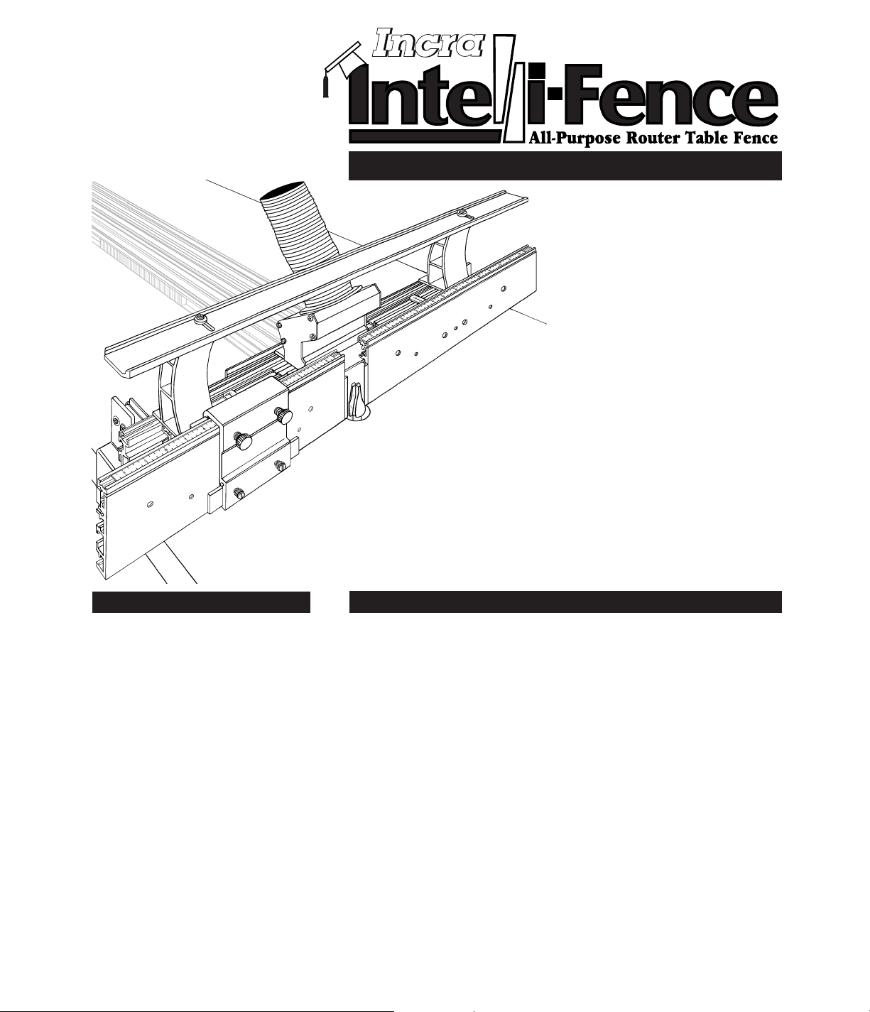
The micro adjustable split fence design of
the INCRA Intelli-Fence
™
provides access
to many operations previously reserved
for specialty machines. From the straight
edge cutting abilities of the jointer to the
many edge forming functions performed
by the shaper, your new Intelli-Fence
offers a host of exciting new possibilities
for your router and shaper table.
It all starts with intelligent design
features. The opposing wedge design of
the infeed/outfeed offset mechanisms
permits very fine continuous adjustment of
the fence offset from zero to
1
/8", and each
offset mechanism has its own hairline
cursor and scale marked off in
2
/1000 of an
inch increments. Position the fences
“in-line” for typical router table fence
operations, and with the included table
clamps, you can use the Intelli-Fence in
the freestanding mode. Or, you can mount
it directly to your INCRA Jig Ultra or Pro
for the ultimate router table fence setup.
It’s completely compatible with all INCRA
joint-making accessories. The unique
Hi-Rise
™
fence cap and an adjustable
fence opening take the hassle out of
working with large panels and large router
bits for panel raising operations. All these
features combined with the patented
INCRA Stop and a universal dust
collection port make the INCRA
Intelli-Fence the intelligent choice for
your router or shaper table.
OWNER’S MANUAL
®
Assembly . . . . . . . . . . . . . . . . . . . . . . . . 2
Mounting to your Router Table. . . . . . . . 3
Attaching to your INCRA Jig . . . . . . . . . 3
Freestanding Mode . . . . . . . . . . . . . . . . 3
Operation . . . . . . . . . . . . . . . . . . . . . . . . 4
Offset Adjustment . . . . . . . . . . . . . . . . . 4
Gap Adjustment . . . . . . . . . . . . . . . . . . 5
Initial Fence and Scale Setup . . . . . . . . 5
Fence Bridge Adjustment . . . . . . . . . . . 6
INCRA Stop . . . . . . . . . . . . . . . . . . . . . 6
In-line Fence Applications . . . . . . . . . . . 6
Vertical Panel Raising. . . . . . . . . . . . . . 6
Joint Making . . . . . . . . . . . . . . . . . . . . . 7
Offset Fence Applications . . . . . . . . . . . 7
Jointing. . . . . . . . . . . . . . . . . . . . . . . . . 7
Shaping . . . . . . . . . . . . . . . . . . . . . . . . 8
Product Information. . . . . . . . . . . . . . . . 8
Warranty . . . . . . . . . . . . . . . . . . . . . . . . . 8
Important safety instructions for using the INCRA Intelli-Fence:
❒ Before using the INCRA Intelli-Fence, read
and follow all of the instructions and safety
information in this manual.
❒ When using the INCRA Intelli-Fence in
conjunction with any other tool, first read
and follow all instructions and safety
information in that tool’s owner’s manual.
❒ Use appropriate safety devices. Always
use a push stick, rubber soled push block,
or other safety devices to keep your hands
safely away from the cutting tool.
❒ When used in the freestanding mode with
the supplied table clamps, always make
sure the clamping knobs are tightened
securely in place before making any cuts.
❒ If attaching the INCRA Intelli-Fence to your
INCRA Jig Ultra or Pro, always make sure
the carriage clamp on the INCRA Jig is in
the locked position and the base is held
securely in place before making any cuts.
❒ Always turn off the power and make sure
that the router bit has come to a complete
stop before changing the setting of any part
of the INCRA Intelli-Fence or INCRA Stop.
From the makers of
INCRA JIG!
• Split fence design
• Micro adjustable
• Universal dust collection port
• Adjustable fence gap
• Compatible with all INCRA
joint-making accessories
Page 2
Second: Position inner rack 1" from outer racks
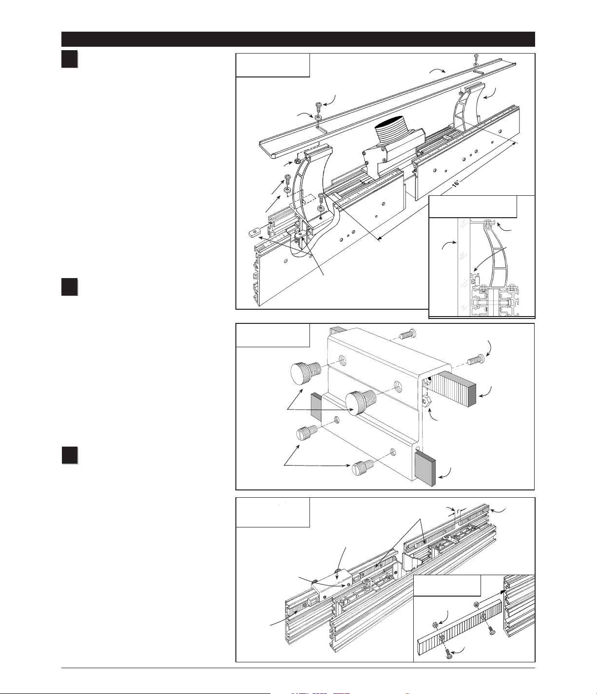
Attach Hi-Rise fence cap
Attach the two Hi-Rise fence cap braces
using (2) #10-32 x
3
/8" phillips pan head
screws, #10 washers and #10-32 rectangular
nuts. See Fig.1. Loosely attach the
rectangular nuts to the screws then slide the
nuts into the two T-slots provided.See Fig 1A.
The two braces should be approximately
centered on the length of the fences and
spaced 16" apart.
Using the (2) #10-32 x
1
/2" phillips pan head
screws,
5
/8" o.d. nylon washers, and #10-32
hex nuts, attach the Hi-Rise fence cap to the
two braces as shown in Fig. 1 The slotted
holes in the fence cap should be aligned to
provide access through the slots to the front
brace mounting screws.Use a straight edge
to align the leading edge of the fence cap
with the front face of the infeed and outfeed
fences and tighten the two cap mounting
screws, Fig. 1A.
Assemble INCRA Stop
Using the (2) #8-32 x 3/8" phillips pan
head screws and #8-32 hex nuts, fasten one
of the blue INCRA racks to the INCRA Stop
and tighten the screws. See Fig. 2. Slide the
3
/4" x 5" plastic strip into the slot in the stop
and secure with two
1
/4-20 x 1/2" nylon
thumbscrews. Thread the (2)
3
/8-16 x 1/2"
nylon thumbscrews into the INCRA Stop as
shown. One or both of these thumbscrews
can be used to clamp the INCRA Stop to the
fence. In use, the plastic strip provides a
non-metallic stop surface which can be
shaped for special stop setups and can be
micro adjusted by loosening the smaller
thumbscrews.
Install INCRA racks on
infeed/outfeed fences
Insert the #8-32 x 3/8" phillips pan head screws
through the blue INCRA racks as shown in
Detail 3A and loosely attach the #8-32 hex
nuts. Slide the hex nuts on the racks into the
small T-slots on the back of each infeed/outfeed
fence. Place two racks on each fence.
Position the outer racks flush with the fence
ends and tighten the mounting screws.
Loosely position each of the inner racks about
1" from the ends of the outer racks. Now
clamp the INCRA Stop to the infeed fence so
that it bridges the gap between the inner and
outer racks and tighten the inner racks’
mounting screws. Repeat for the outfeed
fence. This bridging process aligns the inner
and outer racks with one another for accurate
INCRA Stop operation.
Caution: Tighten both screws on each rack.
1
2
ASSEMBLY
2
3
FIG. 1
Attach Hi-Rise fence
FIG. 1A
Align fence cap with fence
FIG. 2
Assemble INCRA Stop
FIG. 3
Install INCRA racks on
infeed/outfeed fences
Straight
edge
Hi-Rise fence cap
Fence cap brace
#10-32 x
1
/2" phillips pan head screw
#8-32 x
3
/8" phillips pan
head screw
1
/4-20 x 1/2" nylon thumbscrews
3
/8-16 x 1/2"
nylon thumbscrews
Plastic stop strip
INCRA rack
#8-32 hex nut
Outer
rack
First: Align outer racks flush
with fence end and tighten
mounting screws
Third: Bridge gap with INCRA
Stop and tighten inner racks’
mounting screws
Outer
rack
INCRA Stop
Note: Hi-Rise fence cap, braces,
and dust collection part not shown for clarity
5
/8" o.d. nylon
washer
#10-32 hex nut
Inner racks
DETAIL 3A
Detail of installation
#10-32 x 3/8"
phillips pan
head screw
#10 flat
washer
#10-32 rectangular nuts
#8-32
hex nut
#8-32 x 3/8" phillips
pan head screw
Fence
cap
Fence
Page 3
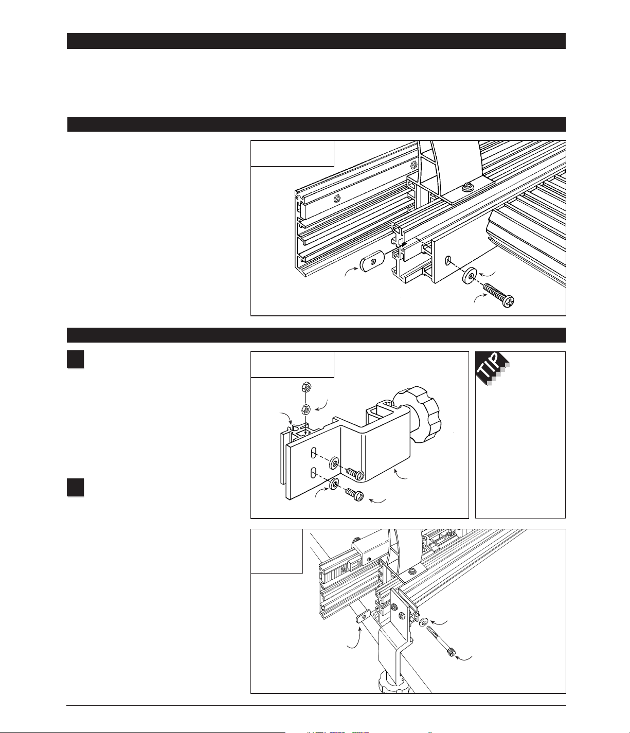
Assemble table clamps
With the table clamps on a flat surface,
insert the (2) #10-32 x
1
/2" phillips pan head
screws through the #10 flat washers then
through the holes in the clamp and loosely
attach the (2) #10-32 hex nuts. See Fig. 5.
Slide the hex nuts into the T-slot in the fence
mounting bracket and tighten the screws.
The ends of the fence mounting bracket
should be flush with the clamp edges.
Repeat for the other clamp.
Attach table clamps to
Intelli-Fence
Position the Intelli-Fence on your router table
with the opening in the fence centered on
your router’s collet.Inser t the
1
/4-20 x 2"
socket head cap screws through the
1
/4"
washers then through the fence mounting
bracket and loosely attach the
1
/4-20
rectangular nuts.Now slide the rectangular
nuts into the T-slots on the rear of the
Intelli-Fence.Tighten the clamping knobs to
secure the clamps to the table edge, then
tighten the two socket head cap screws using
the supplied hex key, Fig. 6.
FIG. 5
Assemble table clamps
3
FIG. 4
Attach to your INCRA Jig
MOUNTING TO YOUR ROUTER TABLE
Important: Your INCRA Jig Ultra or Pro must
be mounted to a
3
/4" plywood base and the
carriage clamp must be in the locked position
before installing the Intelli-Fence.
Insert the supplied #10-32 x 1" phillips pan
head screws through the
5
/8" o.d.(gold)
washers then through the holes on the back of
the INCRA Jig Ultra’s fence mounting bracket.
Loosely attach the (2) #10-32 rectangular nuts.
Now slide the rectangular nuts into the T-slot on
the rear of the Intelli-Fence. Position the fence
so that the INCRA Jig’s carriage is
approximately centered on the fence length
and tighten the two mounting screws.
Note: For mounting to the INCRA Jig Pro use
the shorter #10-32 x
1
/2" screws.
Your new INCRA Intelli-Fence can be used
either by clamping directly to your router
table or by attaching first to your INCRA Jig
Ultra or Pro.Mounting directly to your
INCRA Jig adds incremental positioning
1
Freestanding Mode
2
Note: The table clamps are designed to
work on router tables from 1
1
/8" to 13/8" thick.
To increase the thickness of a table less than
1
1
/8" thick, use double faced tape or glue to
attach a wooden strip to the underside of the
table edge.
#10-32 rectangular nut
#10-32 x 1" phillips pan head screw
5
/8" o.d. gold
washer
#10-32 hex nut
Fence
mounting
bracket
#10 flat washer
Table clamp
#10-32 x
1
/2" phillips
pan head screws
By loosening
the two phillips
head screws on
the table clamps
the fence angle
can be adjusted
perfectly square to
your router table.
FIG. 6
Attach table
clamps to
Intelli-Fence
1
/4" flat washer
1
/4 -20 x 2" socket head
cap screw
1
/4 -20 rectangular nut
Attaching to your INCRA Jig Ultra or Pro
control to the already substantial
features of your INCRA Intelli-Fence.
However, if you don’t already own an
INCRA Jig or you just prefer to use the
Intelli-Fence independent of your
INCRA Jig system, the supplied
clamps and instructions below will
allow you to quickly set up and
use the Intelli-Fence in the
freestanding mode.
Page 4
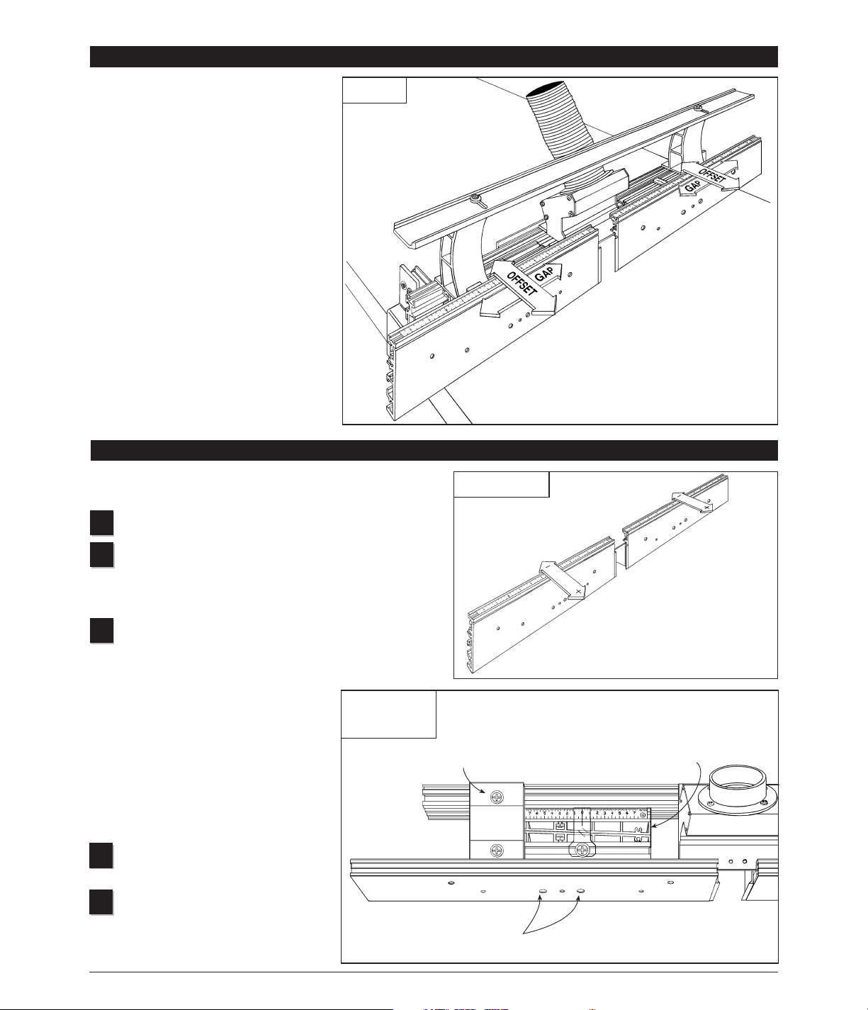
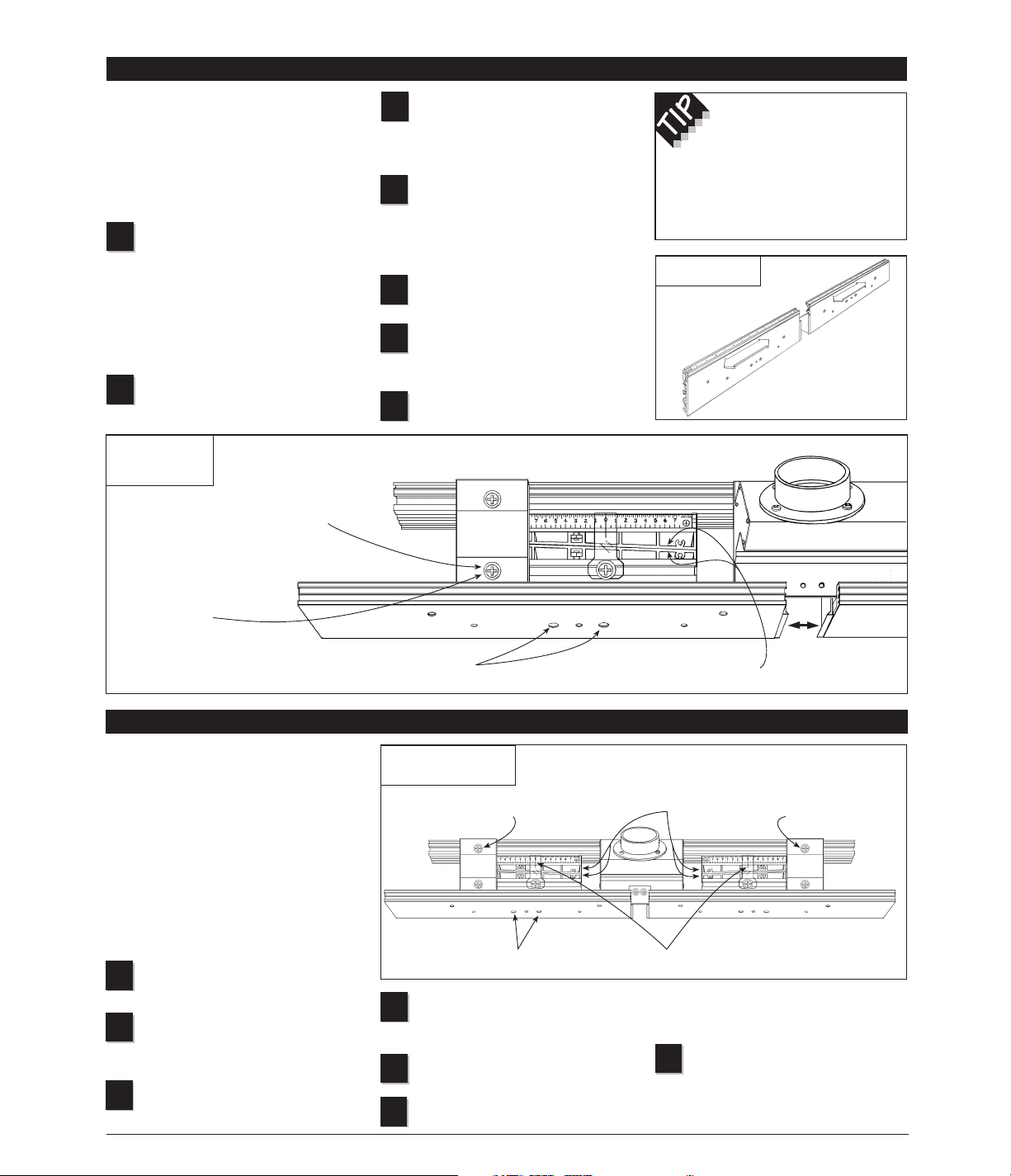
Follow these steps to adjust either the infeed or outfeed fence for
“in-line” or “offset” fence applications, see Fig 7:
Loosen the rear mounting screws on the Hi-Rise fence brace.
Using the supplied hex key, loosen the two socket head
screws through the large holes in the fence. Loosen each
screw one to two full turns, depending on the amount of
adjustment range needed.
Adjust the fence by sliding the rear wedge:
(+) to move the fence forward, slide the wedge
to the left to move the (+) end of the scale
toward the hairline cursor.
(-) To move the fence backward, slide the
wedge to the right to move the (-) end of the
scale toward the hairline cursor.
Note: The numbers on the scale represent
hundredths of an inch. Each of the smaller
tick marks on the top of the scale represent
.002" (two thousandths of an inch).
Tighten the two socket head screws
through the large holes in the fence.
Tighten the rear mounting screw on the
Hi-Rise fence brace.
First: Loosen rear
brace mounting screw
FIG. 7
Offset adjustment–
top view
4
Offset adjustment
Offset Adjustment
Offset Adjustment
5
4
OPERATION
1
2
3
Operation
The infeed and outfeed fences of the
Intelli-Fence can be moved independently
in two directions to provide a variety of
setup configurations. By making the
offset
adjustments
described below, you can
position the fences “in-line” for standard
routing operations such as grooving,
rabbeting, and joint making, or you can
“offset” the infeed and outfeed fences for
specialty cutting applications such as
shaping or jointing an edge. The
gap
adjustment
allows adjustment of the opening
between the infeed and outfeed fences from
5
/8" to 33/4". Follow the step by step
instructions below to familiarize yourself with
these two basic adjustments, then do the
initial fence and scale setup described on
page 5 and you’ll be ready to put your new
Intelli-Fence to work.
Caution: Always turn off the power and
make sure the router bit has come to a
complete stop before changing the setting
of any part of the Intelli-Fence.
Second: Loosen (2) socket head
screws through large holes in fence
Third: Slide rear wedge to
adjust fence offset
Fourth: Re-tighten (2) socket head screws
Note: Hi-Rise fence cap removed for clarity
Fifth: Re-tighten rear brace mounting screw
Page 5
Initial Fence and Scale Set Up
(In-line/mid-range position)
Initial Fence and Scale Setup (In-line/mid-range position)
Tighten the two socket head screws
through the large holes in both the
infeed and outfeed fence.
Tighten the rear mounting screws
on each of the Hi-Rise braces.
Test the in-line setup by sliding a
straight edged board down the
length of the fences. Fine-tune either the
infeed or outfeed fence as necessary.
Once the fences are located in line
with one another slide the infeed
and outfeed scales to read “0” under the
hairline cursors.
5
FIG. 9
In-line/mid-range position
In order to position the scales for
accurate readout, the infeed/outfeed
fences must first be positioned in-line
with one another with the adjustment
wedges at mid-range. Once the scales
are positioned you’ll easily be able to
return the infeed/outfeed fences to this
in-line/mid-range position for standard
in-line fence applications.You’ll also find
the in-line/mid-range position a good
starting point for any of the offset fence
applications. Here’s how, see Fig 9:
Loosen the rear mounting screws
on both Hi-Rise fence braces.
Loosen the two socket head screws
through the large holes in both the
infeed and outfeed fence.
Slide the rear wedge on each fence
to align the ends of the rear wedge
flush with the ends of the front wedge.
3
1
2
4
6
7
First: Loosen rear brace mounting screws
on both fence cap braces
Second: Loosen (2) socket head screws through
large holes in both infeed and outfeed fence
Third: Align ends of front
and rear wedges flush
Fifth: Tighten rear
mounting screws on
both fence cap braces
Sixth: Fine tune as necessary, then slide
scales to read “
0
” under hairline cursor
Fourth: Re-tighten all
(4) socket head screws
Note: Hi-Rise fence cap removed for clarity
5
Note the scale setting, then hold
the front and rear wedges together
as you slide the outfeed fence to open or
close the gap.
Make sure the scale setting is still
the same (slide the rear wedge to
adjust if necessary) then tighten the two
socket head screws through the large
holes in the fence.
Tighten the front screws on the
Hi-Rise fence brace.
Align and tighten the Hi-Rise fence
cap if it was moved to access the
fence brace screws (see Fig.1A, page 2).
Repeat Steps 1-6 for the infeed
fence.
4
5
6
7
Follow these steps to adjust the opening
between the infeed and outfeed fences,
see Fig. 8:
Caution: When adjusting the fence
opening, never position the fence ends
closer than
1
/8" from the router bit.
Loosen the front mounting screw on
the Hi-Rise fence brace. You can
either use a long shank phillips screw
driver to access the screw through the
slotted opening in the red fence cap or
simply loosen the fence cap retaining
screws and pivot the fence cap to provide
access to the front fence brace screw.
Using the supplied hex key, loosen the
two socket head cap screws through
the large holes in the outfeed fence.
3
1
2
Gap adjustments
FIG. 8
Gap adjustments–
top view
First: Loosen front brace
mounting screw
Second: Loosen (2) socket head screws
through large holes in fence
Fourth: Re-tighten (2)
socket head screws
Fifth: Tighten front brace
mounting screw
Note: Hi-Rise fence cap removed for clarity
To avoid accidentally
changing the fence offset, it
is usually best to begin in any
Intelli-Fence setup by making
the fence gap adjustment before
setting the fence offset.
Gap Adjustment
Third: Holding front and rear wedges
together, slide fence to open or close gap
Page 6
SAFETY
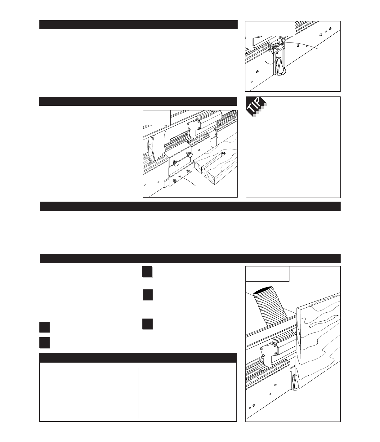
FIG. 12
Vertical panel raising
Adjust infeed/outfeed fences to the
in-line/mid-range position as
described on page 5.
Use a straight edge to adjust the
Hi-Rise fence cap in line with the
infeed and outfeed fences. (See Fig. 1A
on page 2.)
Remember: Do not make the full
width of the cut in a single pass.
Instead, use several light side-by-side
passes, moving the fence back
1
⁄16" or
so after each pass.
5
3
4
6
IN-LINE FENCE APPLICATIONS
Once set to the in-line/mid-range
position as described on page 5, your
new INCRA Intelli-Fence can be used
for a variety of typical in-line fence
applications, including grooving,
dadoing, and edge forming operations
such as rabbeting, chamfering, and
roundovers. You’ll also find the in-line
position useful for many specialty
operations. With the Hi-Rise fence cap,
you’ll be able to use vertical panel
raising bits to make raised panels for
cabinetry, and since its design is
compatible with all INCRA joint-making
accessories, you’ll be able to use the
Intelli-Fence in conjunction with
your INCRA Jig Ultra or Pro as a
joint-making fence.
Vertical Panel Raising
The introduction of the vertical panel
raising bit has made cutting the reveal on
a raised panel a relatively simple
operation for the router table. You’ll find
your new Intelli-Fence, with its built-in
dust collection, adjustable fence gap,
and Hi-Rise fence cap, perfect for this
operation.The setup is as follows, Fig 12:
Install vertical panel raising bit and
set appropriate depth of cut.
Adjust fence gap as necessary
(see Gap Adjustment on page 5).
1
2
❒
Whenever using large diameter
vertical or horizontal panel
raising bits or any other large
diameter bit, always follow
that router bit manufacturer’s
operation and safety
recommendations.
❒
Whenever it is necessary to
remove large amounts of
stock, always use multiple
side-by-side passes to achieve
the final cut. Several shallow
cuts are safer and will yield
better results.
FIG. 11
INCRA Stop
When used in conjunction with your new
INCRA Intelli-Fence, the INCRA Stop
provides the same precise rack positioning
capabilities that made the INCRA Jig
famous. The sliding scale in the top of the
fence becomes a versatile reference for use
in setting stop positions at the router table.
The adjustable plastic stop permits micro
adjusting of the stop positions anywhere
between the
1
⁄32" tooth spacing on the
INCRA racks. The bi-directional design
allows the INCRA Stop to function on the
infeed or outfeed end of the fence with any
thickness of stock.
INCRA STOP
INCRA Stop
INCRA Stop
The fence bridge can be
mounted with either the narrow
or wide end in the opening
between the infeed and outfeed
fences.With the narrow end forward
the fence opening will be 5⁄8".This
opening is great for smaller joint
making bits like the 1⁄4" and 3⁄8"
straight or the 1⁄4", 5⁄16", and 3⁄8"
dovetails. With the wider end of the
fence bridge forward the opening is
increased to 11⁄8", perfect for use
with larger dovetail bits.
FIG. 10
Fence bridge adjustment
The adjustable fence bridge is used during
joint making to provide support for narrow
vertically held stock as it is moved past the
opening between the infeed and outfeed
fences. For all other cutting operations the
fence bridge can be positioned behind the
front face of the Intelli-Fence and tightened
in place. For use during joint making, first
return the fences to the in-line/mid-range
position described above. Loosen the
screws that secure the fence bridge and
slide it forward into the opening between
the fences. Adjust the fence gap as
described on page 5 to close the fence
ends on the bridge. Now use a straight
edge to locate the fence bridge flush with
the front face of the fence and tighten the
mounting screws.See Fig 10.
Fence Bridge Adjustment
Loosen
mounting screws
and slide fence
bridge forward for joint
making applications
Use straight edge to align fence
bridge flush with fences
Fence
bridge
Page 7
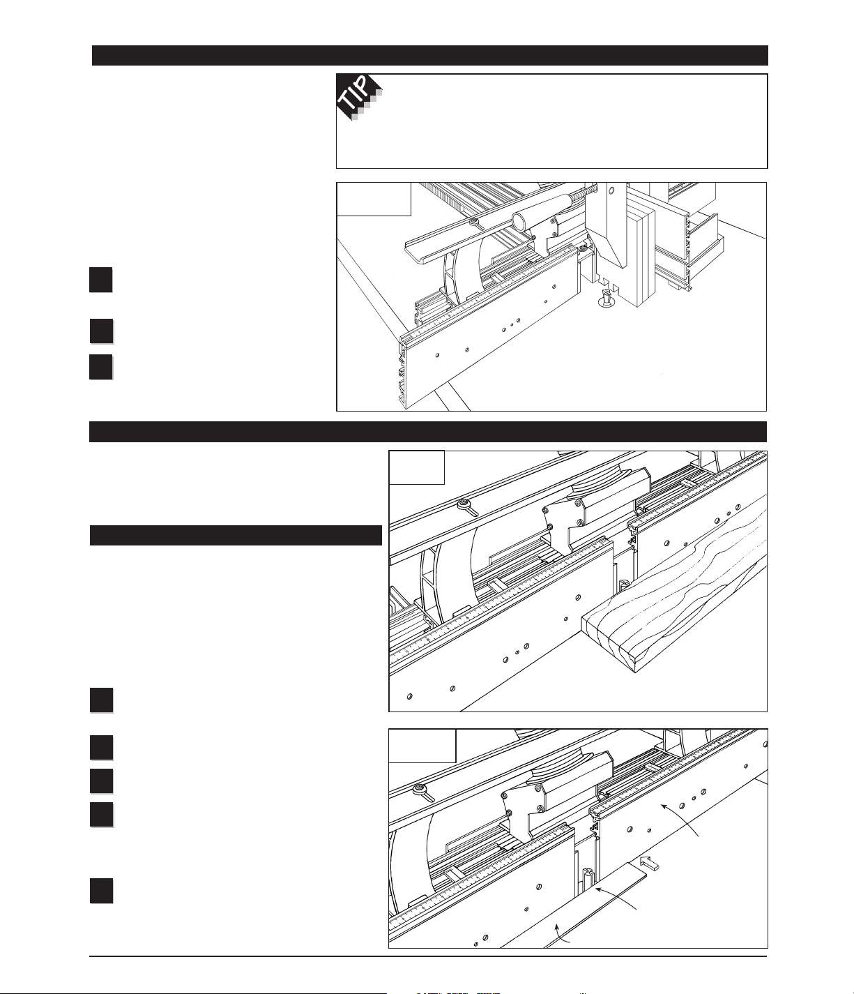
Jointing
Most woodworking projects require that your boards begin
with at least one straight edge. This one straight edge then
becomes the reference surface for subsequent
perpendicular or parallel cuts. By using your Intelli-Fence
and the technique described below, you’ll be able to put a
perfectly straight edge on your board at the router table
and, because of the higher RPM of the router, you’ll find
the freshly jointed edge far smoother than any jointer
machine can produce.
Install a
1
/2" diameter (or larger) straight bit and set
the depth of cut to slightly greater than the thickness
of stock to be joined.
Adjust fence gap as necessary (see Gap Adjustment
on page 5).
Adjust infeed/outfeed fences to the in-line/mid-range
position as described on page 5.
Adjust the location of the Intelli-Fence at your router
table to place the outfeed fence in line with the
outermost cutting arc of the router bit. (A straight edge
placed against the outfeed fence can be used to help
align the fence with the cutter.) Fig.15.
Micro adjust the infeed fence backward (-). The
reading on the scale will represent the amount of
stock you wish to remove from the board’s edge on each
pass. A light cut (infeed cursor reading between -1 and -2)
will yield the smoothest results.
Adding an INCRA Jig Ultra or Pro to your
Intelli-Fence makes precise placement of
multiple side-by-side cuts a cinch. One such
operation requiring this kind of precision is
joint making. Once placed in the
in-line/mid-range position, your new
Intelli-Fence becomes a perfect replacement
for the standard straight fence commonly
used with the INCRA Jig. It is completely
compatible with all of the INCRA jointmaking accessories, including the INCRA
Right Angle Fixture, Stop, and joinery
templates. The setup follows, see Fig 13:
Adjust infeed/outfeed fences to the
in-line/mid-range position as described
on page 5.
Position fence bridge and adjust fence
gap as described on page 6.
Follow the instructions for the joint you
wish to cut as detailed in the INCRA
Master Reference Guide and Template
Library.
One of the most valuable features of the Intelli-Fence is
the ability to offset the infeed and outfeed fences. The
offset fence adds a whole new dimension to the router
table, allowing it to perform two new operations—
jointing, and shaping.
2
FIG. 14
Jointing
7
OFFSET FENCE APPLICATIONS
1
FIG. 15
Jointing setup
First: Position Intelli-Fence to
align fence with cutting wing
on the router bit
Second: Micro
adjust infeed fence
backward (-)
Straight edge
3
4
5
3
1
2
FIG. 13
Joint Making
Joint Making (INCRA Jig Ultra or Pro required)
Clearance is provided for between the Hi-Rise fence cap, the braces and
all INCRA joint-making accessories. However, since the Hi-Rise fence cap and
braces are not necessary for joinery, you may remove them from the Intelli-Fence
if you prefer. Just reverse the assembly instr uctions descr ibed on page 2.
Outfeed fence
Infeed fence
Page 8
For a product information brochure, call, write or fax to:
Taylor Design Group, Inc.
P.O. Box 810262, Dallas, TX 75381
Tel: (972) 418-4811 Fax: (972) 243-4277
Web Site: www.incra.com
PRODUCT INFORMATION
8
Made in America by:
Taylor Design Group, Inc.
■
P.O.Box 810262 ■Dallas, Texas 75381 1195
Printed in the U.S.A. © 1995, Taylor Design Group, Inc. INCRA is a registered trademark of Taylor Design Group, Inc.
WARRANTY
Taylor Design Group, Inc.warrants this product for one year from date of purchase.We will repair
any defects due to faulty mater ial or workmanship, or at our option, replace the product free of
charge. Please return the failing component only, postage prepaid, along with a description of the
problem to the address below. This warranty does not apply to parts which have been subjected to
improper use, alteration, or abuse.
LIFETIME WARRANTY ON POSITIONING RACKS
If an INCRA positioning rack in this tool becomes damaged for ANY reason, Taylor Design Group
will replace it free of charge for as long as you own your tool. Return the damaged rack, postage
prepaid, and allow 1 to 2 weeks for deliver y.
NOTE:
Replacements cannot be sent unless damaged racks have been received by Taylor Design Group.
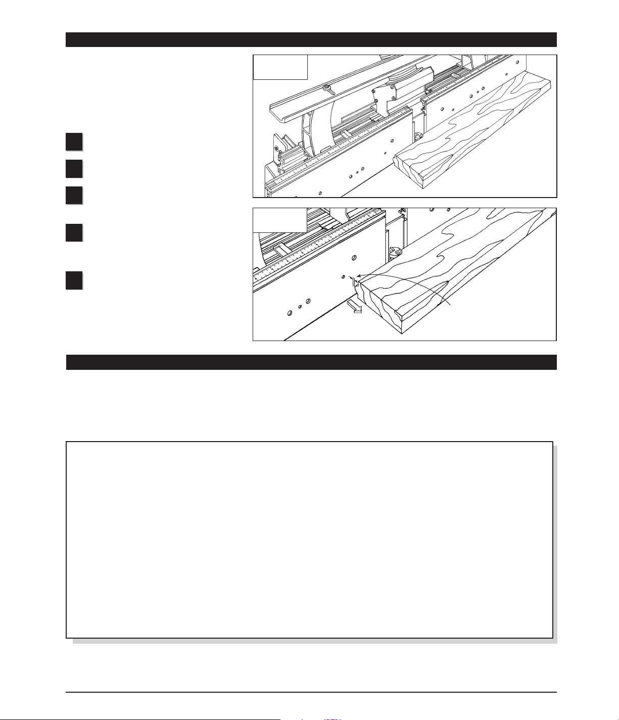
FIG. 16
Shaping
FIG. 17
Shaping setup
Distance between stock and
outfeed fence – micro adjust
outfeed fence forward by this
amount
Outfeed fence
Infeed fence
Many shaping operations involve the removal of
the entire edge of a square piece of stock as it is
moved past the cutter. Once the stock is
removed from the edge, it becomes necessary to
support the freshly cut surface by moving the
outfeed fence forward. Although similar to
jointing, the setup is slightly different. Here’s how:
Install router bit and set desired depth of
cut.
Adjust fence gap as necessary (see Gap
Adjustment on page 5).
Adjust infeed/outfeed fences to the
in-line/mid-range position as described on
page 5.
Adjust the location of the Intelli-Fence at
your router table to achieve the desired cut
profile. Use a scrap piece of wood and make trial
cuts to help in determining the fence position.
Make a fresh test cut about 3" long on a
piece of scrap stock, then turn off the
router. You’ll notice a gap between the freshly
cut surface and the outfeed fence, Fig. 17.
Simply micro adjust the outfeed fence forward by
this amount to support the stock’s edge as it
passes the cutter.
2
5
3
4
1
Shaping
For a product information update on the complete
INCRA line of tools, please see your nearest dealer.
If you are unable to locate a store nearby, or if you
have trouble finding a particular product, we will
honor your order directly.
 Loading...