

Page 1

®
Modular
Jig & Fixture
it
System
Works wit h all INC RA Track & INCRA T-Trac k Compone nts and Accessori es
Platform System
Build-It
Components
• Large Build-It Panel
• Small Build-It Panel
• T-Slot Panel Connector
• 18” or 24” Miter Slider
• INCRA Build-It Clamp
• INCRA Build-It Bracket
• INCRA Build-It Knobs
• INCRA T-Track
• INCRA T-Track PLUS
• INCRA Track (not shown)
• INCRA Shop Stop
(not shown)
Sliding Cutoff Table Showing Major Components & Features of the System
Large Build-It Panel
INCRA Build-It Clamp
Build-It Bracket
(Includes all fasteners)
Miter Slider
Adjustable-width
aluminum runner
T-Slot Panel Connector
Interconnects Build-It Panels
(accepts 1/4” bolts and nuts)
Large Build-It Panel
INCRA T-Track Plus
INCRA T-Track
Wooden Fence
Pre -cut hol es and rabbet
to atta ch T-Slot Panel
Con nect ors on both sides
of Buil d-It Panels
Small Build-It Panel
Multiple rows of pre-drilled
holes for mounting INCRA
Miter Slider wherever needed
Build-It Knob
Counterbored holes on front and
back edges for mounting user
made fences and other accessories
The INCRA “Build-It“ Modular Jig & Fixture Platform System
The INCRA Build-It Modular Jig & Fixture Platform System is a highly versatile NEW method for quickly and easily creating an extremely wide
variety of common and special purpose jigs, fixtures and those one-of-a-kind work helpers that you typically find hanging on the walls and
rafters in just about any woodshop.
The Build-It System begins with INCRA’s Miter Slider adjustable aluminum runners. With hundreds of thousands of units already in circulation, these
tried and true jig and fixture runners have become a workshop staple for the production of sliding and fixed base jigs.
But it’s the NEW INCRA Build-It Panels and T-Slot Panel Connectors that put the punch in this system. The Build-It Panels are pre-cut and
pre-drilled to instantly accept all of the components of the system. You can add a Miter Slider in seconds and it’s automatically square to
your saw blade with no tedious measuring or drilling required, then mount a fence in moments using the counterbored mounting holes. The
glue that holds everything together is INCRA’s innovative NEW T-Slot Panel Connector. These specially designed aluminum components
serve to simultaneously interconnect the panels and provide a rock solid T-Slot for adding and holding jig accessories, fences, stops and
Build-It Clamps. With INCRA’s NEW Build-It Modular Jig & Fixture Platform System you just connect the parts with a screwdriver and the included
fasteners. The possibilities are endle ss!
Page 2

®
it
System
The INCRA Build-It assembly shown in the instructions that follow was chosen to illustrate a configuration using
all of the main components of the system and requiring each of the few simple assembly and trimming operations that are likely
to be encountered when putting the components together. Just remember that the example shown is by no means the only
configuration possible. By using different combinations of the Build-It Panels, T-Slot Panel Connectors and Miter Sliders,
hundreds of highly useful configurations are possible - like those shown on the opposite side of this instruction card. And
that’s just the beginning!
Also, keep in mind that while the table saw chosen to illustrate these instructions is an important candidate for sliding jigs
and fixtures, there are many other stations in the shop that will benefit from the increased safety, accuracy and repeatability
afforded by shop-made jigs. The NEW INCRA Miter Slider owner’s manual includes specific plans for some useful common and
specialty jigs that take advantage of the unique features of the Built-It System’s components. Don’t forget to check out the variety
of great books already available on the subject of beneficial jigs and fixtures for your workshop. Now let’s get started...
Left or Right Miter Slot?
While many tools in your shop like the band saw, router table or sanding
station have only one miter channel, the table saw has two, and often a
choice must be made to determine on which side of the blade the “business”
side of your jig will slide. In choosing, just remember that for any cut requiring
a tilted saw blade, you’ll want the blade to tilt safely away from the main
components of your jig, and most importantly, away from your hands. All of
the instructions to follow will illustrate only a left side of blade assembly.
1. Adjust Miter Slider and Attach Build-It Panel
Begin by adjusting an INCRA Miter slider at each of the expansion
mechanism locations for a good sliding fit in your table saw’s miter slot.
Now attach a small Build-It Panel to the Miter Slider as shown in Fig. 1 using
the (4) 10-24 x 3/4” flat head Phillips screws supplied with the Miter Slider.
2. Attach Panel Connectors
Using the supplied 10-24 x 1/2” flat head Phillips screws, attach a panel
connector to each side of the small Build-It panel, Fig. 2. CAUTION: Make
sure that no part of the aluminum Panel Connector overlaps the
projected line of cut!
This simple assembly can be used for a variety of jigs. The T-slots on the
twin Panel Connectors provide an easy and secure means of attaching
the components of your jig’s design to the sliding Build-It platform using
standard 1/4-20 hex bolts. Just take a look at the tenoning & raised
panel cutting fixture in Fig. 3, then let’s keep building.
Fig. 2 Attach Panel Connectors
10-24x1/2” Phillips screw
Left Side
Fig. 1 Attach Build-It Panel to the Miter Slider
10-24x3/4” Phillips screw
Small Build-It Panel
Miter Slider
Fig. 3 Tenoning Jig Using Basic Build-it Assembly
Specific plans for this jig can
be found in the new Miter
Slider owner’s manual
Right Side
Panel Connectors
Line of Cut
Page 3

®
it
System
3. Extend Build-It Panel to Blade
While the T-Slot Panel Connectors are a useful and important commod-
ity in attaching user made jig components, fences, stops and Build-It
Clamps, they also provide an easy means of adding additional Build-It
Panels to expand the size of your jig design. For example, you might
want to extend support for your jig design to the blade. A large Build-It
Panel is often a good choice here. Just attach the panel as shown in Fig.
4 with the supplied 10-24x1/2” f lat head Phillips screws. You’ll want
the area on the panel with the largest concentration of mounting
holes positioned away from the small panel. Now we’ll trim the panel
to your saw blade.
Fig. 4 Extend Build-It Panel to Blade
10-24x1/2” Phillips screw
Large Build-It Panel
4. Trim Build-It Panel to Blade
BLADE ANGLE NOTE: If the primary use for your jig’s design will be to make 90 deg. vertical cuts, be sure that the blade is set to 90 deg. before continuing.
Raise your blade about 3/4” and make a cut by sliding the Build-It assembly to remove the portion of the large Build-It Panel that extends across the line
of cut, Fig 5. Reserve the cutoff for later use as described in Step 6.
With a Build-It Panel extending all the way to the blade, your Build-It assembly can now be used to support a workpiece for crosscut operations like the
simple “shooter board” jig shown in Fig. 6. Now let’s add some size to our panel configuration for use with larger workpieces.
Fig. 5 Trim Build-It Panel to Blade
Build-It assembly
Fig. 6 “Shooter Board“ Jig
Large Build-It
Panel after cut
5. Increase Build-It Assembly Size
You can now add additional Build-It Panels and T-Slot Panel Connectors
as required to create a support platform to fit the size and scope of your
project needs. In Fig 7, we’ve added a large Build-It Panel to the left
edge of our assembly to increase workpiece support. Now, let’s take
a look at how you can use the cutoff reserved from Step 4 to extend
workpiece support beyond the blade.
Fig. 7 Increase Build-It Assembly Size
10-24x1/2” Phillips screw
Add Large Build-It Panel
6. Extend Build-It Panel Beyond the Blade
Some jig designs may benefit from workpiece or cutoff support on the
opposite side of the blade. A simple “drop panel” locked in place adjacent to the blade provides zero clearance and workpiece cutoff support.
Here’s how to add one to the Build-It assembly we’ve been working on.
Lower the blade and remove your Build-It assembly from the left hand
miter slot. Drop an INCRA Miter Slider into the right hand miter slot and
adjust for a good sliding fit. Using the row of mounting holes that allows
the least amount of overhang beyond the line of cut, attach the cutoff
reserved from Step 4 to the Miter Slider with the (4) supplied 10-24 x 3/4”
flat head Phillips screws. The rabbeted edge on the Build-It Panel should
be oriented away from the blade as shown in Fig. 8.
Fig. 8 Add “Drop Panel“ to Opposite Side of Blade
Cutoff reserved from Step 4
10-24x3/4” Phillips screw
Rabbeted edge of panel
Miter Slider
Page 4
®
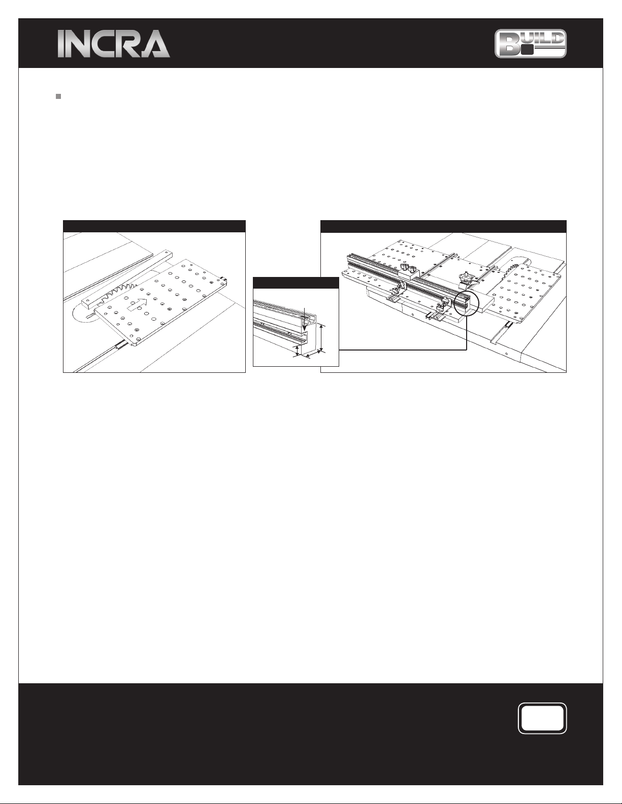
7. Trim Build-It Panel to Blade
Raise the saw blade about 3/4” and make a cut to trim off the portion
of the panel that extends beyond the line of cut, Fig. 9. Now, when
you return the left hand Build-It assembly to the table saw, the right
hand “drop panel” can be positioned adjacent to the blade and locked
in place by tightening the two Miter Slider expansion mechanisms to
provide workpiece cutoff support.
it
System
Fig. 10 shows the completed Build-It assemblies put together to create
a very useful sliding cutoff sled. The wooden fence shown includes the
addition of INCRA’s T-Track and T-Track Plus, see Fig. 11 for dimensions.
The fence is held in place with a pair of Build-It Brackets and the knobs
included with the brackets. This arrangement allows the fence to be
positioned at any location and at any angle on top of the sled. The
workpiece is positioned with a user made wooden stop and is securely
held in place with the INCRA Build-It Clamp.
Fig. 9 Trim Build-It Panel to Blade
Fig. 11 T-Track Fence
3/4” wide x 1/2”
deep groove
5
/8”
11/4”
Fig. 10 Sliding Cutoff Sled
13/4”
Manufactured by:
Taylor Design Group, Inc.
P.O. BOX 810262 Dallas, TX 75381
ww w.in cra.com
INCRA is a Registered Trademark of Taylor Design Group
©2007 Taylor Desig n Group, Inc.
MADE IN THE
USA
INCR A Tools are protect ed by one or m ore of the f ollowing US pat ents:
#4, 793,6 04, #4,930, 221, #5,195,730, #5 ,275,0 74, #5, 423, 360, #5,716,0 45, #6 ,237,4 57, #6,55 7,6 01, #6,67 2,190.
Oth er pat ents granted or p endin g.
 Loading...