

Page 1
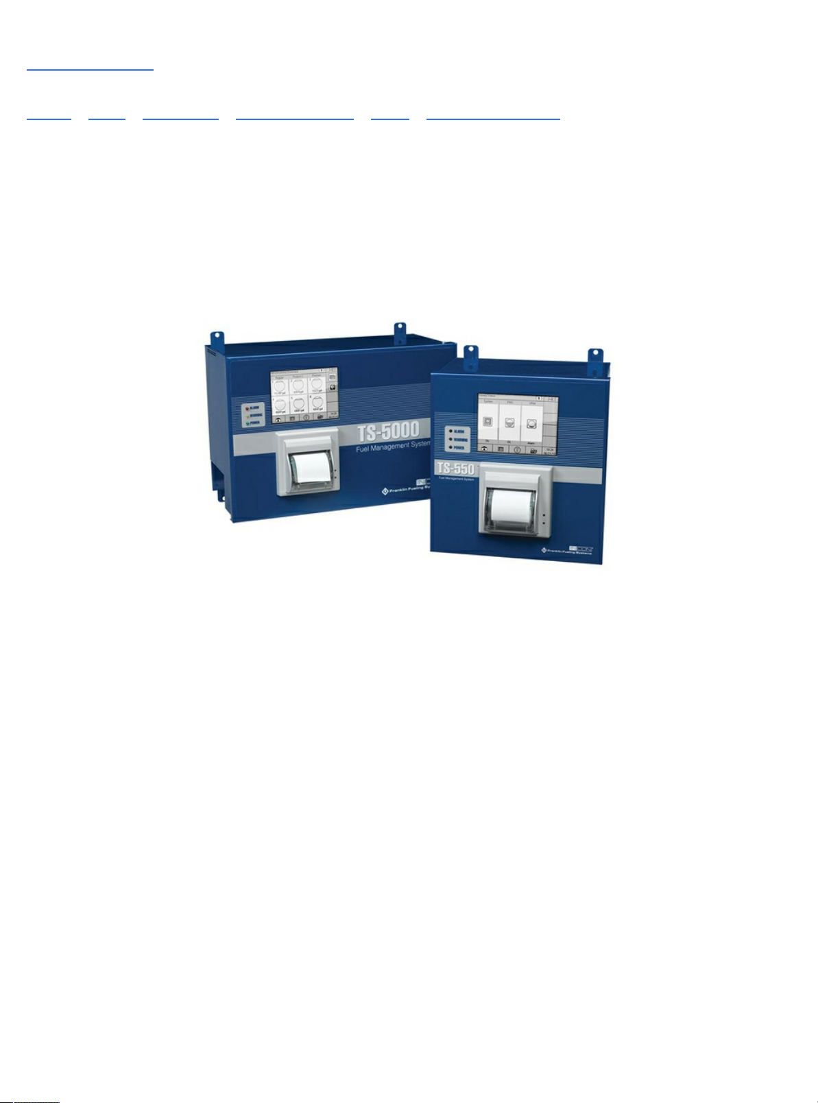
Manuals / Brands / Incon Manuals / Measuring Instruments / TS-550 / Installation & user manual / PDF
INCON TS-550 INSTALLATION & USER MANUAL
Quick Links
Available Configurations
Scm Setup (Console Programming)
Ac Input Module
Alarms
Scm Alarms and Warnings
Clearing Alarms
Page 2

Table of Contents
Table of Contents
Applications
Site Requirements
Available Configurations
AC Input Module
4-20mA Input Module
Relay Module
Turbine Pump Interface (TPI) Applications (Alternate STP Control)
Secondary Containment Monitoring Application
SCM Status Summary Screen
SCM Control Screen
Status Indicator Table
Control Indicator Table
Learn Indicator Table
Required Equipment
Containment Tightness and Continuity Test
STP Siphon Flow Rate Test
When to Learn/Re-Learn
Procedure
Learn Messages
SCM Alarm Reports
Application Event Reports
SCM Alarms and Warnings
Clearing Alarms
Enabling SCM Channels
Disabling SCM Channels
Page 3
Secondary Containment Monitoring
Installation & User’s Guide
TS-550/TS-5000 consoles
Franklin Fueling Systems • 3760 Marsh Rd. • Madison, WI 53718 USA
Tel: +1 608 838 8786 • 800 225 9787 • Fax: +1 608 838 6433 • www.franklinfueling.com
Page 4

Notice
Franklin Fueling Systems (FFS) strives to produce the nest manual possible and to ensure that the information that
it contains is complete and accurate. However, FFS reserves the rights to change this document and specications at
any time without notice. FFS makes no expressed or implied warranty with regard to the contents of this manual. FFS
assumes no liability for errors, omissions or for any damages, direct or consequential, that may result from the use of this
document or the equipment that it describes.
This manual is for use expressly with the TS-550, TS-5000, and TS-SCM at their approved specications.
For further information and installation and programming instructions, please refer to the T5 Series Installation Guide (p/n
000-2150) and/or T5 Series Programming Guide (p/n 000-2142).
Trademarks
INCON®, Tank Sentinel®, System Sentinel®, System Sentinel AnyWare® and Tank Sentinel AnyWare® are registered
trademarks of Intelligent Controls. All brand and product names are trademarks or registered trademarks of their
respective companies.
Inspection of Materials
Visually inspect all components for defects or damage prior to installation. If any defect or damage is found, do not use the
product and contact Franklin Fueling Systems for further assistance.
Warranty Information
Please refer to the FFS Fuel Management Systems & Product Warranty Policy for all warranty information.
Contacting Franklin Fueling Systems (FFS)
Please feel free to contact us by mail at:
Franklin Fueling Systems
3760 Marsh Rd.
Madison, WI 53718 USA
Or contact us by phone, fax or e-mail:
Ofce and Sales Hours: 8 a.m. to 5 p.m. CST - Monday through Friday
Technical Support Hours: 7 a.m. to 7 p.m. CST - Monday through Friday
Please visit our website at www.franklinfueling.com
Copyright ©2007 by Franklin Fueling Systems (FFS). No part of this publication may be reproduced in any form without the prior written consent of FFS.
ii
All rights reserved.
Page 5

Contents
Notice..................................................................................................................................ii
Important Safety Messages .............................................................................................. 1
Overview.............................................................................................................................2
Applications ..............................................................................................................................2
Site Requirements .................................................................................................................... 3
Available Congurations .................................................................................................................. 3
Installation ..........................................................................................................................4
SCM Setup (Console Programming) ................................................................................7
AC Input Module .......................................................................................................................7
4-20mA Input Module ................................................................................................................8
Relay Module ............................................................................................................................ 8
Turbine Pump Interface (TPI) Applications (Alternate STP Control) ......................................... 10
Secondary Containment Monitoring Application ....................................................................... 11
SCM Status and Control Screens ....................................................................................12
SCM Status Summary Screen .................................................................................................. 12
SCM Control Screen ................................................................................................................. 13
Status Indicator Table ...................................................................................................................... 13
Control Indicator Table .................................................................................................................... 13
Learn Indicator Table ....................................................................................................................... 13
Pre-Operational Containment Testing ............................................................................. 14
Required Equipment .................................................................................................................14
Containment Tightness and Continuity Test .............................................................................. 14
STP Siphon Flow Rate Test ...................................................................................................... 16
Learn Process .................................................................................................................... 17
When to Learn/Re-Learn .......................................................................................................... 17
Procedure ................................................................................................................................. 17
Learn Messages ....................................................................................................................... 18
SCM Reports ...................................................................................................................... 19
SCM Alarm Reports .................................................................................................................. 19
Application Event Reports ........................................................................................................19
Alarms ................................................................................................................................20
SCM Alarms and Warnings ....................................................................................................... 20
Clearing Alarms ........................................................................................................................21
Enabling/Disabling SCM ...................................................................................................22
Enabling SCM Channels ........................................................................................................... 22
Disabling SCM Channels .......................................................................................................... 22
SCM Annual Functional Testing ....................................................................................... 23
iii
Page 6
Important Safety Messages
INCON equipment is designed to be installed in association with volatile hydrocarbon liquids such as gasoline and diesel
fuel. Installing or working on this equipment means working in an environment in which these highly ammable liquids
may be present. Working in such a hazardous environment presents a risk of severe injury or death if these instructions
and standard industry practices are not followed. Read and follow all instructions thoroughly before installing or working
on this, or any other related, equipment.
As you read this guide, please be aware of the following symbols and their meanings:
Warning
Caution
Danger
Warning
Warning
This symbol identies a warning. A warning sign will appear in the text of this document when a potentially
hazardous situation may arise if the instructions that follow are not adhered to closely. A potentially hazardous
situation may involve the possibility of severe bodily harm or even death.
This is a caution symbol. A caution sign will appear in the text of this document when a potentially hazardous
environmental situation may arise if the instructions that follow are not adhered to closely. A potentially
hazardous environmental situation may involve the leakage of fuel from equipment that could severely harm
the environment.
This symbol identies an electrical danger. An electrical danger sign will appear in the text of this document
when a potentially hazardous situation involving large amounts of electricity may arise if the instructions that
follow are not adhered to closely. A potentially hazardous situation may involve the possibility of electrocution,
severe bodily harm, or even death.
Follow all applicable codes governing the installation and servicing of this product and the
entire system. Always lock out and tag electrical circuit breakers while installing or servicing
this equipment and any related equipment. A potentially lethal electrical shock hazard and the
possibility of an explosion or re from a spark can result if the electrical circuit breakers are
accidentally turned on during installation or servicing. Please refer to the Installation and Owner’s
Manual for this equipment, and the appropriate documentation for any other related equipment, for
complete installation and safety information.
Follow all federal, state and local laws governing the installation of this product and its associated
systems. When no other regulations apply, follow NFPA codes 30, 30A and 70 from the National Fire
Protection Association. Failure to follow these codes could result in severe injury, death, serious
property damage and/or environmental contamination.
Warning
Warning
Warning
Warning
Warning
Warning
Always secure the work area from moving vehicles. The equipment in this manual is usually
mounted underground, so reduced visibility puts service personnel working on this equipment in
danger from moving vehicles entering the work area. To help eliminate these unsafe conditions,
secure the area by using a service truck to block access to the work environment, or by using any
other reasonable means available to ensure the safety of service personnel.
When the Tank Sentinel system is used to monitor tanks containing gasoline or other ammable
substances, you may create an explosion hazard if you do not follow the requirements in this
manual carefully.
All wiring must enter the console’s enclosure through the designated knockouts. An explosion
hazard may result if other openings are used.
All wiring from probes or sensors to the Tank Sentinel console must be run in conduit separate
from all other wiring. Failure to do so will create an explosion hazard.
Substituting components could impair intrinsic safety. T5 series consoles are intrinsically safe
for sensors installed in – Class I, Division 1, Group D – hazardous locations. Substitution of
components could make the energy limiting circuitry in the system ineffective and could cause
an explosion hazard. Repairs to a T5 series console or attached components should only be
performed by a qualied, factory-trained technician.
TS-SCCM contains aluminum, care must be taken to avoid ignition due to impact.
1
Page 7
Overview
The TS-SCM (Secondary Containment Monitoring) system is a continuous secondary containment monitoring system that
monitors the interstitial spaces of double walled tanks and sumps, secondarily contained product and vapor return piping.
This product can be ordered as an available option with Franklin Fueling Systems’s TS-550 and TS-5000 FMS consoles.
The TS-SCM system is comprised of an application running on a T5 series FMS console and all necessary input and
output modules with installation kits. The Secondary Containment Control Module (SCCM) consists of a vacuum sensor,
solenoid valve, mechanical bypass valve, and vacuum manifold. SCM uses the STP siphon port vacuum to evacuate the
containment space and AutoLearn® technology to determine the characteristics of each secondary containment area that
is monitored.
Warning
SCM equipment operates at a standard 2" to 6" Hg and should only be used to monitor containments that are designed to withstand these vacuum levels. Refer to the containment manufacturer
for further information.
Applications
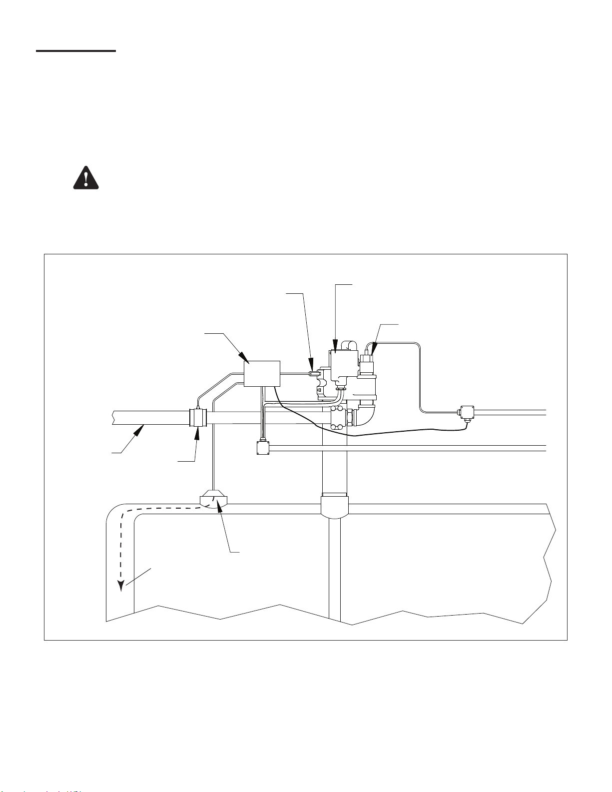
The following diagram illustrates a typical installation of SCM equipment inside of a STP sump.
FE Petro
Submersible
Pump
TS-LSU500
High Voltage Conduit
APT
Double Wall
Product Pipe
Syphon
Check Valve
Integral Solenoid
Vacuum Sensor
TS-SCCM/1
APT
Test
Boot
Intrinsically
Safe Conduit
To Bottom
of Tank
Tank
Containment
Install Kit
Figure 1 – TS-SCM System Overview
2
Page 8
Site Requirements
Total Containment Volume*
Normal Operating Vacuum 2" – 6" Hg (1 – 3 PSIG)
Pre-Programmed Maximum
Shutdown (Alarm Condition)
Mechanical Relief Valve
Vacuum**
Jumper Tubing Use only supplied vacuum tubing
Vacuum Sensor Wiring
Solenoid Wiring
Minimum - 0.25 gallons (1 L)
Maximum - 500 gallons (1879 L)
9" Hg (4.5 PSIG)
10" Hg (5 PSIG)
Belden No. 87761(0.12" OD) to 400 ft.
Belden No. 89182(0.31" OD) to 500 ft. (maximum distance)
600 V, 18 AWG minimum, UL approved
refer to ANSI/NFPA70 or CEC electrical codes
*Refer to manufacturers’ installation
guides or data sheets to calculate
containment area volumes.
**All containment areas MUST be
compatible with the vacuum levels
listed.
Note: SCM should be tested annually after installation.
The term containment (in secondary containment) refers to the interstitial spaces of double walled piping, sumps and
tanks that serve as a secondary containment if the primary containment is damaged.
Individual containment sections of a given product pipeline may be jumpered together via a vacuum line to form one larger
single containment. An example of ‘jumpered’ containment spaces is the secondary containment layer of product piping
from the turbine containment to the rst dispenser, and then jumpered to the secondary containment layer of the same
product piping on the other side leading to the next dispenser containment area.
Several containment areas may be grouped together and used with a single Secondary Containment Control Module (TSSCCM). No more than four (4) SCM groups should be used per pump siphon. The combination of any containment group
may not exceed the volume limits listed for SCM.
Note: DO NOT jumper tank interstitials with other tank interstitials or other containments.
Note: DO NOT jumper containment areas of unlike product pipelines together.
Note: If grouping multiple containment areas together, the installer will need to purchase and use the vacuum hose,
ttings, and clamps to secure the connection as specied by FFS.
Note: Both intrinsically safe and explosion proof conduits need to be available inside of the turbine containment for the
TS-SCCM.
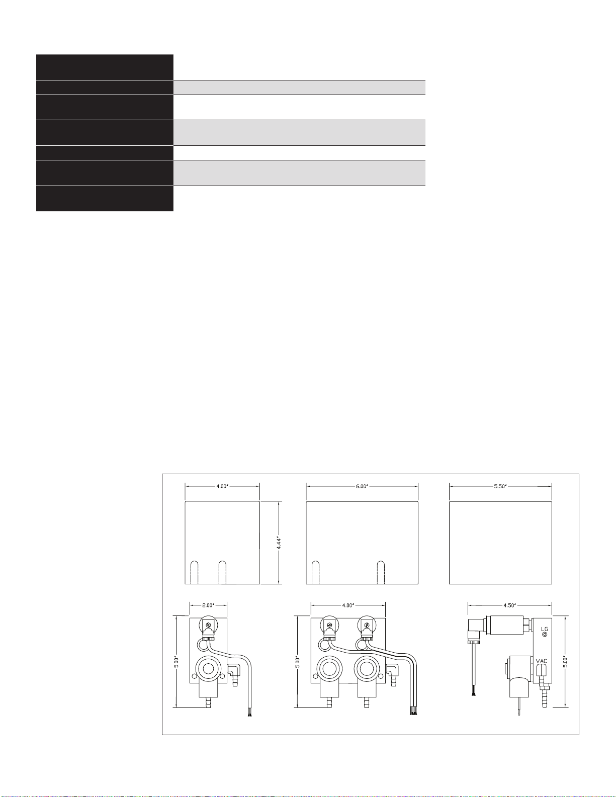
Available Congurations
Refer to Franklin Fueling
Systems’s current Fuel
Management Systems
Product Catalog for
a complete listing
of the current SCM
congurations offered.
Note: The SCCM 1 (as
pictured in Figure
2) can monitor one
containment group
and the SCCM
2 can monitor
two containment
groups.
TS-SCCM/1 TS-SCCM/2 TS-SCCM Side View
Figure 2 – SCCM 1 and SCCM 2 Dimensions
3
Page 9
Installation
Before starting installation, conduct a site survey to identify potential containment groups. Based on that survey, plan out
which STP sump the equipment will be installed in and how containment areas will be grouped together.
Warning
Lockout and tag circuit breakers, and disconnect console power wiring before installing or servicing
any system wiring.
Warning
Warning
Caution
DO NOT make solenoid and/or sensor wiring connections with live power connected to the console
or any module.
TS-SCCM contains aluminum, care must be taken to avoid ignition due to impact.
Do not run intrinsically safe (IS) wiring and non-intrinsically safe (non-IS) wiring in the same
conduit.
Note: TS-SCCM must be installed in accordance with the national electrical code, ANSI/NFPA 70, CEC or other
applicable national or local codes.
Note: Maximum torque on supplied hose clamps is 20 inch-lbs.
1. Pull all wiring through the conduits that will be used for the TS-SCCM vacuum sensor and solenoid valve. The
intrinsically safe (IS) sensor wiring must be run in an IS conduit. The non-IS solenoid wiring must be run in an
approved explosion proof rigid metal conduit.
2. Mount the TS-SCCM inside of the turbine
containment area, supported by rigid,
explosion proof conduit. Then orientate the
units to allow enough clearance to make the
vacuum line connections without stretching,
kinking, or creating sharp bends in vacuum
hoses. The SCCM cover is installed with the
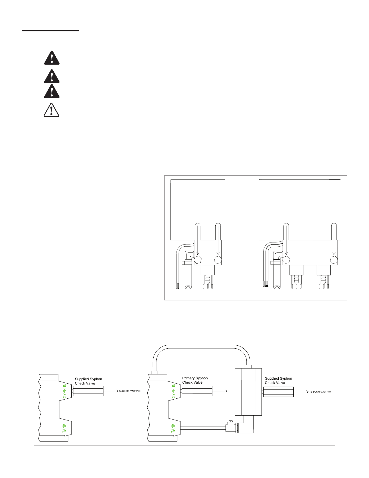
label upwards. See Figure 3.
3.
Connect the solenoid wiring to the eld wiring
using wire nuts to secure the connections.
Replace the explosion proof junction box cover.
4. Connect the vacuum sensor wiring to the IS
eld wiring using epoxy wire seals to secure
the connections. Replace the IS junction box
cover.
5. Install the supplied Siphon Check Valve with
the inscribed Flow Arrow pointing to the STP.
Apply a non-hardening, thread sealing
TS-SCCM/1 TS-SCCM/2
Figure 3 – Cover Installation (rear view)
compound to the threads, then thread the valve body into the submersible turbine’s siphon port. If necessary, use a
FFS Secondary Syphon Assembly to connect the SCCM to the syphon port of the STP.
Single Syphon (typical)
Secondary Syphon
Assembly
STPSTP
Secondary Syphon Kit
Figure 4 – Secondary Syphon Assembly Installation
4
Page 10
6. Plumb the siphon hose from the VAC port of the TS-SCCM to the siphon check valve. Secure the hose to the ttings
Earth Ground
using one of the supplied hose clamps at each end.
7. Plumb the containment vacuum hose from the INT port of the TS-SCCM to the containment area to be monitored.
Secure the hose to the tting using one of the supplied hose clamps per tting. Install T-ttings and clamps where
necessary to connect the hoses if more than one containment area will be monitored as a group.
Note: The containment vacuum hose must be placed in the lowest point of the containment space. For double walled
tanks, this means ensuring that the vacuum line rests at the bottom most part of the tanks interstitial space. Use
the same industry procedures used to install any sensor at the bottom of a double walled tank.
8. Secure all containment boots, lids and caps. Clean pipe surfaces to clear debris or foreign objects prior to tightening
secondary test boots on secondary containment product or vapor return piping. Make all jumper connections inside of
dispenser sumps by using supplied hardware.
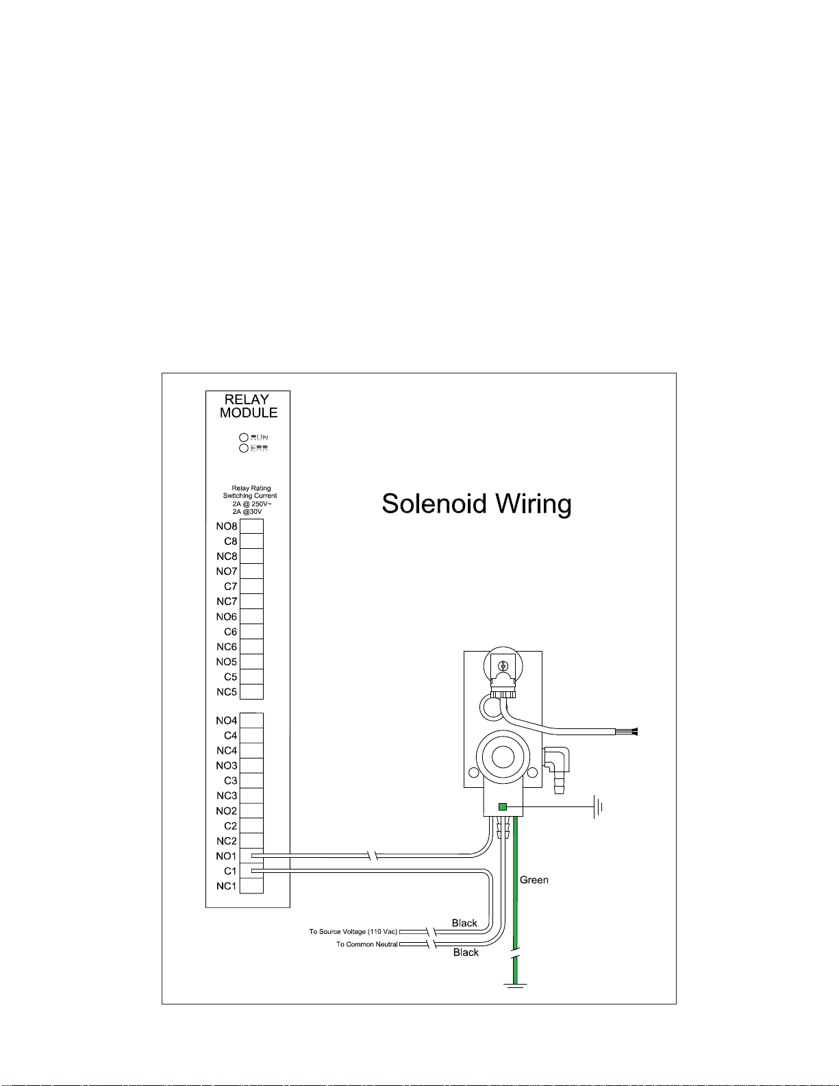
9. Inside the console, the TS-SCCM solenoid wiring must enter the console from the explosion proof rigid conduit through
a designated knockout on the non-IS side of the barrier inside. Connect the line, neutral, and ground wire of the
solenoid to a single unused channel on the Relay Module (RLY). The solenoid should be wired to the Common (C) and
Normally Open (NO) contacts of the channel selected. Source voltage (110 VAC) will need to be provided to the dry
contact relay.
Figure 5 – Solenoid Wiring
5
Page 11
Warning
console is positively shut down during installation and service. Failure to remove power may result
in damage to equipment, personal injury or even death.
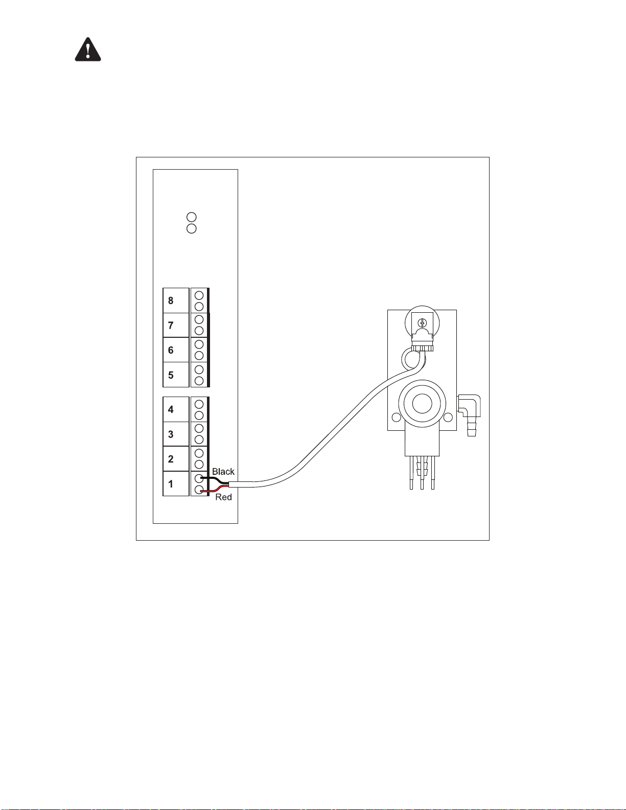
10. The TS-SCCM sensor wiring must enter the console in IS conduit through a knockout on the IS side of the barrier.
Secure each pair of sensor wires to a single channel on the 4-20mA Analog Input Module. Always use the next
available channel when wiring; for example, if Channels 1 – 3 are being used, Channel 4 must be used next. Pay
close attention to the polarity (+/-) of the wires.
4-20mA Input
Module
RUN
ERR
–
+
–
+
–
+
–
+
If using console power wires to provide power to a dry contact relay channel, ensure that the
–
+
–
+
–
+
–
+
Figure 6 – Vacuum Sensor Wiring
6
Page 12
SCM Setup (Console Programming)
The following instructions will guide you through SCM programming only. Administrator privileges will be necessary to
program the SCM application for the T5 FMS console. For instructions on FMS programming or on how to obtain an
Administrator access level, please refer to the T5 FMS Programming Guide (p/n 000-2142).
Access the T5 FMS console (via the LCD or Tank Sentinel Anyware - TSA) and navigate to the Setup Menu. Once at the
Setup Menu, go to each of the following sections and adjust SCM parameters accordingly. You will be prompted to enter
the Administrator access level when it is required.
Note: Sites setups vary depending on products used and other equipment installed. Setup information in the sections of
this chapter depict a typical site and are meant as examples only.
AC Input Module
The AC Input Module can accept incoming dispenser hook control signals. Hook signals are used to activate the STP via
the relay channel connected to the pump controllers. Control signals from the dispenser tell the console which product is
requested by the dispenser, then control signals activate the appropriate STP. To perform tests accordingly, SCM needs to
know when pumps/dispensers are being used by other applications.
Parameter Parameter Value
Active High If set to Yes, a high signal level will activate the channel and a low signal will deactivate the channel. If
set to No, then the channel is inverted and will only become active when a signal is absent and inactive
when a signal is present.
Channels Only select the total number of inputs intended for use.
Enabled If yes, will allow the channel to be mapped to another module. Other modules may use this signal to
trigger an event.
Name Should be a specic device from which the signal is originated.
Number Gasoline Hooks
per Dispenser
The number of product hook signal inputs to the console from the dispensers.
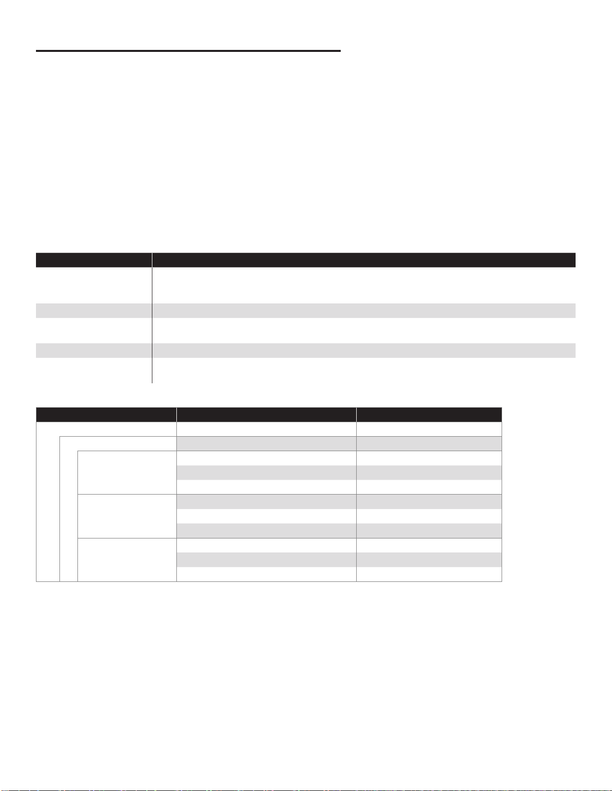
Example: AC Input Module SCM Setup
Group Name Parameter Name Parameter Value
AC Input Modules Number Gasoline Hooks per Dispenser 2
Module ‘#’ Channels ‘#’
Channel ‘#’ Name Disp 1 Unleaded Hook Signal
Enabled Yes
Active High Yes
Channel ‘#’ Name Disp 2 Unleaded Hook Signal
Enabled Yes
Active High Yes
Channel ‘#’ Name Disp 3 Unleaded Hook Signal
Enabled Yes
Active High Yes
7
Page 13
4-20mA Input Module
SCCM Vacuum Sensors use a single 4-20mA channel per sensor to accept an incoming signal that allows the console to
monitor secondary containment vacuum levels.
Parameter Parameter Value
Channels The total number of channels used for SCM, LLD, or other analog devices connected to the module.
Enabled Set to Yes.
Name Should be a specic device or location where the SCCM Vacuum Sensor is located.
Service Type Indicates the type of device sending the input to the console. Choose Secondary Containment Monitor to indicate
that the device is a SCCM 4-20mA Vacuum Sensor.
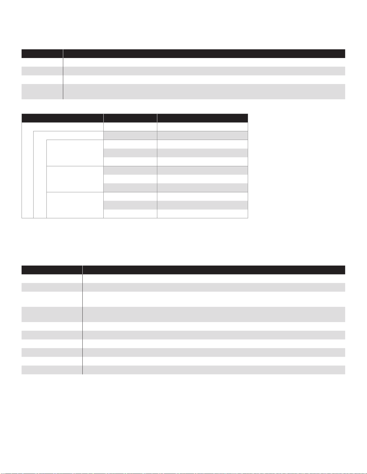
Example: 4-20mA Input Module SCM Setup
Group Name Parameter Name Parameter Value
4-20mA Input Modules
Module ‘#’ Channels ‘#’
Channel ‘#’ Name Regular SCCM Vacuum Sensor
Enabled Yes
Service Type Secondary Containment Monitor
Channel ‘#’ Name Premium SCCM Vacuum Sensor
Channel ‘#’ Name Diesel SCCM Vacuum Sensor
Enabled Ye s
Service Type Secondary Containment Monitor
Enabled Ye s
Service Type Secondary Containment Monitor
Relay Module
The Relay Module contains eight separate relays (called Relay Channels). A channel is used to open and close an
individual SCCM solenoid. For SCM, the solenoid relay channel is controlled by an input from the 4-20mA Input Module
(the SCCM Vacuum Sensor channel).
Parameter Parameter Value
Channels The total number of channels used for any equipment connected to the module.
Enabled Set to Yes.
Input Channel Select the 4-20mA Input Module channel connected to the SCCM vacuum sensor on the same SCCM as
the solenoid being programmed.
Input Type Select the 4-20mA Input Module that contains the SCCM vacuum sensor on the same SCCM as the
solenoid being programmed.
Logic Set to OR logic.
Name Should be a specic device or location of the SCCM Solenoid connected to the relay.
Number of Inputs Set to 1.
Physically Wired As Select Normally Open to indicate which contacts the solenoid is wired to.
Polarity Set to Normal.
Type Select Solenoid for type identify the type of device connected to the relay is a SCCM solenoid.
8
Page 14
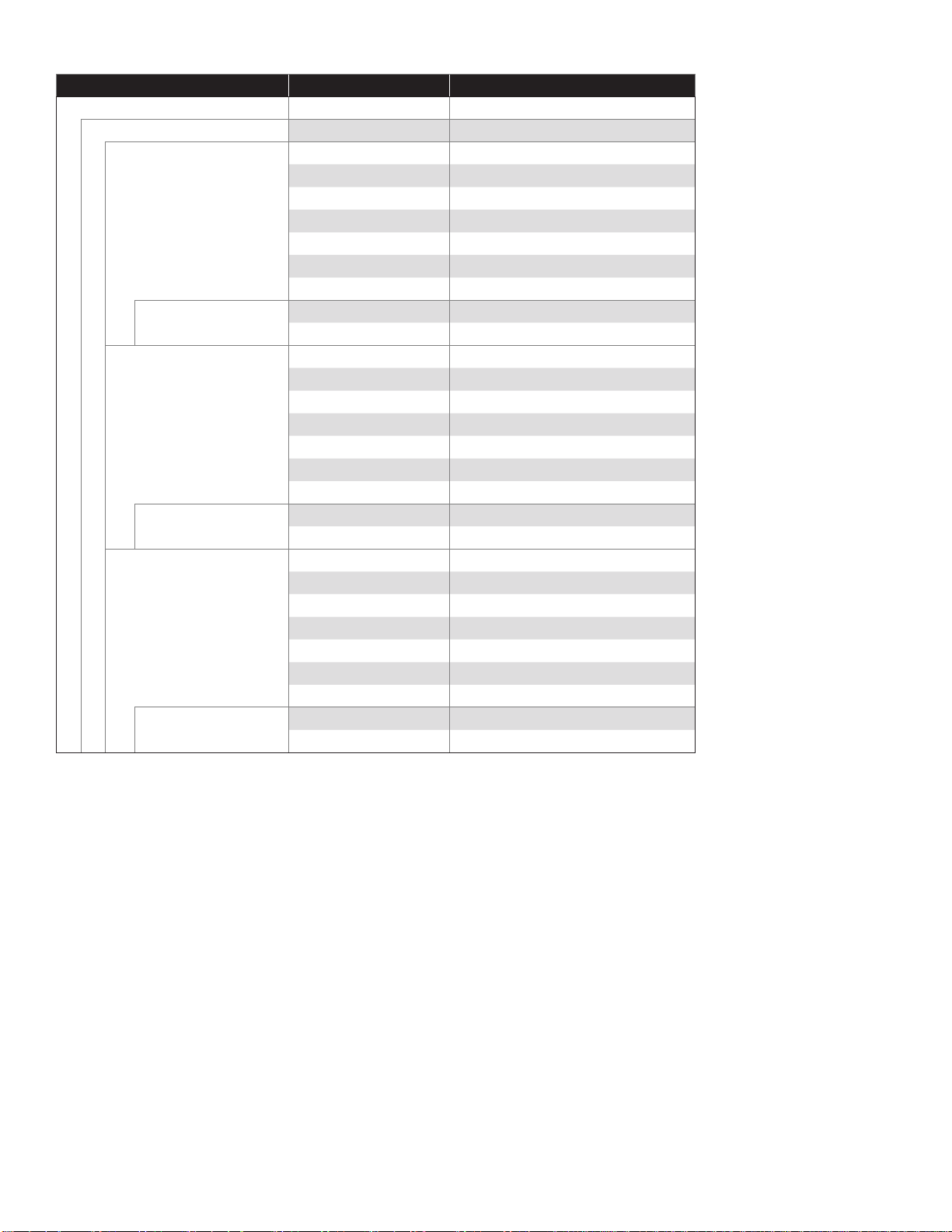
Example: Relay Module SCM Setup
Group Name Parameter Name Parameter Value
Relay Modules
Module ‘#’ Channels ‘#’
Channel ‘#’ Name Unleaded Solenoid Valve
Enabled Ye s
Type Solenoid
Polarity Normal
Logic OR Logic
Physically Wired As Normally Open
Number of inputs 1
Input ‘#’ Type 4-20mA Input Module
Channel Unleaded SCCM Vacuum Sensor
Channel ‘#’ Name Premium Solenoid Valve
Enabled Ye s
Type Solenoid
Polarity Normal
Logic OR Logic
Physically Wired As Normally Open
Number of inputs 1
Input ‘#’ Type 4-20mA Input Module
Channel Premium SCCM Vacuum Sensor
Channel ‘#’ Name Diesel Solenoid Valve
Enabled Ye s
Type Solenoid
Polarity Normal
Logic OR Logic
Physically Wired As Normally Open
Number of inputs 1
Input ‘#’ Type 4-20mA Input Module
Channel Diesel SCCM Vacuum Sensor
9
Page 15
Turbine Pump Interface (TPI) Applications (Alternate STP Control)
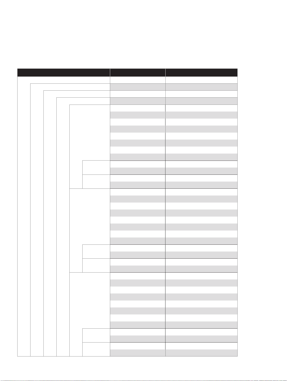
TPI is an alternative to using the Relay Module to actuate an STP on demand (from a dispenser request or SCM). Just
as with using a relay channel, this method will provide positive pump shutdown on alarm (if that option is chosen in the
setup). When using the standard TPI feature of the console to control a STP, be sure to map the SCCM vacuum sensor
as an “Input” for the STP that it is connected to (as shown in the TPI table). This will allow the SCM application to actuate
the STP when it is necessary to regulate the vacuum levels in the containment. For further information and instructions on
programming TPI and/or Relay Modules to control a STP, please refer to the T5 FMS Programming Guide (p/n 000-2142).
Example: TPI Setup
Group Name Parameter Name Parameter Value
Power Supply
RS-485 Enable Interface Ye s
TS-TPI Enable Interface Ye s
Controllers A Number of Controllers ‘#’
Controller ‘#’ Name Unleaded Controller
Enabled Ye s
Type Mag/Eco
Address 1
Group 0
Tank 1
Height 5.00 in
Number of inputs 2
Input 1 Type AC Input Module
Channel Unleaded Hook Signal
Input 2 Type 4-20mA Input Module
Channel Unleaded SCM Vacuum Sensor
Controller ‘#’ Name Premium Controller
Enabled Ye s
Type Smart I
Address 2
Group 0
Tank 2
Height 5.00 in
Number of inputs 2
Input 1 Type AC Input Module
Channel Premium Hook Signal
Input 2 Type 4-20mA Input Module
Channel Premium SCM Vacuum Sensor
Controller ‘#’ Name Diesel Controller
Enabled Ye s
Type Smart III
Address 3
Group 0
Tank 3
Height 5.00 in
Number of inputs 2
Input 1 Type AC Input Module
Channel Diesel Hook Signal
Input 2 Type 4-20mA Input Module
Channel Diesel SCM Vacuum Sensor
10
Page 16
Secondary Containment Monitoring Application
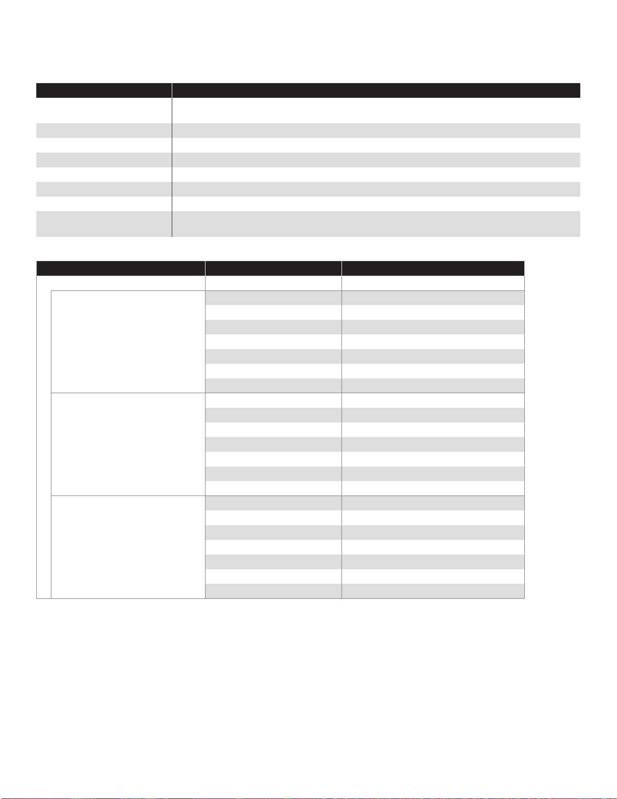
Programming the SCM application sets the parameters for SCM and enables it to monitor a set number of channels. Each
containment area or group must be programmed separately on the T5 FMS console.
Parameter Parameter Value
Auto-Enable on Reset A feature that allows the Containment area to enable itself after an alarm condition is cleared, or
when the system is powered on or reset.
Enabled Set to Yes.
Name Should be a specic location or product type of the containment area.
Number of Containments The number of SCCMs connected to the console.
Pump Shutdown on Alarm If set to Yes, provides positive pump shutdown when the containment area is in alarm.
Submersible Pump Channel Maps the containment area to the specic pump control output channel.
Submersible Pump Module Maps the containment area to a specic pump to provide pump on/off.
Transducer Maps the containment area to the SCM Vacuum Sensor as specied by the 4-20mA Input Module
channel assignments.
Example: SCM Application Setup
Group Name Parameter Name Parameter Value
Secondary Containment Monitor Number of Containments 3
Containment 1 Name Unleaded Line Containment
Enabled Ye s
Pump Shutdown on Alarm Yes
Auto-enable on Reset Yes
Submersible Pump Module Relay Module (or Power Supply for TPI)
Submersible Pump Channel Unleaded Pump Control
Transducer Unleaded SCCM Vacuum Sensor
Containment 2 Name Premium Line Containment
Enabled Ye s
Pump Shutdown on Alarm Yes
Auto-enable on Reset Yes
Submersible Pump Module Relay Module (or Power Supply for TPI)
Submersible Pump Channel Premium Pump Control
Transducer Premium SCCM Vacuum Sensor
Containment 3 Name Diesel Line Containment
Enabled Ye s
Pump Shutdown on Alarm Yes
Auto-enable on Reset Yes
Submersible Pump Module Relay Module (or Power Supply for TPI)
Submersible Pump Channel Diesel Pump Control
Transducer Diesel SCCM Vacuum Sensor
11
Page 17
SCM Status and Control Screens
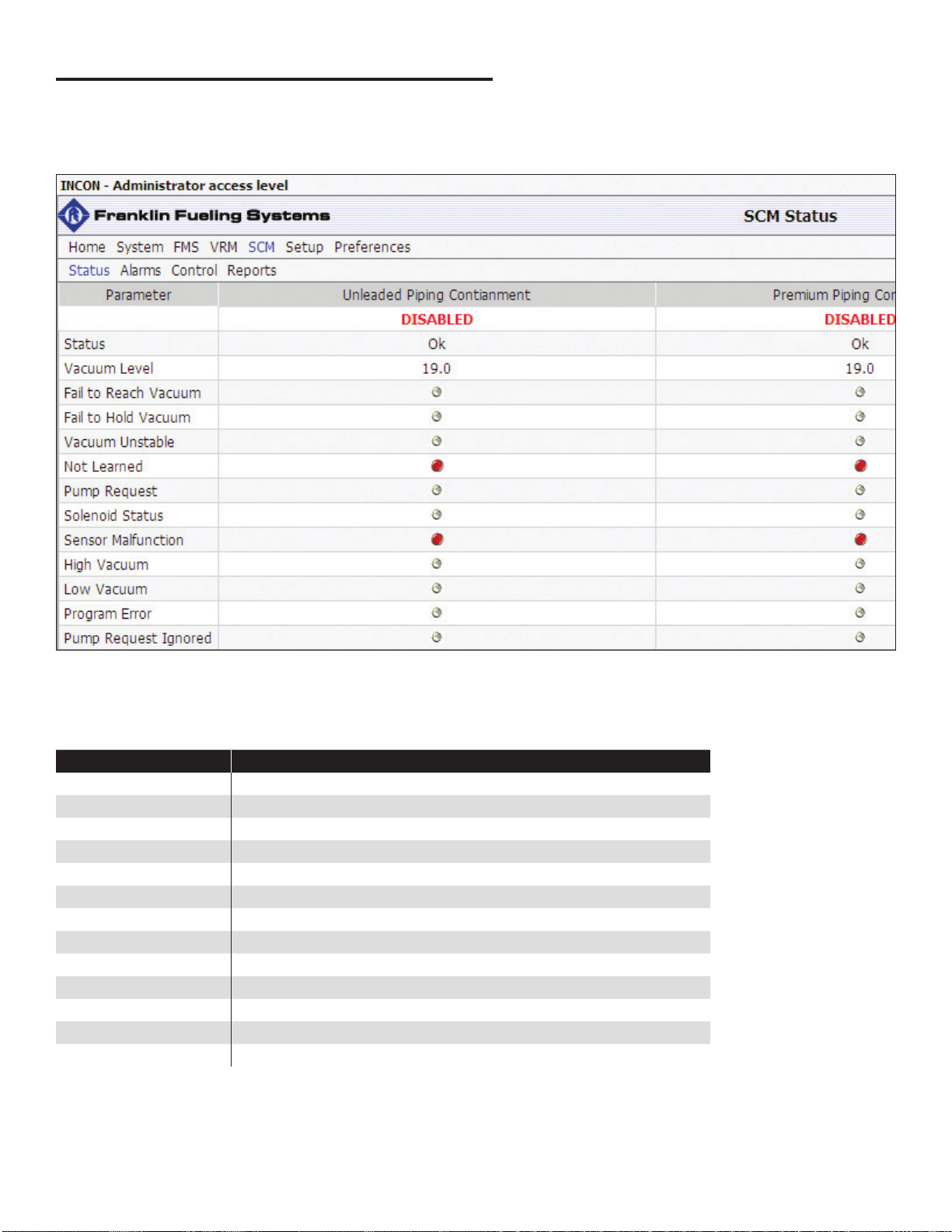
The status of each containment channel can be viewed at any time by navigating to the SCM Status or Control screens.
To get to the SCM Status or Control screens, go to SCM > Status (Summary) or SCM > Control (Containment).
SCM Status Summary Screen
When viewing the SCM Status Summary screen, remember to enable Auto Refresh. The Auto Refresh button will
allow the on-screen results to be automatically updated. When the results will update is dependent on the user-dened
parameter Refresh Rate found on the Conguration page.
Status and Alarm Indicators
Indicator Description
Fail to Hold Vacuum The containment will not maintain the learned level of vacuum.
Fail to Reach Vacuum The containment has not reached the learned level of vacuum.
High Vacuum The vacuum level of the containment has exceeded 9" Hg.
Low Vacuum The vacuum level of the containment has dropped below 1.25" Hg.
Not Learned The containment has not been learned.
Program Error SCM has encountered an error.
Pump Request SCM is attempting to cycle the pump on.
Pump Request Ignored The pump is being used by another application.
Sensor Malfunction SCM has detected a failure of the SCCM vacuum sensor.
Solenoid Status Indicates whether the normally closed SCCM solenoid is open or closed.
Status Indicates the condition of the containment.
Vacuum Level A direct reading from the SCCM vacuum sensor.
Vacuum Unstable The level of vacuum in the containment is not statistically sound.
For more information on alarms and troubleshooting, refer to the Alarms chapter in this manual.
12
Page 18
SCM Control Screen
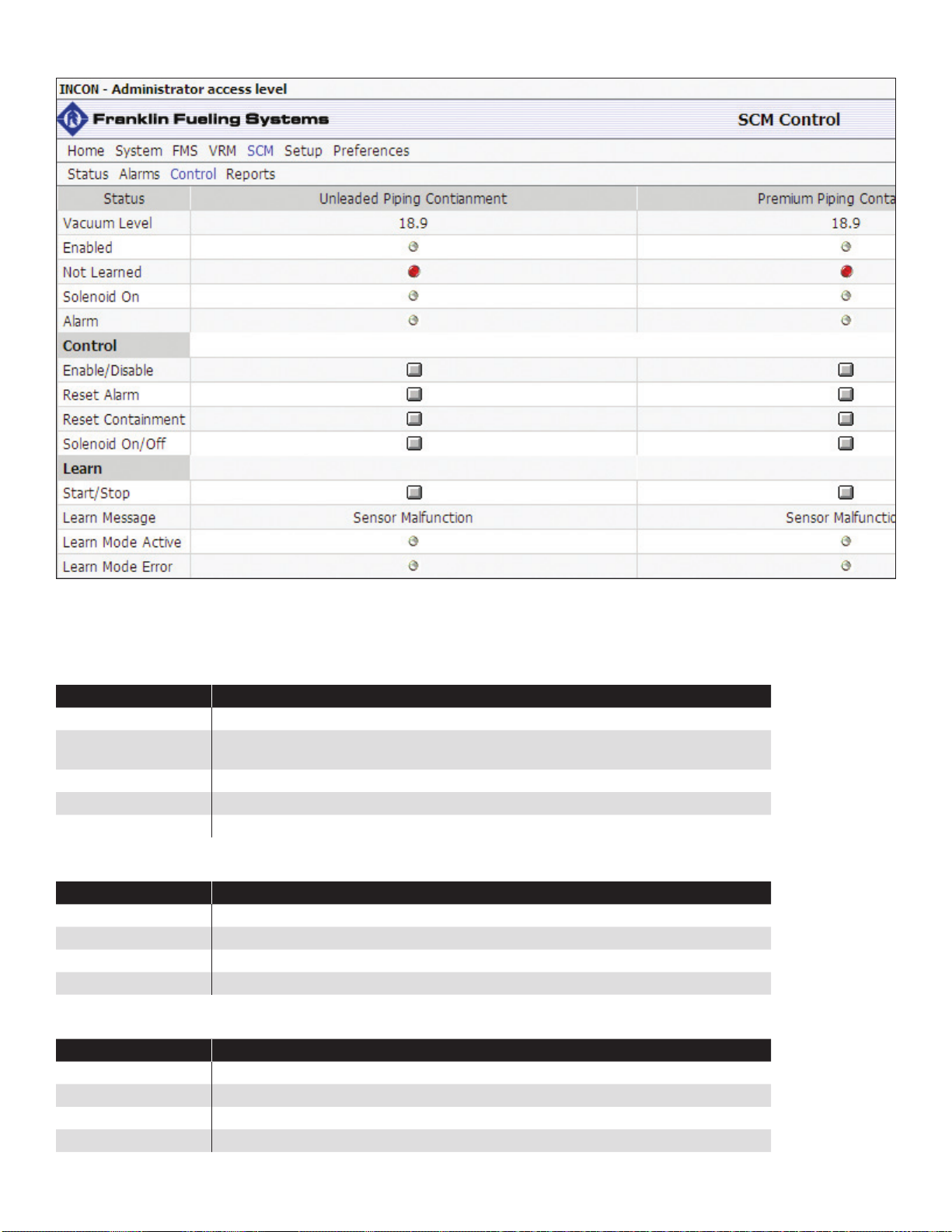
The SCM Control screen will automatically update containment information. Administrator privileges will be necessary to
access the SCM Control screen. For instructions on FMS programming or on how to obtain an Administrator access level,
please refer to the T5 FMS Programming Guide (p/n 000-2142).
Status Indicator Table
Indicator Description
Alarm The containment is in an alarm condition.
Enabled The containment has been enabled by the user or by the application automatically (if the
Auto-Enable on Reset parameter is turned on in the SCM Setup).
Not Learned The containment has not been learned.
Solenoid On Indicates whether the normally closed SCCM solenoid is open or closed.
Vacuum Level A direct reading from the SCCM Vacuum Sensor.
Control Indicator Table
Indicator Description
Enable/Disable Manually enable or disable the containment.
Reset Alarm Manually reset an alarm on the containment.
Reset Containment Manually reset the testing cycle of the containment.
Solenoid On/Off Manually cycle the solenoid on or off.
Learn Indicator Table
Indicator Description
Learn Message The status of the learning process.
Learn Mode Active The containment is being learned.
Learn Mode Error An error has been detected during the learning process.
Start/Stop Start or stop the learning procedure.
13
Page 19
Pre-Operational Containment Testing
Pre-operational containment tests determine the tightness of the entire SCM system, including TS-SCCM and interconnect tubing. These tests consist of two separate procedures: Containment Tightness Tests and STP Siphon Tests. The
rst procedure, Containment Tightness Testing, will determine whether the containment areas chosen to be monitored are
tight. The second, STP Siphon Testing, will determine if the STP is capable of creating enough vacuum for proper SCCM
operation.
The Containment Tightness Testing procedure assumes that all STP’s and pump controllers have been installed, wired,
calibrated, and are operational and in accordance with their respective installation and operation procedures. It also
assumes that all T5 FMS console programming has been completed.
Warning
Warning
Caution
Note: State and/or local laws may require a separate, more stringent containment tightness test. ALWAYS verify and
comply with local regulations.
Note: The STP connected to the SCCM being tested will need to be activated by lifting the appropriate product dispenser
handle. Verify that all STP’s and pump controllers are installed, calibrated and operational.
DO NOT apply vacuum or pressure until consulting the containment manufacturer on the maximum
allowed vacuum or pressure levels.
DO NOT use equipment that is not explosion proof in classied areas. Keep vacuum pumps
outside class 1, division 1, and class 2 areas. Refer to NFPA 30A, chapter 8.
DO NOT proceed to the Learn Process until each containment successfully completes
pre-operational testing. Failure to perform these tests or ignoring any failed tests may prevent the
SCM application from detecting a containment fault.
Required Equipment
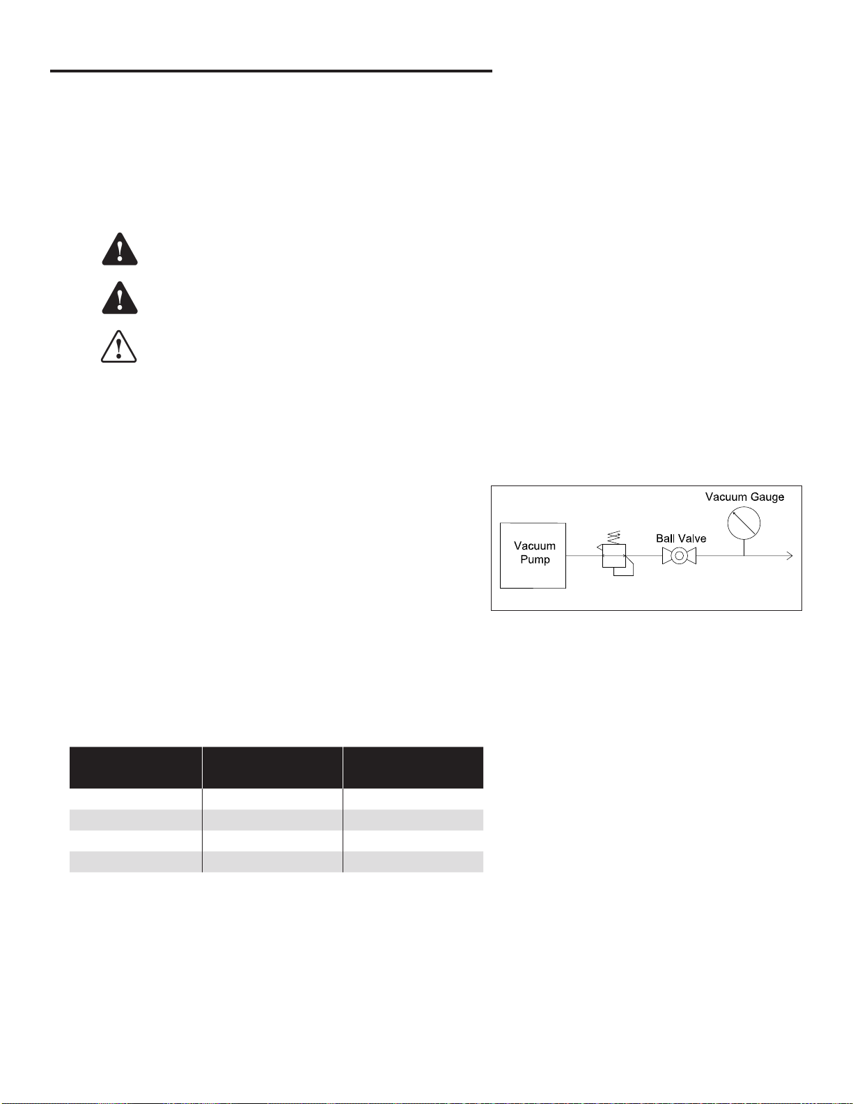
• Vacuum Pump (or other vacuum source)
• In-line Regulator
• Shut-off / Isolation Ball Valve
• Two 0" to -30" Hg Vacuum Gauge (2" Hg max. graduation marks)
• T-Fittings (where applicable)
In-Line
Regulator
Figure 7 – Vacuum Pump Setup Diagram
To Containment
Containment Tightness and Continuity Test
Perform the following steps for each SCCM channel.
1. Calculate the approximate containment volume for each area. Consult the secondary containment equipment
manufacturer’s manuals, data sheets, or other ofcial references.
APT SC Pipe Size
1.00" (XP-100-SC) 0.006 0.600
1.50" (XP-150-SC) 0.008 0.800
1.75" (XP-175-SC) 0.009 0.900
2.00" (XP-200-SC) 0.010 1.000
2. Vacuum Gauge Installation
• For Individual DW Turbine and Tank Sump Containments, connect the vacuum gauge as shown in Figure 7.
• For SC Pipe and Multiple Jumpered Containments, in addition to the setup shown in Figure 7, connect a vacuum
gauge to the end of the last interstitial space or pipe test boot.
Interstitial Volume
(gal/ft)
Interstitial Volume
(gal/100 ft)
14
Page 20

3. Install a vacuum gauge, regulator and isolation / shut-off ball valve in-line, onto the vacuum pump. With the ball valve
closed, power on the vacuum pump. Adjust the regulator to 6.5" – 7" Hg maximum. Power the vacuum pump off.
4. Remove the plug in the leak generator port on the SCCM. Connect the vacuum pump to this port.
5. Power the vacuum pump on. Open the isolation ball valve slowly to evacuate the containment area to 6" Hg. Close the
isolation ball valve:
• If the vacuum level does not increase after 30 seconds while the vacuum pump is running; large
containments may take up to 10 minutes. Inspect each component for leaks.
• If the gauge drops below 6" Hg immediately after closing the valve then steadies before zero.
Slowly open the isolation ball valve again to evacuate the containment to 6" Hg. Repeat as
necessary until containment remains at 6" Hg and close the isolation ball valve.
• If the gauge immediately drops to zero. This indicates that a leak exists. All leaks must be
identied and repaired before continuing this test.
Note: Vacuum leaks can be identied by pressurizing the containment area per the manufacturer’s specied levels, then
spraying a solution of water and liquid soap on connections and ttings. Consistent bubbling on soaped connections/ttings will give a visual indication of the source of a leak. Consult the manufacturer’s documentation for
appropriate pressure levels.
6. Once a stable vacuum level is reached (4.5" – 7" Hg on the vacuum gauge
in-line with the vacuum pump), record the level. Use the table to the right
to determine the required wait time. The containment vacuum level should
remain stable throughout the entire wait time; the vacuum pump may be shut
off at this point.
If the vacuum level drops more than 1" Hg during the required wait time, then
the containment failed the test. All leaks must be identied and repaired rst,
then the Containment Tightness Test should be repeated until it successfully
completes.
Containment Wait Time Table
Containment
Volume
0.25 – 5 gal 15 min
5 – 50 gal 30 min
50 – 100 gal 60 min
100 – 250 gal 2 hr
250 – 500 gal 4 hr
Wait Time
7. If a vacuum gauge has been installed at the end of the system, compare the
gauge reading with the console. If the measurements are not within ±2" Hg, a blockage may exist within the
containment and/or between the SCCM and vacuum gauge. All blockages must be identied and corrected. Once the
blockage is corrected, restart the Containment Tightness Test.
8. Uninstall the vacuum pump, regulator, isolation / shut-off valve and vacuum gauges at this time. Continue on to the
STP Vacuum Test in the next section. Do not replace the Leak Generator Port Plug.
15
Page 21

STP Siphon Flow Rate Test
Warning
Note: During this procedure the containment reaches 9" Hg, which will cause the console to display a High Vacuum
alarm and disable the containment. If Pump Shutdown on Alarm is chosen in the options, a disabled containment
will not allow the STP to be activated. Navigate to the SCM Control screen, press Reset Alarm to continue.
1. Install a vacuum gauge and the vacuum leak generating device (TS-SCMCAL) into the leak generator (LG) port on the
SCCM using necessary ttings. Switch the toggle valve to the UP (open) position.
2. At the T5 series FMS console (using either the LCD or Tank Sentinel Anyware), navigate to the SCM Control Menu.
Press the Solenoid button — this activates (opens) the solenoid.
3. Activate the STP by lifting the appropriate dispenser handle.
4. With the STP on and the toggle valve open, the vacuum level must be able to reach at least 6.5" Hg. Verify vacuum
levels at the gauge connected to the containment area.
Large Containments (>50 gal.) may take several minutes. For large containments, close the leak generator until the
vacuum level reaches approximately 6" Hg. Open the leak generator. Allow the vacuum to build. The vacuum level
must be able to reach at least 6.5" Hg, but, if the vacuum is not able to reach at least 6.5" Hg, then the STP siphon
assembly must be repaired or replaced.
5. Once the vacuum level is veried above 6.5" Hg, return the hook signal to turn off the STP.
6. At the T5 series FMS console (LCD or TSA), navigate to the SCM Control Menu. Press the Solenoid button — this
deactivates (closes) the solenoid.
Failure to open the leak generator (TS-SCMCAL) during this test can apply an excessive vacuum
level to the containment, causing irreversible damage. Ensure that the leak generator is installed
properly and that the toggle switch is in the OPEN position prior to energizing the STP.
7. Allow the vacuum to decay to 0" Hg.
If you are proceeding to the Learn Process chapter next, the TS-SCMCAL may remain installed at the SCCM leak
generator port.
16
Page 22
Learn Process
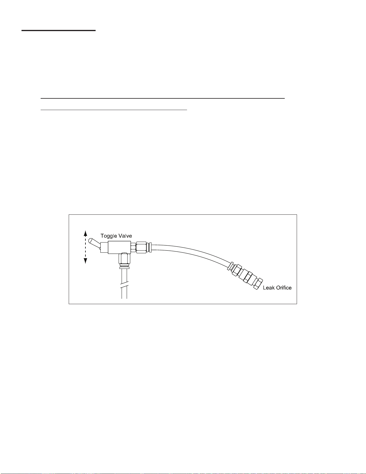
Each containment area must be Learned before the SCM system can continuously monitor it. Learning involves
evacuating the containment area, then introducing a calibrated leak using the Leak Generating Kit (TS-SCMCAL). The
system learns what the evacuation and decay curves look like by employing this process. The system then uses the
curves it’s learned to determine if there is a leak while it monitors the containment area.
Note: All console programming must be completed prior to the learn process. Refer to the SCM Setup (Console
Programming) chapter in this manual for details. Administrator privileges are necessary to Learn containments.
Refer to T5 FMS Programming Guide (p/n 000-2142) for information on gaining Administrator privileges.
Note: Complete the Pre-Operation Containment Testing chapter prior to starting the Learn Process.
Note: No dispensing can take place during the Learn Process. If product is dispensed while Learning, stop the process
by pressing the Reset button. Always restart the Learn Process from the beginning.
Note: DO NOT submerse or block the TS-SCMCAL orice while learning the containment. The orice MUST be kept free
of dirt and debris.
When to Learn/Re-Learn
• SCM installation and start-up
• After repairs or modications to containment areas
• After repairs or modications that may affect the siphon ow rate
• After 4-20mA Input Module replacement
• After certain 4-20mA Input Module rmware upgrades (consult FFS Technical Services Department)
• If moving the SCCM to another 4-20mA channel
• When adding or removing volume from a containment
off (closed)
on (open)
Figure 8 – Leak Generator Kit (TS-SCMCAL)
Procedure
1. The SCCM leak generator port is plugged for normal operation but may have been removed for pre-operational testing.
If the leak generator port is plugged, remove the plug.
2. Install a TS-SCMCAL at the leak generator port on the SCCM; the TS-SCMCAL may remain installed from the Pre-
Operational Containment Testing chapter.
3. Switch the toggle valve to the Up (closed) position.
4. At the T5 series FMS console (LCD or TSA), navigate to the SCM Control screen. Verify that the console is indicating
less than 0.2" Hg before the containment is Learned. If the vacuum level is above 0.2" Hg, open the toggle valve to
equalize containment vacuum to 0" Hg. Close the toggle valve when the containment is below 0.2" Hg.
5. Press/Click the Learn button. SCM will activate the pump and open the solenoid valve. The vacuum level of the
containment should rise and the Learn Message should display Learning Evacuation Curve. When the vacuum
reaches 6" Hg, the solenoid will close and the STP will turn off. The solenoid may cycle on and off during evacuation,
which is part of its normal operation during this procedure.
17
Page 23

6. When the message Open Leak Toggle Valve appears, switch the toggle valve to the UP (open) position. SCM will learn
the vacuum decay curve and display Learning Decay Curve on-screen. The vacuum level will begin to fall.
7. When nished, the message Learn Completed – No Errors is displayed on-screen and the Not Learned indicator will
become inactive.
Note: If any errors are encountered at any time during the Learn Process, the screen will display the appropriate error
message and the Not Learned indicator will be active. Refer to the Alarms chapter of this guide for information on
troubleshooting any errors that are displayed.
8. Once the containment has been successfully learned, enable the containment on the Containment Control screen with
the leak generator open. The console will automatically begin a test on the containment. This test should fail, forcing
the containment into alarm status.
9. Close the leak generator. To clear the alarm, navigate to the Containment Control screen and choose Reset Alarm. If
the Auto-enable on Reset option is turned on in the SCM section of programming, the containment will be automatically
enabled after resetting the alarm condition and will automatically begin a test on the containment. This test should
pass, allowing SCM to continue to monitor the containment. If this test fails, isolate why the test failed, make necessary
repairs, and then retry the test.
10. Remove the leak generator and replace the leak generator plug. Apply TFP tape sealant to the threads of the plug,
then tighten the plug. If alarms or errors occur, refer to the Alarms chapter of this guide. When the condition is
corrected, restart the Learn Process.
Learn Messages
Learn Message Description
Existing Vacuum Detected The Learn Process was started with .5" Hg or more existing in the containment. The Learn Process
needs to be restarted at 0" Hg.
Learned The containment has been Learned with no errors.
Learning Decay Curve Displayed during the Learn Process to indicate that the calibrated leak decay curve is being recorded.
Learning Evacuation During the Learn Process, SCM is recording the time and vacuum levels while evacuating the
containment.
Failed to Reach Target
Vacuum / Time Limit
Exceeded / Pre-Existing Leak
No Leak Detected Vacuum level is constant or has risen while Learning the decay curve.
No Leak Detected/Time Limit
Exceed
Not Learned The containment has been programmed, but the containment has never been Learned. Refer to the
Open Leak Valve This is a required step during the Learn Process. When shown, open the leak generator.
Pump Request Ignored SCM sent a request to start the STP, but the TPI or the relay module didn’t send conrmation that the
Sensor Malfunction This message is displayed if the containment is enabled in the setup, not Learned, and the sensor
Exceed Time Limit to Reach
Target Vacuum
Time Out for Leak Valve Not
Opened
A vacuum leak is present when the leak generator should not be open.
The leak valve was opened when prompted, but the leak valve was closed before the Learn Process
was completed. Restart the Learn Process and open the leak valve when prompted. Close the leak
valve after the Learn Process has completed.
SCM Learn Process section to Learn the containment. Follow all Warnings, Cautions, and Notes prior
to Learning the containment.
STP was running. The STP may be used or disabled by other applications.
was disconnected. Verify sensor wiring.
Evacuation Learning exceeds the limit.
The leak valve is not open during the Learn Process. Restart the Learn Process and open the leak
valve when prompted to by the console.
18
Page 24
SCM Reports
SCM reports are available on demand from the console locally or remotely (with TSA). Several report options may be
used to print or save generated reports. For more information on reports in general, please refer to either the T5 Series
Programming Manual (p/n 000-2142) or the T5 Series Operator’s Guide (p/n 000-2151).
SCM Alarm Reports
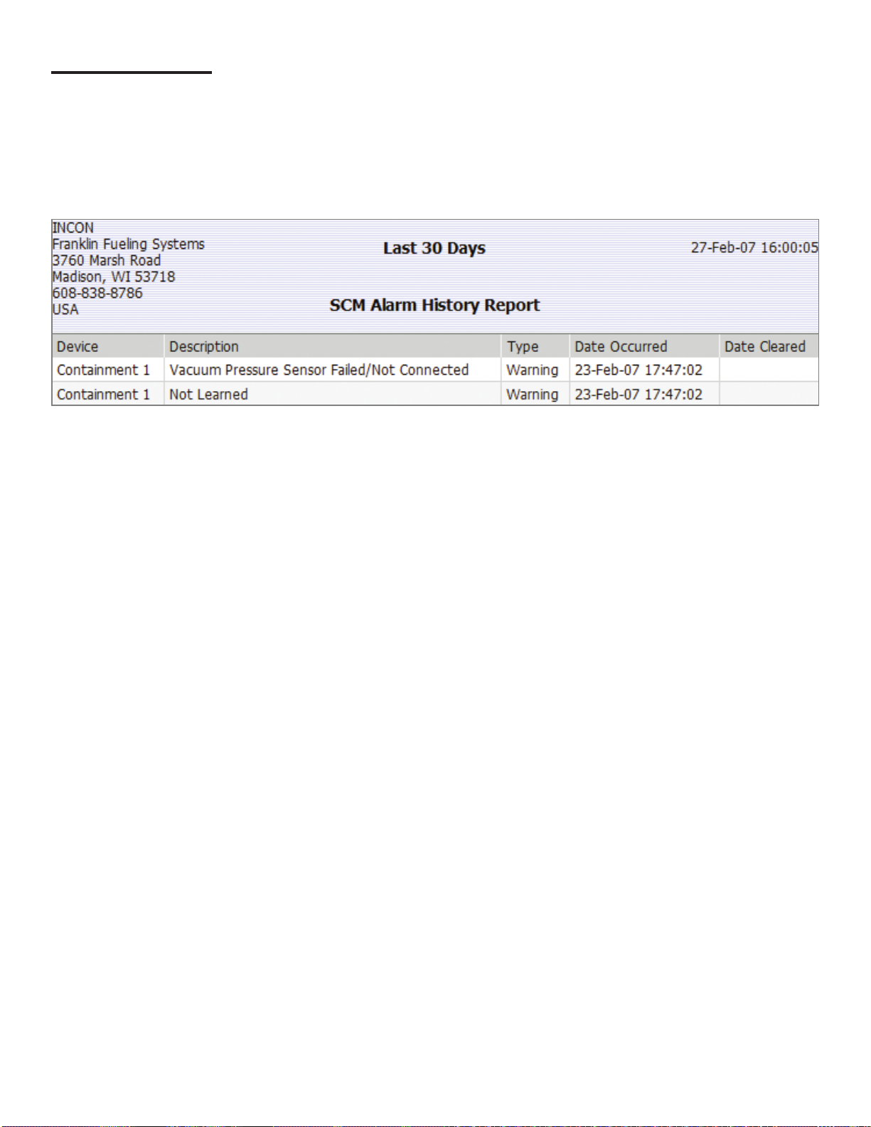
SCM Alarm Reports include any SCM alarms or application events that occurred within the date range chosen by the
user. An example of an SCM Alarm History Report can be found below.
Application Event Reports
Application Event Reports include any system warning pertaining to SCM equipment that occurred within the date range
chosen by the user.
19
Page 25
Alarms
When a T5 FMS console is in alarm, the Alarm LED on the front of the console will ash. If SCM has been programmed
to shut down the pump on alarm (in the SCM Setup), the pump will be unavailable for all system tests and dispensing
until the containment with the active alarm is manually Reset. If the condition still exists after reset, the alarm will return. A
service visit may be required to identify and correct the condition.
Warning
Always REMOVE POWER from the console prior to installing/removing a module or performing any
maintenance while the console door is open.
Note: Refer to the Important Safety Messages outlined in the beginning of this manual before performing any console
maintenance.
Note: If at any time while troubleshooting a Warning or Alarm this guide is not able to help you correct the issue, please
contact FFS Technical Services.
SCM Alarms and Warnings
To troubleshoot your alarm or warning, identify the Alarm/Warning display on the console in the table below and review the
solution presented in the Error Code Table that follows.
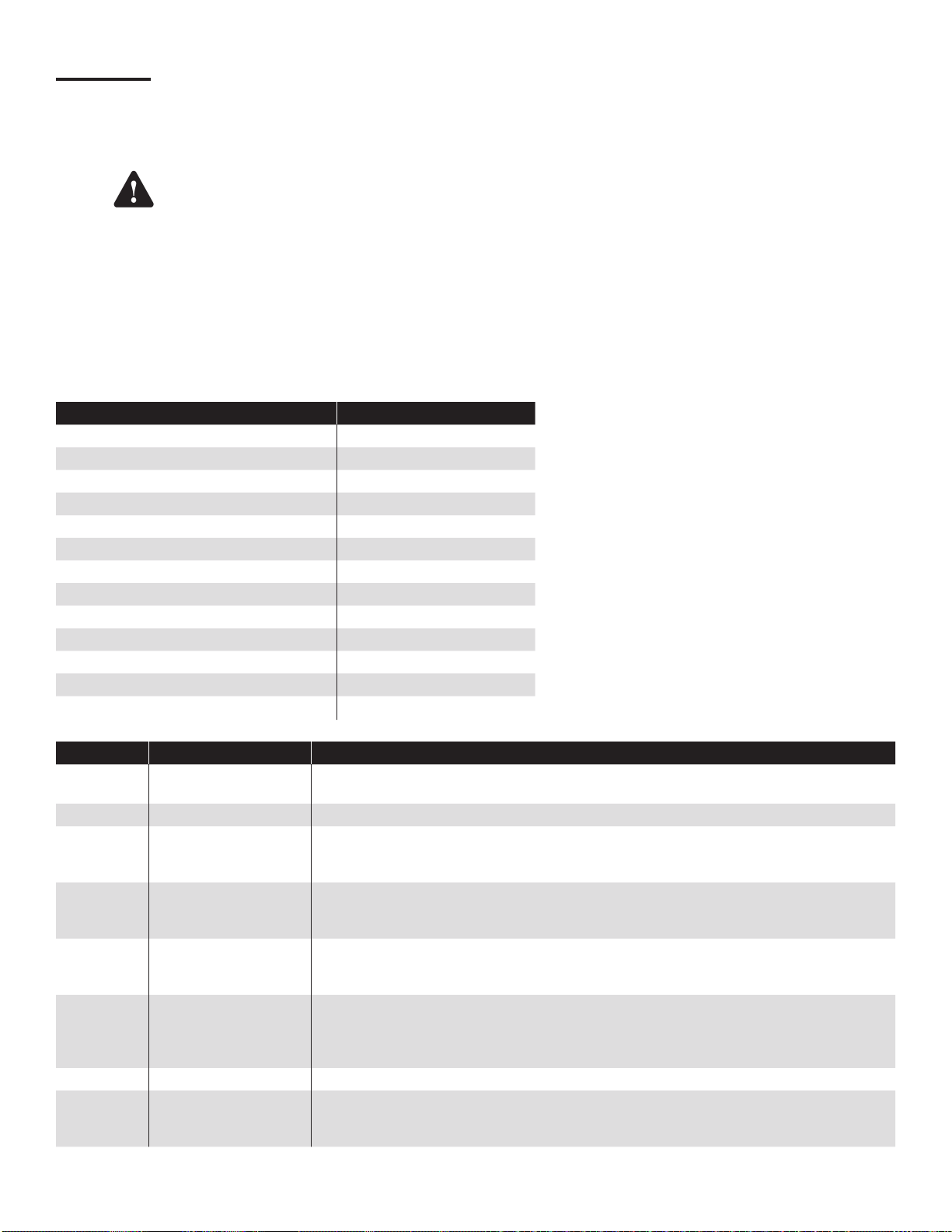
Alarm/Warning Possible Error Codes
Channel Not Learned G
Failed to Hold Vacuum A, B, H
Failed to Reach Target Vacuum A, B, C, D, F
Low Vacuum A, B, C, D, F
Low Vacuum and Pump Request Ignored A, B, F, G
Not Congured G
Not Learned G
Program Error Detected Check SCM Programming
Pump Request Ignored F
Unstable Vacuum B, D, C
Vacuum Sensor Failure E
Vacuum Sensor Failure / Not Connected E
Vacuum Too High B, G
Error Code Error Solution
A Containment Tightness Refer to the Containment Tightness Testing section of this guide and perform the tests in
that section to ensure that there are no leaks and that the tank is tight.
B Thermal Contraction Caused by temperature variations of the air (or liquid if present) in the containment.
C Liquid in Containment This will decrease the containment size. If liquid is drawn through the containment, through
the STP siphon, various parameters and containment vacuum readings will be incorrect.
Containments should remain free of liquid at all times.
D Siphon Function Check The siphon must be able to pull a vacuum of 8" Hg or more if connected to other equipment.
The vacuum also must have a minimum ow rate of 146 L/Hr. Perform a STP Siphon Flow
Rate Test as illustrated in the Pre-Operational Containment Testing chapter.
E SCCM Vacuum Sensor
Function Check
F STP Function Check Use the dispenser to signal the STP when the dispenser is authorized then the STP should
G Verify Programming Refer to the SCM Setup chapter of this guide for all SCM related programming information.
H SCCM Vacuum Relief
Valve Function Check
The transducer is sending incorrect data or no data to the console. Verify wiring from the
transducer to the console. If wiring is correct, setup and program the transducer on a
different, unused channel for testing.
run. Also, SCM must be able to signal the STP pump on. Force a test on the containment
using the SCM Control screen. The STP will start only if necessary to evacuate the
containment. If the STP does not run to evacuate the containment, verify programming.
The mechanical vacuum relief valve is designed to open when containment vacuum levels
reach or exceed 10" Hg. If at any time the containment vacuum level exceeds 10" Hg while
the pump is on, this error will occur as an indication of a relief valve failure.
20
Page 26

Clearing Alarms
Clearing a console of alarms is important because, depending on how the T5 FMS console has been set up, alarms can:
disable channels, start an annunciator, or stop an SCM test under way.
Administrator privileges will be necessary to clear SCM alarms on the T5 FMS console. For instructions on how to obtain
an Administrator access level, please refer to the T5 FMS Programming Guide (p/n 000-2142).
1. Identify the alarm on the SCM Alarms screen.
2. Diagnose the condition using information found in the Alarms chapter of this guide.
3. Follow the troubleshooting steps in the previous section of this chapter to correct the issues indicated by the alarms.
4. Navigate to the SCM Control screen.
5. Select Reset Alarms on the Control screen.
6. If Auto-Enable on Reset is chosen in the SCM Setup, then the containment will enable automatically. Otherwise, select
Enable/Disable on the Control screen.
If the condition still exists, the alarm can take up to several hours to reappear after the containment is enabled.
21
Page 27

Enabling/Disabling SCM
After learning the channel(s), each channel will need to be enabled to allow containments to be monitored. The
Containment Status reects the current status of the channel.
Enabling SCM Channels
At the T5 FMS console (LCD or TSA), navigate to the SCM Control screen. Press the Enable/Disable button to enable
the channel.
Only while the channel is enabled will that channel continuously monitor and test vacuum levels by activating the STP
as necessary. Normal SCM operating vacuum level is between 2" Hg and 5" Hg. During vacuum recharge periods, it is
normal for the vacuum levels to reach 6" Hg.
Note: A channel will not enable properly if it is not learned, in an alarm status, or if an error condition exists (such as a
sensor malfunction). An alarm must be reset to enable a SCM channel.
Disabling SCM Channels
At the T5 FMS console (LCD or TSA), navigate to the SCM Control screen. Press the Enable/Disable button to disable
the channel.
Important: While the channel is Disabled, SCM will neither maintain nor test containment vacuum levels.
Disabling the channel will force the console to display a Containment Not Enabled warning. This warning will also appear
on the SCM History Report. The channel may be re-Enabled at any time.
If alarms or errors occur, please refer to the Alarms chapter of this guide.
22
Page 28

SCM Annual Functional Testing
Perform a SCM Functional Test annually. This test will verify that the SCM application will detect and alarm on a leak
condition. This test should be performed during times when there is no dispensing.
1. If the channel is Enabled, disable the channel. At the T5 FMS console (via LCD or TSA), navigate to the SCM Control
screen. Press the Enable/Disable button to disable the channel.
2. Remove the plug in the Leak Generator (LG) port on the SCCM. Connect the TS-SCMCAL (Leak Generator Kit) to this
port.
3. Switch the toggle valve to the DN (closed) position.
4. Enable the channel. Wait for the containment vacuum levels to reach normal operating levels.
5. Switch the toggle valve to the UP (open) position.
6. The vacuum levels will then fall, which could take several minutes for large containments. Verify that the console
displays an alarm.
7. The channel will be disabled by the SCM application. Remove the TS-SCMCAL. Apply TFP tape sealant to the threads
of the Leak Generator Port Plug. Replace and tighten the plug.
8. At the T5 FMS console (via LCD or TSA), navigate to the SCM Control screen. Press the Reset Alarm button to
enable the channel, then press the Enable/Disable button to enable the channel. Resume normal operation.
9. If the SCM Annual Functional Test passed, please skip this step. If the system did not catch the leak and the test failed,
disable the channel and run the pre-operational tests. Perform the annual test again. If the channel still fails to detect
the leak, please contact FFS Technical Support.
23
Page 29

Page 30
©2013 FFS 000-0528 Rev. E
Page 31

 Loading...