

Page 1
INSTALLATION AND
PROGRAMMING MANUAL
FOR MODEL
1250-LTC
PROGRAMMABLE POSITION MONITOR
Solid State Indicator for SynchroTransmitter
000-2072 Rev. C
1
Page 2

INTELLIGENT CONTROLS, INC.
PO Box 638
Saco, Maine 04072 USA
Phone: 207-283-0156 FAX: 207-283-0158
Toll Free: Technical Service & Sales 800-872-3455
Web Site: www.incon.com E-mail: sales@incon.com
This manual applies to all INCON model 1250-LTC monitors
Copyright 2008, Intelligent Controls, Inc. All rights reserved
.
2
Page 3

TABLE OF CONTENTS
Section: Page:
List of Figures…………………………………………………………………… 4
List of Tables……………..……………………………………………………… 4
Introduction……………………………………………………………………... 5
1.0 Installation……………………………………………………………..…… 5 - 8
2.0 Programming…………………………………………………………..…… 9 – 33
2.1 Front Panel Programming…………………………………………….. 9
2.2 Serial Port Programming – ASCII …………………………………… 13 - 17
2.3 Serial Port Programming – MODBUS……………………………….. 18 – 33
2.3.1 MODBUS Packet Format – Read……………………………….. 19
2.3.2 MODBUS Packet Format – Write………………………………. 20
2.3.3 MODBUS Packet Format – Error Exception Response……….. 21
2.4 Operating Modes………………………………………………………. 34 – 37
2.5 Programming Notes……………………………………………………. 38
3.0 Options…………………………………………………………………..….. 39 – 48
3.1 Analog Output……………………………………………………..…… 39
3.2 High / Low Relay Limits………………………………………..……… 40 – 45
3.2.1 Tap Change Acknowledgement.………………………………… 41
3.2.2 High Tap / Low Tap……………………………………………… 41
3.2.3 Total Tap Change Count………………………………………… 42
3.2.4 On-Tap Alarm……………………………………………………. 42
3.2.5 Up-To & Down-To Count………………………………….…….. 44
3.2.6 Pass-Through-Neutral Alarm…………………………….……… 44
3.2.7 One-Direction Change Count…………………………….……… 45
3.2.8 FA 25 & FA 27 Error Alarm…………………….…………….… 45
3.3 Serial RS-232…………………………………………………...……….. 46
3.4 Serial RS-485 .……………………………………...………………….... 47
3.5 Input Isolation…………………………………………………...……… 48
4.0 Field Calibration and Test………………………………………...…….…. 48 – 49
5.0 Error Codes…………………………………………………………….……. 50
6.0 Specifications…………………………………………………………….….. 51
3
Page 4

LIST OF FIGURES
Figure: Page:
1.1 Mechanical Dimensions…………………………………………………………… 6
1.2 Field Wiring Diagram…………………………………………………………….. 6
1.3 Field Wiring Diagram with 4-20mA Option.…………………………………….. 7
2.1 Simplified Programming Flowchart…...…………………………………………. 12
2.2 Serial Data Dump Example……………………………………………………….. 17
2.3 Base 1 Uni-Polar Mode Analog Output………………………………………….. 35
2.4 Base 0 Uni-Polar Mode Analog Output………………………………………….. 36
2.5 Bi-Polar Mode Analog Output…………………………………………………… 37
3.1 Relay Field Wiring Diagram……………………………………………………... 40
3.2 On-Tap Example………………………………………………………………….. 43
4.1 Analog Output Adjustment Pots…………………………………………………. 49
LIST OF TABLES
Table: Page:
1.1 Terminal Functions……………………………………………………………… 7
1.2 DIP Switch Functions…………………………………………………………... 7
1.3 Analog Output Configuration Jumpers…………………………………………. 8
2.1 Numeric and Alpha-numeric Menu Items……………………………………… 9-12
2.2 Serial Programming ASCII Commands……………………………………….. 13-15
2.3 Read Registers Command Format..……………………………………………. 19
2.4 Read Registers Response Format.…………………………..………………….. 19
2.5 Write Registers Command Format……………………………………………... 20
2.6 Write Registers Response Format……………………………………………… 20
2.7 Error Exception Response Format……………………………………….…….. 21
2.8 RS-485 MODBUS Register Definitions...……………………………………… 22-33
3.1 Analog Output Load Limits……………………………………………………. 39
3.8 Wiring: Digital Connector Pin-Out……………………………………….…….. 47
5.1 Error Codes …………………………………………………………….….……. 50
4
Page 5

INTRODUCTION
The Model 1250-LTC Programmable Position Monitor is a highly advanced solidstate instrument, which measures the absolute position of a synchro transmitter. It provides
both a user definable visual panel indication and optional analog and digital signal outputs
suitable for a variety of monitoring and control applications.
The INCON 1250-LTC series is unique in its capability to monitor up to 40 userdefinable position segments. It is specifically designed for monitoring power transformer
load tap changer position, where the desired readout is in whole tap numbers. Its transmitter
can be attached to any operating shaft on the LTC and the 1250 programmed to read out in tap
positions. The display and all outputs follow a “stair step” function defined in the program.
The INCON 1250 has become the industry standard for LTC position monitoring.
In addition to basic LTC tap position, the 1250-LTC can provide useful information
about the movement of the LTC. Beginning with a momentary (optional) relay closure after
each successful tap change, the 1250-LTC keeps records on seven important issues relating to
LTC movement, including: total number of tap changes; number of days since last “pass
through neutral”; number of changes “up to” and “down to” each tap; and more.
Most LTC’s rotate about 9 to 11 degrees with each tap change. The 1250-LTC can
measure in increments of 1/10th of a degree. A special feature of the 1250-LTC is its ability
to monitor small discrepancies in tap position. A programmable limit can be set to give an
alarm when the discrepancy in tap position reaches the limit. Inaccurate tap position can be
an early indicator of wear in the LTC mechanism or possible impending failure.
The 1250-LTC may be wired in parallel with existing synchro transmitter/receiver
pairs or wired directly to the synchro transmitter. Additional 1250’s may be wired to the
same transmitter without compromising the accuracy or reliability of the system.
1.0 INSTALLATION
• The Model 1250-LTC is designed for use in any 50/60 Hz, five-wire synchro system
compatible with electrical specifications given in Section 6.0, page 51. These devices
include CX, TX, CDX, and TDX function synchros, as well as Self-Synchronous
Indicator devices. (INCON’s model 1292 Synchro is a highly specified robust
transmitter with a history of proven performance.)
• The panel-mount case is designed to snap-fit into a standard 1/8 DIN rectangular
cut-out of 44mm (1.73 in.) by 92mm (3.62 in.)
• Wiring is done to the rear of the case. #16 AWG (min.) type THHN, THWN, TFFN,
or equivalent wire is recommended for the five AC synchro lines. #20 AWG (min.)
shielded twisted pair wire is recommended for analog output wiring. Use appropriate
spade lugs (provided) when connecting to the case terminals.
• Contact INCON Technical Service (1-800-872-3455) for application assistance if the
synchro transmitter and the 1250-LTC monitor are separated by a wire run of more
than 1200 feet.
5
Page 6
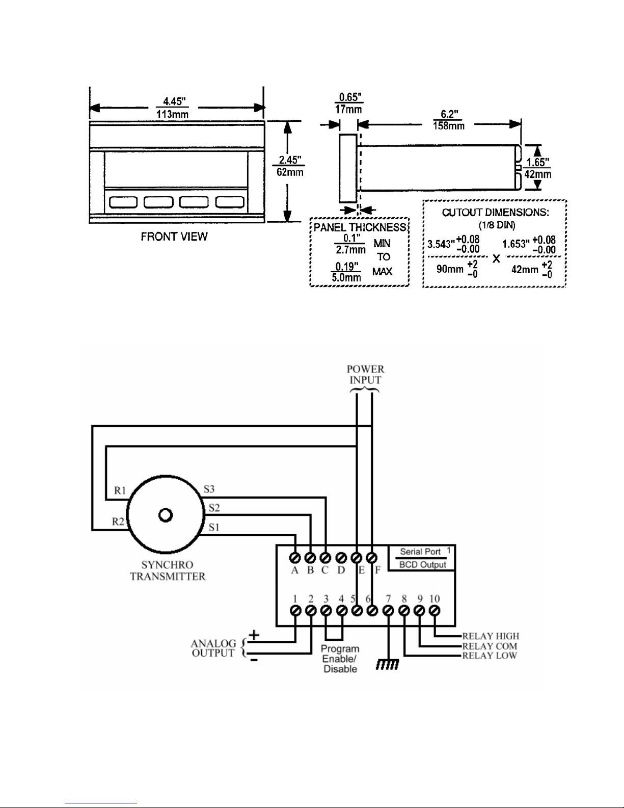
Figure 1.1 Mechanical Dimensions
Figure 1.2 Field Wiring Diagram
6
Page 7
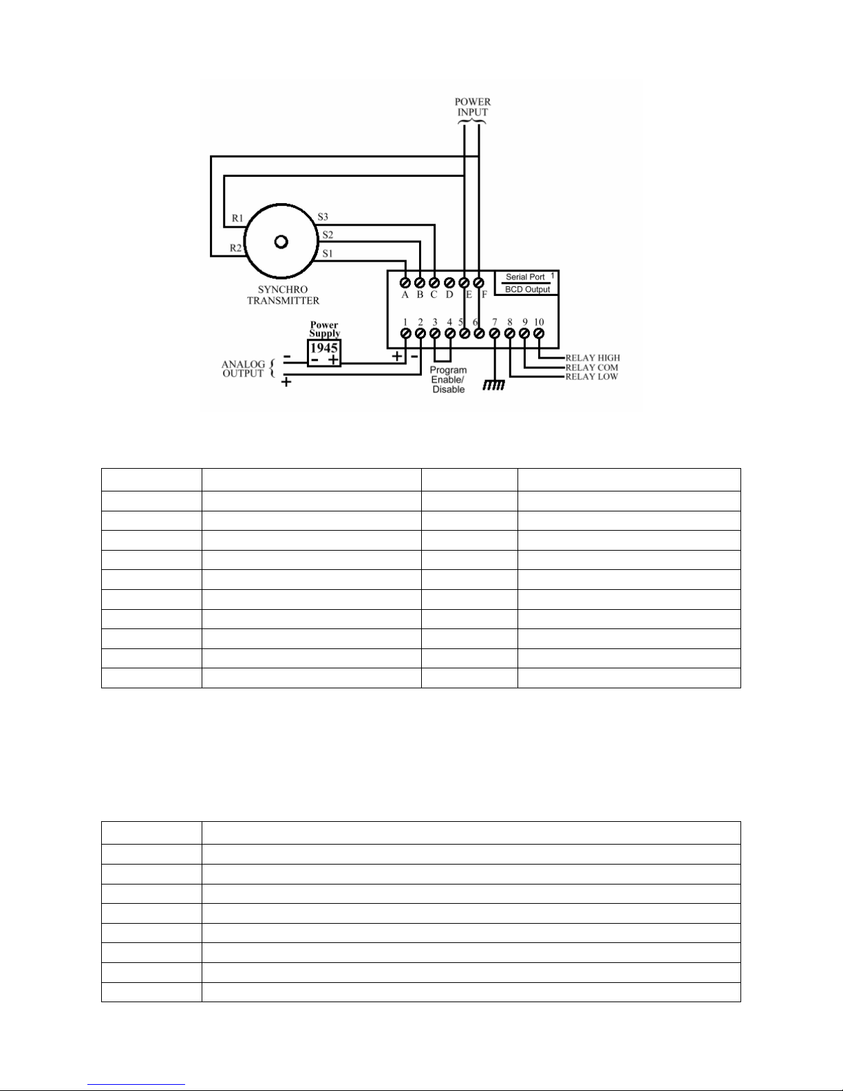
Figure 1.3 Field Wiring Diagram with 4-20mA Output
Table 1.1 Terminal Functions
Terminal Function Terminal Function
A S1 1 Analog Output +
B S2 2 Analog Output –
C S3 3 Program Mode Inhibit
D (Spare) 4 Inhibit Return
E R1 * 5 Line L1 *
F R2 * 6 Line L2 *
7 Chassis Ground
* Terminals E & F are 8 Relay Low Contact N.O.
jumpered to 5 & 6 9 Relay Common
respectively 10 Relay High Contact N.O.
A DIP switch tells the firmware which hardware options are installed, so their function
can be enabled. It is located on the top PCB, above the power transformer and is
accessible through a slot in the left side of the case, towards the rear of the instrument.
Table 1.2 DIP Switch Functions
Switch # Function
1 Serial Communications Option Enable
2 MODBUS Protocol Enable
3 Spare
4 High / Low Relay Limit Option Enable
5 Analog Output Option Enable
6 Spare
7 Spare
8 In-Factory Test & Calibration Menu Enable
7
Page 8

Installation Notes:
1) A resistor may be wired remotely across the analog output terminals to convert analog
output milliamp current to a voltage. Use Ohm’s Law to calculate the proper resistance
for the desired voltage based upon the 1250-LTC’s rated output current.
2) Maximum analog output load resistance: 0-1mA = 10K ohms; +/-1mA = 10K ohms;
0-2mA = 5K ohms; 4-20mA = 500 ohms.
3) Models with 4-20 mA analog output options must have an EXTERNAL LOOP POWER
SOURCE of 10.0 VDC minimum, 24.0 VDC maximum, in series with the current loop.
The INCON Model 1945 Power Supply is recommended for these installations,
(See Figure 1.3, page 7).
4) When additional remote indication is needed, several 1250-LTC’s may be wired in
parallel to the same transmitter. The 1250-LTC can also be connected via its serial port to
the INCON model RD-4 Remote Display unit.
5) The 1250-LTC and the synchro transmitter MUST BE WIRED TO THE SAME AC
SOURCE. Do not remove the jumpers from terminals E and F.
6) A wire jumper or keyswitch may be installed between terminals 3 & 4 to prevent the
program from being changed. When these terminals are jumpered the menu will read
“EP-x” instead of “OP-x”, which indicates that you can Examine each Parameter, but not
change them.
7) After installation and programming, install the rear terminal guard with screws provided.
8) For models with serial options, plug the cable onto the card edge with the red stripe
towards the outside of the case.
Application Bulletins:
1) If there is a large component of AC “ripple” present on the 1250 analog output, check the
isolation of all wiring with respect to earth ground. R1, R2, S1, S2, and S3 should
measure infinite resistance to earth ground. In applications where external isolation is not
sufficient, the Input Isolation Option (-I) is required to break the ground path that causes
this ripple. See Application Bulletin #000-1150 for more detailed information.
2) Analog outputs of 0-1mA, +/-1mA, and 0-2mA can be changed in the field to any one of
the other two (see Table 1.3). The configuration jumpers are located on the bottom PCB.
See Application Bulletin #000-1151 for more detailed information.
Table 1.3 Analog Output Configuration Jumpers
Output Signal: J8 J10 J12 J13
0-1mA Jumped Jumped Jumped
+/-1mA Jumped Jumped Jumped
0-2mA Jumped Jumped
8
Page 9

2.0 PROGRAMMING
The Model 1250-LTC has three methods of programming: numeric menu (traditional
1250); alphanumeric menu; and serial port programming commands. The 1250-LTC can be
ordered with either RS-232 or RS-485 serial port hardware. The serial programming
commands can be in the form of ASCII characters or MODBUS packets, depending upon the
position of DIP switch #2. See Tables 2.1, 2.2 & 2.3 for a full listing of all programming
menu items, commands, and syntax. See the simplified programming flowchart for tap
position on page 12, Figure 2.1.
2.1 Front Panel Programming
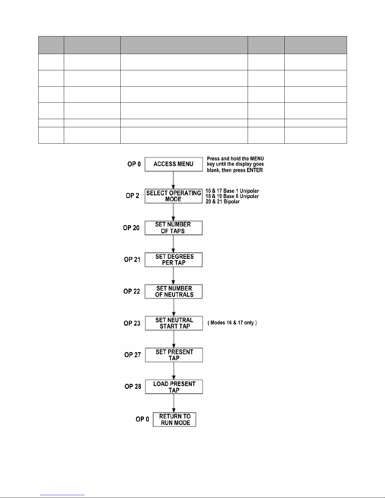
To access the numeric or alphanumeric programming menu, press the MENU key for
several seconds until the display goes blank, then press the SELECT/ENTER key. The
display should read “OP 0”. The default menu is the numeric menu. To choose the
alphanumeric menu, press the DOWN key to select OP 99. Press the SELECT/ENTER key,
the display should read “to OP”. Press the UP key. The display should read “run”. You are
now in the alphanumeric menu mode.
To change a parameter using the numeric or alphanumeric menus, select the parameter
to be changed from the menu, press the SELECT/ENTER key. The parameter’s present
setting will now be displayed. You can change the setting by pressing the UP or DOWN key.
To store the new setting, press the SELECT/ENTER key, the display will return to the menu.
Table 2.1 Numeric and Alphanumeric Menu Items:
Numeric
OP 0 run Press the SELECT/ENTER key to exit the
OP 2 Func Select Operating Mode (see pages 34-37) 21 16, 17, 18, 19, 20,
OP 3 tCrLY Selects which relay will assert
OP 4 tCrdL Sets the delay time before Tap Change
OP 5 tCrLt Sets duration of time the Tap Change
OP 6 dHF-L Selects which visit to the Draghand
OP 10 LtCLr Low Tap Alarm Clear CL
OP 11 HtCLr High Tap Alarm Clear CL
OP 15 rL Lt Sets low relay limit tap -16 Any valid tap
OP 16
OP 17 rL Ht Sets high relay limit tap +16 Any valid tap
OP 18
Alpha-numeric
Protocol
LtrLY
HtrLY
Function: Default
Value:
Program mode
OFF OFF, LO, HI
momentarily, after each tap change
0.0 0.0 to 9.9
Acknowledge Relay turns on (Seconds)
0.0 0.0 to 9.9
Acknowledge Relay stays on (Seconds)
LASt “FirSt”, “LASt”
positions (first
the day counters
Selects which relay will assert when the
“Low Tap” alarm limit is reached
Selects which relay will assert when the
“High Tap” alarm limit is reached
time or last time) will begin
OFF OFF, LO, HI
OFF OFF, LO, HI
Programmable
Range:
21
number
number
9
Page 10

Numeric
OP 19
OP 20
OP 21
OP 22 nEu Number of neutral taps 1 0 to 8
OP 23 n St Sets lowest neutral tap 0-1 Any valid tap
OP 27 S Pt Sets present tap position 0 Any valid tap
OP 28 L Pt Loads present tap position into memory Ld
OP 29 dSPrL Enables display of “r” or “L” in Function
OP 30 CAL E Enables analog output Calibration Mode OFF On or OFF
OP 31 L CAL Forces the analog output to its lowest
OP 32 H CAL Forces the analog output to its high scale
OP 33 d CAL Forces the analog output to its mid scale
OP 34 t CAL Forces the analog output to alternate
OP 39 dOG t Forces a Watchdog Reset (Factory use
OP 40 LED t Display LED Test: Turns on all LED’s -8.8.8.8.8.
OP 41 rS t RS-232 Echo Test: Re-transmits characters
OP 42 InCAL Calibrates synchro input circuitry CAL
OP 43 rLY t Relay Test: UP and DOWN keys toggle
OP 50 dSPbL Causes the display to go blank after 60 sec. OFF On or OFF
OP 51 SEr Serial Communication Mode:
OP 53 Aut25 Auto-Reset after “FA 25” Loss of Synchro
OP 54
OP 55 ttCLt Sets Total Tap Change counter alarm limit
OP 56 ttrLY Selects which relay will assert when the
OP 57 ttPrE Presets the Total Tap Change counter in
OP 58 ttdtE Total Tap Change counter reference date
OP 59 ttCdS Displays Total Tap Change Count and
Alpha-numeric
Protocol
dEGrE
tAPS
d SEG
25rLY
Function: Default
Value:
Displays absolute synchro position in
degrees with one decimal place resolution
Number of taps 33 2 to 40
Degrees per tap 10.000 -99999 to +99999
Modes 20 and 21
signal output
signal output
signal outputs
between high and low scale signal outputs
only)
received through the RS-232 serial port
between LO and HI relays
0=Serial Disabled,
1=Data Logger Mode, 2=Polled Mode,
3=Sampled Mode, 4=Serial Command
Mode, 5=Reserved, 6= MODBUS Mode,
7=Remote Display Driver Mode
Signal Error (page 50)
Selects which relay will assert when the
“FA 25” error is active
in THOUSANDS
Total Tap Change counter limit is reached
THOUSANDS
Enter day, month, year
reference date Press ENTER to exit
OFF On or OFF
LO
HI
- -
LO then HI
<<Press ENTER>>
rS
LO then HI
0 0 to 4, and 6
OFF On or OFF
OFF OFF, LO, HI
000.01 000.01 to 999.99
OFF OFF, LO, HI
000.00 000.00 to 999.99
01–01–00
Programmable
Range:
number
number
10
Page 11

Numeric
OP 60 Aut27 Auto-Reset after “FA 27” Unstable
OP 61
OP 62 OtGLt Sets On-Tap guard band limit (Degrees) 0.1 0.1 to 9999.9
OP 63 OtrLY Selects which relay will assert when the
OP 64 OtdtE On-Tap reference date
OP 65 OtdIS Scrolls through the list of taps, to select,
OP 66 Otdtd Scrolls through the list of taps which have
OP 67 OtCLr Clears the On-Tap alarm CL
OP 68 OtrSt Resets all On-Tap logs & alarm rESEt
OP 70 udCLt Sets the alarm limit for the number of
OP 71 udrLY Selects which relay will assert when the
OP 72 uddtE UP TO & DOWN TO Change counter
OP 73 uddIS Scrolls through the list of taps to select,
OP 74 udCLr Clears an active Up-To and Down-To
OP 75 udrSt Resets all Change Up-To and Down-To
OP 80 POrt Sets serial port parameters: (press the UP
OP 85 PtnLt Sets the limit for number of days without a
OP 86 PtrLY Selects which relay will assert when the
OP 87 PtdIS Displays the number of days since the last
Alpha-numeric
Protocol
27rLY
Function: Default
Value:
OFF On or OFF
Synchro Signal Error (page 50)
Selects which relay will assert when the
“FA 27” error is active
On-Tap guard band limit is reached
Enter day, month, year
Press ENTER to display the highest
measured deviation, for that tap
Press MENU to escape back to the menu
exceeded the On-Tap alarm limit to select,
Press ENTER to display the highest
measured deviation, for that tap
Press MENU to escape back to the menu
changes UP TO any tap in THOUSANDS
“UP TO” change alarm limit is reached
reference date Enter day, month, year
Press ENTER to display the Change UpTo count Press ENTER to display the
Change Down-To count, for that tap
Press MENU to escape back to the menu
Change alarm
counters and alarm
or Down key to select a value, press the
enter key to move to the next parameter)
Baud rate
Word length
Parity (n=none, E=even, O=odd)
Stop bits
Address (for RS-485 Multi-drop)
“Pass Thru Neutral”
“Pass Thru Neutral” time limit is reached
“Pass-Through-Neutral”
OFF OFF, LO, HI
OFF OFF, LO, HI
01–01–00
Any valid tap
Any valid tap
000.01 000.01 to 999.99
OFF OFF, LO, HI
01–01–00
0 Any valid tap
CL
rESEt
9600
8
n
1
128
OFF Off, 0.1 to 365.0
OFF OFF, LO, HI
Programmable
Range:
number
number
number
2400, 4800, 9600,
14400, 19200,
28800,38400,
57600, 76800
7 or 8
n, E, O
1 or 2
0 to 255
11
Page 12
Numeric
OP 88 PtrSt Resets the “Pass-Through-Neutral”
OP 90 1dCLt Sets the limit for number of consecutive
OP 91 1drLY Selects which relay will assert when the
OP 92 1ddIS Displays the number of days since the
OP 93 1dCLr Clears “One Direction Change” alarm CL
OP 99 tO OP Toggles between Numeric and
Alpha-numeric
Protocol
Function: Default
Value:
rESEt
counter & alarm
2 2 to 30
tap changes in One Direction
OFF OFF, LO, HI
“One Direction Change” limit is reached
“One Direction Alarm” was asserted
tO OP
Alphanumeric menus
Programmable
Range:
Figure 2.1 Simplified Programming Flowchart
12
Page 13

2.2 Serial Port Programming - ASCII:
These commands require either the RS-232 (-S) or RS-485 (-M) hardware option. To use
the serial port programming commands, connect a computer terminal to the serial port cable. The
terminal must have the proper Comm port settings to communicate to the 1250-LTC (see Sections
3.3 and 3.4, pages 46 - 47). See Table 2.2 for a full listing of all Serial Programming Commands
and syntax. At the command prompt, type a command followed by the new parameter setting,
using proper syntax as shown in Table 2.2. Typing the command only, without a new para-
meter setting, will cause the 1250-LTC to transmit the present setting for that parameter.
Table 2.2 Serial Programming ASCII Commands:
◊=space ª=enter
Command Syntax: Function: Explanation:
SETUPª Enter the Setup Mode This command must be entered before
any other commands can be made.
EXITª Re-starts the serial connection Changes to comm. port settings will take
effect
RUNª Return to the Run Mode Changes to settings will take effect
DISPª Displays all setup parameters Each setup parameter command is dis-
played with the current value following it
DUMPª Displays all measured LTC
information
(See Figure 2.2, page 17)
POSª Displays present Tap #, synchro
position (in degrees) and current
On-Tap deviation degrees
MODE◊nnª
ACKRLY◊LOª
ACKDLY◊nn.nª
ACKHOLD◊nn.nª
DHCOUNT◊FIRSTª
DHLRST Low Draghand Reset Draghand value becomes present tap
DHHRST High Draghand Reset Draghand value becomes present tap
LTLMT◊nnª
LTRLY◊LOª
LTCLRª Clears Low Tap Alarm Also resets “Days Since Alarm” counter
HTLMT◊nnª
HTRLY◊LOª
HTCLRª Clears High Tap Alarm Also resets “Days Since Alarm” counter
TAPS◊nnª
Segmented modes See Section 2.4, page 34-37 for details
Selects which relay will assert
momentarily after each tap
change
Sets the delay time, in seconds,
before the ACK relay asserts
Sets the duration, in seconds,
that the ACK relay remains on
Selects which visit to the
Draghand position to begins the
day counter
Set Low Tap alarm limit n= an integer, any valid tap number
Selects which relay is associated
with the Low Tap alarm
Set High Tap alarm limit n= an integer, any valid tap number
Selects which relay is associated
with the High Tap alarm
Set number of taps n= an integer from 2 to 40
Lists: Total tap change count, Days since
Pass-Through-Neutral, High & Low
Draghand positions, Change Up-To and
Down-To counts for each tap, Maximum
On-Tap deviations for each tap, etc…
Reads Tap #, 0.0 to 359.9 degrees, with
one decimal place of resolution
Press ª (enter) to exit
Choose “OFF”, “LO” or “HI” relay to
assert momentarily after each tap change
n= a number from 0.1 to 9.9 with one
decimal place resolution
n= a number from 0.1 to 9.9 with one
decimal place resolution
Choose “FIRST” or “LAST” visit.
The number of days since the LTC
visited that extreme position the first or
last time
Choose “OFF”, “LO” or “HI” relay to
assert when the alarm limit is reached
Choose “OFF”, “LO” or “HI” relay to
assert when the alarm limit is reached
13
Page 14

Command Syntax: Function: Explanation:
DEGSEG◊n.nnnnª
NEUTRALS◊nª
NSTART◊nnª
SETTAP◊nnª
LDTAPª
DISPRL◊ONª
ANACALª
WDOGTESTª
LEDTESTª Turns on all display segments Press the enter key to stop the LED test
INCALª Self-calibrates the input circuitry Outputs “Pass” or “Fail” calibration
RLYTESTª Forces Hi / Lo relay output to
DSPBL◊ONª
SERIAL◊nª
AUTO25◊ONª
FA25RLY◊LOª
RESET25ª Manually clears the “FA 25”
TTCLMT◊nnn.nnª
TTCRLY◊LOª
TTCPRE◊nnn.nnª
TTCDATE◊mm-dd-yyyyª
AUTO27◊ONª
FA27RLY◊LOª
RESET27ª Manually clears the “FA 27”
Set degrees per segment n= a floating point number, 5 digits max,
average number of degrees between taps
Set number of neutral taps n= an integer from 0 to 8
Set lowest neutral tap number n= an integer, any valid tap number
Set present tap position n= an integer, any valid tap number
Load present tap pos. into memory
Enables the display of “r” (raised)
and “L” (lowered) tap numbers
Must be done for SETTAP to take effect
“ON” or “OFF” When enabled causes
the display to show “r” and “L” in
function modes 20 and 21 only
Enter analog calibration mode, the
1250 analog output will be forced
to Low / Mid / High signal output
Forces a Watchdog Reset This command is for factory use only.
Press the space bar to toggle between
Low / Mid / High analog output. Press the
enter key to stop calibration
result
Press the Space Bar to toggle between
close
Enables the display blanking
feature
Lo or Hi relay Press ª (enter) to exit
“ON” or “OFF” When enabled causes
the display to go blank after 60 sec.
Set serial communication mode 0=Serial Disabled, 1=Data Logger
Mode, 2=Polled Mode,
3=Sampled Mode,
4=Serial Command Mode, 5= Reserved,
6=MODBUS Mode, 7=Remote Display
Driver
Enables automatic reset of the
“FA 25” Loss of Synchro Signal
Error (page 50)
Selects which relay is associated
with the “FA 25” Error
“ON” or “OFF” When “ON”, the
“FA 25” alarm will automatically reset
when the condition clears
Choose “OFF”, “LO” or “HI” relay to
assert when the FA 25 Error is active
When AUTO25 is “OFF”, manually
alarm
Sets the Total Tap Change count
alarm limit in THOUSANDS
Selects which relay is associated
with the Total Tap Change count
clears the alarm and opens the relay
n= a number from 0.00 to 999.99 with
two decimal place resolution
Choose “OFF”, “LO” or “HI” relay to
assert when the alarm limit is reached
alarm
Presets the Total Tap Change
counter
and clears the alarm
Sets the Total Tap Change
counter reference date
in THOUSANDS
Enables automatic reset of the
“FA 27” Unstable Synchro
Signal Error (page 50)
Selects which relay is associated
with the “FA 27” Error
n= a number from 0.00 to 999.99 with
two decimal place resolution
mm-dd-yyyy = Month <hyphen> Day
<hyphen>Year (4 digits)
“ON” or “OFF” When “ON”, the
“FA 27” alarm will automatically reset
when the condition clears
Choose “OFF”, “LO” or “HI” relay to
assert when the FA 27 Error is active
When AUTO27 is “OFF”, manually
alarm
clears the alarm and opens the relay
14
Page 15

Command Syntax: Function: Explanation:
OTGDLMT◊nn.nª
Sets the On-Tap guard band
limit in DEGREES
OTRLY◊LOª
Selects which relay is associated
with the On-Tap alarm
OTDVTNª Displays the tap with the greatest
On-Tap Deviation
OTDATE◊mm-dd-yyyyª
Sets the On-Tap reference date
OTCLRª Clears the On-Tap alarm Data is retained, the alarm is cleared
OTRSTª Resets all On-Tap logs & alarm All On-Tap data is erased, alarm cleared
UPDNLMT◊nnn.nnª
Sets the alarm limit for the
number of changes “Up-To”
and “Down-To” any tap
in THOUSANDS
UPDNRLY◊LOª
Selects which relay is associated
with the “Up-To / Down-To”
Change alarm
UPDNDATE◊mm-dd-yyyyª
Sets the Up To / Down To
Change counter reference date
UPDNCLRª Clears an active Up-To or
Down-To Change alarm
UPDNRSTª Resets all Change Up-To and
Down-To counters and alarm
PORT◊bbbb◊w◊p
◊s◊aª
Set comm. port settings: baud
rate, word length, parity, stop
bits, and address
SITEID◊Abcd-Xyz & 123ª
Identifies installation site on the
“DUMP” header
PTNLMT◊nnnª
Sets the alarm limit for the
number of DAYS without a
“Pass Through Neutral”
PTNRLY◊LOª
Selects which relay is associated
with the “Pass-Through-Neutral”
alarm
PTNRSTª Resets the “Pass-Through-
Neutral” counter & alarm
1DTCLMT◊nnª
Sets the alarm limit for the
number of consecutive tap
changes in One Direction
1DTCRLY◊LOª
Selects which relay is associated
with the “One Direction” alarm
1DTCCLRª Clears a “One Direction” alarm
MENU◊1ª
Set the keyboard button menu
type
n= a number of degrees from 0.0 to 99.9
with one tenth degree resolution
Choose “OFF”, “LO” or “HI” relay to
assert when the alarm limit is reached
Displays Tap Number and Deviation
mm-dd-
yyyy = Month <hyphen> Day
<hyphen>Year (4 digits)
n= a number from 0.00 to 999.99 with
two decimal place resolution
Choose “OFF”, “LO” or “HI” relay to
assert when the alarm limit is reached
mm-dd-yyyy = Month <hyphen> Day
<hyphen>Year (4 digits)
If a tap with an Up-To or Down-To Change
counter exceeding the programmed limit is
re-visited, the alarm will re-activate
All Up-To and Down-To counters are reset
to zero and an active alarm is turned off
b=
2400, 4800, 9600, 14400, 19200,
28800, 38400, 57600, 76800 baud
w= 7 or 8 bit word
p= n, E, O
s= 1 or 2 stop bits
a= 0 to 255
40 ASCII Characters – Upper / lower case
letters, numbers, punctuation marks
n= a number from 0.0 to 365.0 with one
decimal place resolution
Choose “OFF”, “LO” or “HI” relay to
assert when the alarm limit is reached
n= an integer from 2 to 30, OFF
Choose “OFF”, “LO” or “HI” relay to
assert when the alarm limit is reached
“1” = Numeric “OP” menu or
“2” = Alpha-numeric menu
15
Page 16

HELP◊(command) ª
Provides on-line help on the
specific command entered or
lists all available commands
An explanation of a command and the
proper entry syntax is given. If no
command is entered, all commands will
be listed with syntax but no explanations
To prevent accidental or unwanted changes to the program parameters, a jumper wire
may be installed across terminals 3 & 4. With this jumper installed, the numeric menu will
read “EP nn” instead of “OP nn”. All parameters can be viewed but no changes can be made.
16
Page 17

Site ID: Maplewood Sub LTC #2
INCON 1250-LTC Firmware Revision X.xx Copyright 2007
Present Tap: 5
Total Tap Changes: 5729
Low Draghand: -7 35.4 Days Since LAST
High Draghand: 8 17.6 Days Since LAST
ALARMS:
Since activated - Days: Limit: Ref Date:
On-Tap Deviation 0.65 3.0 08-30-2007
Instability -- --
Synchro Signal Lost -- - 1 Direction Change 0.86 04
Up Down Count -- 123456 08-30-2007
Total Tap Changes 0.66 1234567 08-30-2007
Low Tap -- -10
High Tap 0.86 12
Pass Through Neut 0.95 30.0
TAP STATISTICS:
Tap Max. Dev. Change Change
Num: Degrees: Up-To: Dn-To:
-16 + 0.0 0 0
-15 + 0.0 0 0
-14 + 0.0 0 0
-13 + 0.0 0 0
-12 - 0.4 0 1
-11 - 0.4 1 2
-10 - 0.3 2 3
-9 + 0.4 3 9
-8 + 0.5 9 85
-7 + 0.8 85 215
-6 + 0.9 215 608
-5 + 0.9 608 1935
-4 + 1.1 1935 5564
-3 + 1.2 5564 6258
-2 + 1.1 6258 7145
-1 + 1.3 7145 5199
0-1 + 0.0 5199 5199
0-2 - 1.3 5199 8064
0-3 + 0.0 8064 8064
1 + 1.4 8064 40792
2 + 2.2 40792 22186
3 + 1.9 22186 9420
4 + 1.4 9420 7384
5 + 1.2 7384 4008
6 + 0.9 4008 1523
7 + 0.7 1523 407
8 - 0.6 407 115
9 - 0.6 115 11
10 + 0.5 11 4
11 - 0.3 4 2
12 - 0.4 2 1
13 + 0.4 1 0
14 + 0.0 0 0
15 + 0.0 0 0
16 + 0.0 0 0
Visit
Visit
Figure 2.2 Serial Data Dump Example
17
Page 18

2.3 Serial Port Programming - MODBUS:
This type of serial communication require the RS-232 (-S) or RS-485 (-M) hardware option. To
communicate to the 1250-LTC with MODBUS protocol, connect a computer with the appropriate
MODBUS communication software and serial port hardware to the 1250-LTC’s serial port cable.
The computer must have the proper Comm port settings to communicate to the 1250-LTC (see
Section 3.3, page 46). See Table 2.3 for a full listing of all MODBUS Registers, the definition
and binary format for each.
In the following Table 2.3 the meanings of the columns is as follows:
Register: MODBUS register address as seen in a MODBUS command beginning with
register 40001 and ending with 45895. These addresses are in decimal.
Hex: The same register’s address in hexadecimal, this value is calculated by
subtracting 40001 from the register number. Thus register 40001 in decimal
becomes 0000 in hex, and 40257 in decimal becomes 0100 in hex.
Function: Defines what each register contains or does when written. Some registers
are read only and have no meaning when written. Others can be written
or read. Others are “write only” special functions and cause actions to be
performed when they are written.
Format: This column defines what a register contains bit-by-bit in binary. A row of 16
symbols shows what each of the 16 bits of the register contain MSB first
and LSB last. A BCD formatted floating point register is shown as
follows (two 16 bit binary words):
Bcdabcdbbcdcbcdd bcde000000vspppp
bcda, bcdb, bcdc, bcdd, bcde are each four-bit BCD digits, as it
would be seen on a display.
000000 are 6 unused bits that report as 0 when read and must be 0
when written.
v is an overflow bit that indicates that the number in the register is too
big to display when it is a 1. 0 indicates a valid register value.
is the sign bit and is 1 when the value in the register is negative. 0
s
indicates a positive number.
pppp
is the position of the decimal point within the bcd digits.
Most registers are not as complex as a floating-point register.
An alternate floating-point format is supported and selected by writing a 1 to
the 40256d (00ff h) register. This selects an IEEE floating-point format as
follows (two 16 bit binary words):
seeeeeeeemmmmmmm mmmmmmmmmmmmmmmm
The format of the IEEE floating-point number is as follows:
s is the sign bit,
is the exponent bits, and
e
m
are the mantissa bits.
18
Page 19

The MODBUS protocol is a master/slave packet based protocol with the 1250-LTC operating
as a RTU slave. The MODBUS function commands recognized by the 1250-LTC are “3”
(read multiple registers) and “16” (write multiple registers). By supporting these two
commands the 1250-LTC is in level 0 compliance. Using these two commands it is possible
to configure the 1250-LTC as well as monitor it for current position. MODBUS RTU
command and response packets are formatted as follows:
2.3.1 MODBUS Packet Format - Read
Reading from Holding Registers:
GAP = A gap in transmission of 3.5 character frames indicates to the slaves that a new packet
is to follow. No transmission gaps within a packet may exceed 1.5 character frames.
Byte 1 = Device Address: Address 0 is a broadcast address that all units respond to regardless
of programmed address. All other addresses can be programmed and used in this mode.
Byte 2 = Function Code: When reading holding registers, this byte is “03h”
Data Block = Begins with the number of the first register (two bytes) in a command packet,
or data from the first register (two bytes) in a response packet. Followed by the number of
registers to be read (two bytes) in a command packet, or by data from subsequent registers.
Last 2 Bytes = Error Checking CRC – Lo Byte & Hi Byte
Table 2.3 Read Registers Command Format
GAP
3.5
Char
Min. 80h 03h 01h 03h 00h 04h xx xx
Device
Address
Function
Code
# of First
Register
Hi
# of First
Register
Lo
# of
Registers to
Read Hi
# of
Registers to
Read Lo
CRC
Lo
CRC
Hi
Table 2.4 Read Registers Response Format
GAP
3.5
Char
Min. 80h 03h 08h 01h 03h 00h 03h
Device
Address
Function
Code
Byte
Count
Data from
First Register
Hi
Data from
First Register
Lo
Data from
Second
Register
Hi
Data from
Second
Register
Lo
…… …… Data from Last
Register Hi
Data from Last
Register Lo
CRC
Lo
CRC
Hi
…… …… 00h 02h xx xx
19
Page 20

2.3.2 MODBUS Packet Format - Write
Write to Holding Registers:
GAP = A gap in transmission of 3.5 character frames indicates to the slaves that a new packet
is to follow. No transmission gaps within a packet may exceed 1.5 character frames.
Byte 1 = Device Address: Address 0 is a broadcast address that all units respond to regardless
of programmed address. All other addresses can be programmed and used in this mode.
Byte 2 = Function Code: When writing to holding registers, this byte is “10h”
Data Block = Begins with the number of the first register to be written (two bytes), followed
by the number of registers to be written (two bytes), in either command or response packets.
In a command packet the programming data for the first register will be the next two bytes
followed by programming data for subsequent registers.
Last 2 Bytes = Error Checking CRC – Lo Byte & Hi Byte
Table 2.5 Write Registers Command Format
GAP
3.5
Char
Min. 80h 10h 10h 00h 00h 04h
Device
Address
Function
Code
# of First
Register to be
written to Hi
# of First
Register to be
written to Lo
# of Registers
to Write Hi
# of Registers
to Write Lo
Byte
Count
Program Data for
First Register
Hi
Program Data for
First Register
Lo
Program Data for
Second Register
Hi
Program Data for
Second Register
Lo
08h 00h 01h 03h 60h
……
……
Program Data for
Last Register Hi
Program Data for
Last Register Lo
CRC
Lo
CRC
Hi
…… …… 00 01 xx xx
Table 2.6 Write Registers Response Format
GAP
3.5
Char
Min. 80h 10h 01h 00h 00h 04h xx xx
Device
Address
Function
Code
# of First
Register to
be written to
Hi
# of First
Register to
be written to
Lo
# of
Registers
to Write
Hi
# of
Registers
to Write
Lo
CRC
Lo
CRC
Hi
20
Page 21

2.3.3 MODBUS Packet Format – Error Exception Response
When the master sends a command, the MSB bit in the Function Code is always clear. When
a slave responds to the command, the slave leaves the MSB bit in the Function Code clear if
the response is a normal response and sets MSB bit on if the response is an error exception
response.
GAP = A gap in transmission of 3.5 character frames indicates to the slaves that a new packet
is to follow.
Byte 1 = Device Address: Address 0 is a broadcast address that all units respond to regardless
of programmed address. All other addresses can be programmed and used in this mode.
Byte 2 = Function Code: This byte will be the last command sent plus the MSB set on.
Exception Code = Illegal Command = 01
Illegal Register = 02
Last 2 Bytes = Error Checking CRC – Lo Byte & Hi Byte
Table 2.7 Error Exception Response Format
GAP
3.5
Char
Min. 80h 90h 02 xx xx
Device
Address
Function
Code
Exception
Code
CRC
Lo
CRC
Hi
21
Page 22

Table 2.8 RS-485 MODBUS Register Definitions
Register
Class & Type Function: Binary Format:
Address:
Decimal
[hex]
40001
[0000]
40002
[0001]
Class:
Configuration
Type:
Read\write
Class:
AlarmClearing,
AlarmStatus
Type:
Setup / run
mode select
Synchro input
signal status
Read\write,
Write 0 to clear
40257,
40258
[0100,
0101]
Class: State
Type: Read-only
Angle
(cumulative)
[The value can
exceed +\- 360.0
degrees]
40264
[0107]
40513
[0200]
Class: State
Type: Read-only
Class:
Configuration
Type: Write-only,
Tap, neutral
Draghand reset
control
Write one to clear
40516
[0203]
Class: State
Type: Read-only
High tap
draghand
000000000000000s
LSB (s)
0 – run mode
1 – setup mode
This bit must be 1 before any
program parameter can be changed
000000000000000s
LSB (s)
0 – OK input signal is present
1 – ALARM input signal is lost
seeeeeeeemmmmmmm MSW
mmmmmmmmmmmm LSW
IEEE 754-1985 single precision float
MSW = [0100] LSW = [0101]
tttttttt0000nnnn
[“0000” are unused bits]
“t”= 8-bit tap number
“n”= 4-bit neutral number
(both in binary)
00000000000000HL
“H”= high draghand
“L”= low draghand
0 ignored
1 = reset
tttttttt0000nnnn
[“0000” are unused bits]
”= 8-bit tap number
“t
“n
”= 4-bit neutral number
(both in binary)
22
Page 23

Register
Class & Type Function: Binary Format:
Address:
Decimal
[hex]
40519
[0206]
Class: State
Type: Read-only
Low tap
draghand
tttttttt0000nnnn
[“0000” are unused bits]
“t
”= 8-bit tap number
“n”= 4-bit neutral number
(both in binary)
40520
[0207]
Class:
Configuration
Type: Read\write
Draghand
counter start
visit
000000000000000s
LSB (s)
0 – First
1 – Last
Selects whether time since first or last
draghand visit to a tap is reported.
40769
[0300]
Class: State
Type: Read-only
Internal relay
states
00000000000000HL
“H”= high relay
“L”= low relay
If relay is on, bit = 1, else bit = 0
40777,
40778
[0308,
0309]
Class: State
Type: Read\write
Total tap change
count
ssssssssssssssss MSW
ssssssssssssssss LSW
MSW = [0308] LSW = [0309]
[NOTE: Always write both the high
(MSW) and low (LSW) words with
consecutive writes; do not write any
other register address between these two
writes.]
40785
[0310]
Class: State
Type: Read-only
Tap, neutral
with greatest
on-tap deviation
tttttttt0000nnnn
[“0000” are unused bits]
”= 8-bit tap number
“t
“n
”= 4-bit neutral number
(both in binary)
40786,
40787
[0311,
0312]
Class: State
Type: Read-only
Max measured
on-tap deviation
seeeeeeeemmmmmmm MSW
mmmmmmmmmmmm LSW
IEEE 754-1985 single precision float
MSW = [0311] LSW = [0312]
23
Page 24

Register
Address:
Decimal
[hex]
40801
[0320]
40802
[0321]
40803
[0322]
40804
[0323]
40805
[0324]
40806
[0325]
Class & Type Function: Binary Format:
Class:
AlarmClearing,
AlarmStatus
Type:
On-tap alarm
state
000000000000000s
LSB (s
)
0 – OK
1 – ALARM
Read\write,
Write 0 to clear
Class:
AlarmClearing,
AlarmStatus
Type:
Read\write,
One-direction
alarm state
000000000000000s
LSB (s)
0 – OK
1 – ALARM
Write 0 to clear
Class:
AlarmClearing,
AlarmStatus
Type:
Instability alarm
state
000000000000000s
LSB (s)
0 – OK
1 – ALARM
Read\write,
Write 0 to clear
Class:
AlarmClearing,
AlarmStatus
Type
Loss-of-signal
alarm state
000000000000000s
LSB (s)
0 – OK
1 – ALARM
Read\write,
Write 0 to clear
Class:
AlarmClearing,
AlarmStatus
Type:
Change up-to
\ down-to alarm
state
000000000000000s
LSB (s)
0 – OK
1 – ALARM
Read\write,
Write 0 to clear
Class:
AlarmClearing,
AlarmStatus
Pass-throughneutral alarm
state
000000000000000s
LSB (s)
0 – OK
1 – ALARM
Type:
Read\write,
Write 0 to clear
24
Page 25

Register
Address:
Decimal
[hex]
40807
[0326]
40808
[0327]
40809
[0328]
40833
[0340]
40834
[0341]
40835
[0342]
40836
[0343]
40837
[0344]
40838
[0345]
Class & Type Function: Binary Format:
Class:
AlarmClearing,
AlarmStatus
Type:
Total tap change
alarm state
000000000000000s
LSB (s
)
0 – OK
1 – ALARM
Read\write,
Write 0 to clear
Class:
AlarmClearing,
AlarmStatus
Type:
Low tap alarm
state
000000000000000s
LSB (s)
0 – OK
1 – ALARM
Read\write,
Write 0 to clear
Class:
AlarmClearing,
AlarmStatus
Type
High tap alarm
state
000000000000000s
LSB (s)
0 – OK
1 – ALARM
Read\write,
Write 0 to clear
Class: AlarmStatus
Type: Read-only
Class: AlarmStatus
Type: Read-only
Class: AlarmStatus
Type: Read-only
Days since
asserting On-tap
alarm
Days since
asserting Onedirection alarm
Days since
asserting
Instability
dddddddddddddddd
“d” = 10ths of a day
dddddddddddddddd
“d” = 10ths of a day
dddddddddddddddd
“d” = 10ths of a day
Alarm
Class: AlarmStatus
Type: Read-only
Days since
asserting
Loss-of –Signal
dddddddddddddddd
“d” = 10ths of a day
Alarm
Class: AlarmStatus
Type: Read-only
Days since
asserting Upto\down-to
dddddddddddddddd
“d” = 10ths of a day
alarm
Class: AlarmStatus
Type: Read-only
Days since last
Pass–throughneutral
dddddddddddddddd
“d” = 10ths of a day
25
Page 26

Register
Address:
Decimal
[hex]
40839
[0346]
40840
[0347]
40841
[0348]
40842
[0349]
40843
[034A]
40865
[0360]
40869
[0364]
40870
[0365]
41025
[0400]
Class & Type Function: Binary Format:
Class: AlarmStatus
Type: Read-only
Days since
asserting Total
tap changes
dddddddddddddddd
“d” = 10ths of a day
alarm
Class: AlarmStatus
Type: Read-only
Class: AlarmStatus
Type: Read-only
Class: AlarmStatus
Type: Read-only
Class: AlarmStatus
Type: Read-only
Class:
AlarmClearing,
StatisticsResetting
Type:
Write-only,
Days since
asserting Low
tap alarm
Days since
asserting High
tap alarm
Days since Low
draghand hit
new extremum
Days since High
draghand hit
new extremum
dddddddddddddddd
“d” = 10ths of a day
dddddddddddddddd
“d” = 10ths of a day
dddddddddddddddd
“d” = 10ths of a day
dddddddddddddddd
“d” = 10ths of a day
On-tap reset 000000000000000s
LSB (s)
0 = reset
1 = ignored
Write 0 to clear
Class:
AlarmClearing,
StatisticsResetting
Type:
Up-to/down-to
reset
000000000000000s
LSB (s)
0 = reset
1 = ignored
Write-only,
Write 0 to clear
Class:
AlarmClearing,
StatisticsResetting
Type:
Pass-throughneutral reset
000000000000000s
LSB (s
)
0 = reset
1 = ignored
Write-only,
Write 0 to clear
Class: state
Type:
Analog output 0000aaaaaaaaaaaa
12-bit number (in binary)
Read-only
26
Page 27

Register
Address:
Decimal
[hex]
44097
[1000]
44353
[1100]
44354,
44355
[1101,
1102 ]
44356
[1103]
44357
[1104]
44358
[1105]
44867
[1302]
44868
[1303]
Class & Type Function: Binary Format:
Class:
Configuration
Type:
Operating mode
00000000000mmmmm
LSBs (mmmmm
)
(see list of modes on page 34)
Read\write
Class:
Configuration
Number of taps 000000000nnnnnnn
7-bit number (in binary)
Type:
Read\write
Class:
Configuration
Type:
Read\write
Degrees per
segment
seeeeeeeemmmmmmm MSW
mmmmmmmmmmmm LSW
IEEE 754-1985 single precision float
MSW = [1101] LSW = [1102]
Class:
Configuration
Type:
Read\write
Class:
Configuration
Type:
Read\write
Class:
Configuration
Type:
Read\write
Class:
Configuration
Number of
neutrals
Neutral start
segment
Display
“r”&“L”
Preset tap
000000000000nnnn
LSBs (nnnn)
Up to 8 neutrals, in binary.
If field value > 8, clamps to 8
ssssssssssssssss
16 bits, first neutral tap
000000000000000d
LSB(d
)
0 = disabled
1 = enabled
ssssssssssssssss
16 bits, preset tap no.
Type:
Read\write
Class:
Configuration
Type:
Write-only
Load/clear
preset control
00000000000000cc
LSBs (cc)
00 – no operation
01 – clear offset
10 – load preset
27
Page 28

Register
Address:
Decimal
[hex]
45121
[1400]
45122
[1401]
45155
[1422]
45156
[1423]
45633
[1600]
45634
[1601]
Class & Type Function: Binary Format:
Class:
Configuration
Type:
Read\write
Class:
Configuration
Type:
Read\write
Class:
Configuration,
AlarmClearing
Type:
Display blank 000000000000000b
LSB(b)
0 = disabled
1 = enabled [display will blank]
Menu mode 000000000000000m
LSB (m)
0= numeric
1=alphanumeric
Auto reset 27 0000000 e
LSB (e
)
0 = disabled
1 = enabled
Read\write
Class:
Configuration,
AlarmClearing
Type:
Auto reset 25 0000000 e
LSB (e)
0 = disabled
1 = enabled
Read\write
Class:
Configuration
Type:
Read\write
RS-232 mode 0000000000000rrr
LSBs (rrr)
000 = Serial disabled
001 = datalogger mode
010 = polled mode
011 = sampled mode
100 = command
101 = reserved N/A
110 = RS485 Modbus
111 = remote display driver
Class:
Configuration
Type:
Read\write
Baud 000000000000bbbb
LSBs (bbbb)
0000 = 300 0001 = 1200
0010 = 2400 0011 = 4800
0100 = 9600 0101 = 14400
0110 = 19200 0111 = 28800
1000 = 38400 1001 = 57600
1010 = 76800
28
Page 29

Register
Address:
Decimal
[hex]
45635
[1602]
45636
[1603]
45637
[1604]
45638
[1605]
45889,
45890
[1700,
1701]
45891
[1702]
45892
[1703]
45893
[1704]
Class & Type Function: Binary Format:
Class:
Configuration
Type:
Read\write
Class:
Configuration
Type:
Read\write
Word length 000000000000000w
LSB (w
)
0 = 7 bits
1 = 8 bits
Parity 00000000000000pp
LSBs (pp)
00 = none
01 = even
10 = odd
Class:
Configuration
Type:
Read\write
Class:
Configuration
Type:
Stop bits 000000000000000s
LSB (s)
0 = 1 bits
1 = 2 bits
Address 00000000aaaaaaaa
LSBs (aaaaaaaa)
8-bit serial multidrop address
Read\write
Class:
Configuration
Type:
Read\write
Total tap change
counter limit
seeeeeeeemmmmmmm MSW
mmmmmmmmmmmm LSW
IEEE 754-1985 single precision float
MSW = [1700] LSW = [1701]
(in thousands of counts)
Class:
Configuration
Type:
Read\write
Total tap change
count alarm
relay
00000000000000 rr
LSBs (rr)
00 – OFF
01 – LO Relay
10 – HI Relay
Class:
Configuration
Type:
Reference year
for Total tap
change counter
0000yyyyyyyyyyyy
“y” = Year
(in binary)
Read\write
Class:
Configuration
Type:
Read\write
Reference date
for Total tap
change counter
0000mmmm 000ddddd
“m” = Month (January = 1)
“d” = Day (1-31)
(in binary)
29
Page 30

Register
Address:
Decimal
[hex]
46145
[1800]
46146
[1801]
46147
[1802]
46148
[1803]
46401,
46402
[1900,
1901]
46403
[1902]
46404
[1903]
46405
[1904]
Class & Type Function: Binary Format:
Class:
Configuration
Type:
On-tap guard
band limit
dddddddddddddddd
“d” = tenths of a degree
(in binary)
Read\write
Class:
Configuration
Type:
Read\write
On-tap alarm
relay
00000000000000 rr
LSBs (rr)
00 – OFF
01 – LO Relay
10 – HI Relay
Class:
Configuration
Type:
Reference year
for On-tap
counter
0000yyyyyyyyyyyy
“y” = Year
(in binary)
Read\write
Class:
Configuration
Type:
Read\write
Class:
Configuration
Type:
Read\write
Reference date
for On-tap
counter
Change up-to /
down-to counter
limit
0000mmmm 000ddddd
“m” = Month
“d” = Day
(in binary)
seeeeeeeemmmmmmm MSW
mmmmmmmmmmmm LSW
IEEE 754-1985 single precision float
MSW = [1900] LSW = [1901]
(in thousands of counts)
Class:
Configuration
Type:
Read\write
Change up-to /
down-to counter
alarm relay
00000000000000 rr
LSBs (rr)
00 – OFF
01 – LO Relay
10 – HI Relay
Class:
Configuration
Type:
Reference year
for up-to /
down-to counter
0000yyyyyyyyyyyy
“y” = Year
(in binary)
Read\write
Class:
Configuration
Type:
Read\write
Reference date
for up-to /
down-to counter
0000mmmm 000ddddd
“m” = Month
“d” = Day
(in binary)
30
Page 31

Register
Address:
Decimal
[hex]
46657
[1A00]
46658
[1A01]
46913
[1B00]
46914
[1B01]
47169
[1C00]
47170
[1C01]
47425
[1D00]
47426
[1D01]
Class & Type Function: Binary Format:
Class:
Configuration
Type:
Pass-throughneutral limit
dddddddddddddddd
“d” = tenths of a day
(in binary)
Read\write
Class:
Configuration
Type:
Read\write
Pass-throughneutral counter
alarm relay
00000000000000 rr
LSBs (rr)
00 – OFF
01 – LO Relay
10 – HI Relay
Class:
Configuration
Type:
One-direction
counter limit
0000000000ssssss
LSBs(ssssss)
6-bits, number of taps
Read\write
Class:
Configuration
Type:
Read\write
One-direction
counter alarm
relay
00000000000000 rr
LSBs (rr)
00 – OFF
01 – LO Relay
10 – HI Relay
Class:
Configuration
Low tap relay
limit
ssssssssssssssss
16-bit signed word, low tap limit
Type:
Read\write
Class:
Configuration
Type:
Read\write
Low tap alarm
relay
00000000000000 rr
LSBs (rr)
00 – OFF
01 – LO Relay
10 – HI Relay
Class:
Configuration
High tap relay
limit
ssssssssssssssss
16-bit signed word, high tap limit
Type:
Read\write
Class:
Configuration
Type:
Read\write
High tap alarm
relay
00000000000000 rr
LSBs (rr
)
00 – OFF
01 – LO Relay
10 – HI Relay
31
Page 32

Register
Address:
Decimal
[hex]
47938
[1F01]
47939
[1F02]
47940
[1F03]
48193
[2000]
48194
[2001]
48705
[2200]
Class & Type Function: Binary Format:
Class:
Configuration
Type:
Read\write
Tap change
acknowledge
relay
00000000000000 rr
LSBs (rr
)
00 – OFF
01 – LO Relay
10 – HI Relay
Class:
Configuration
Acknowledge
relay delay time
000000000sssssss
“s” = Delay in tenths of a second
Type:
Read\write
Class:
configuration
Acknowledge
relay duration
time
000000000sssssss
“s” = Duration in tenths of a second
Type:
Read\write
Class:
Configuration
Type:
Read\write
“FA 25” error
relay
00000000000000 rr
LSBs (rr)
00 – OFF
01 – LO Relay
10 – HI Relay
Class:
Configuration
Type:
Read\write
“FA 27” error
relay
00000000000000 rr
LSBs (rr)
00 – OFF
01 – LO Relay
10 – HI Relay
Class: State
Type:
Read\write
Tap index select
00000000 uuuuuuuu
Unsigned byte Zero-based index of tap
( value <= 39 decimal)
** NOTE: ALWAYS initially write the
tap index select register before reading
any of the tap attribute registers 0x3001
through 0x3007; that single write will
suffice until it’s desired to select a
different tap index, at which time another
write of the new tap index to this register
is required. Also write this register if a
restart may have occurred since the last
write; i.e. the value of tap index select is
not retained over a reset.
32
Page 33

Register
Address:
Decimal
[hex]
48706
[2201]
48707
[2202]
48708
[2203]
48709,
48710
[2204,
2205]
48711,
48712
[2206,
2207]
Class & Type Function: Binary Format:
Class: State
Type: Read-only
Tap number
corresponding
to Tap index
ssssssssssssssss
Signed 16-bit word
select
Class: State
Type: Read-only
Neutral number
corrresponding
to Tap index
uuuuuuuuuuuuuuu
Unsigned 16-bit word
select
Class: State
Type: Read-only
Class: State
Type: Read-only
Max On-Tap
deviation
corresponding
to Tap index
select
Upper and lower
words of Up-to
count
corresponding
to Tap index
select
ssssssssssssssss
Signed 16-bit word denoting tenths of a
degree
uuuuuuuuuuuuuuuu MSW
uuuuuuuuuuuuuuuu LSW
Unsigned 32-bit longword denoting upto count.
MSW = [3004] (upper)
LSW = [3005] (lower)
** NOTE: To obtain a consistent 32-bit
value, ALWAYS read 0x3004 BEFORE
0x3005; DO NOT read or write any
other register address between these
reads.
Class: state
Type: Read-only
Upper and lower
words of
Down-to count
corresponding
to
Tap index select
uuuuuuuuuuuuuuuu MSW
uuuuuuuuuuuuuuuu LSW
Unsigned 32-bit longword denoting
down-to count
MSW = [3006] (upper)
LSW = [3007] (lower)
** NOTE: To obtain a consistent 32-bit
value, ALWAYS read 0x3006 BEFORE
0x3007; DO NOT read or write any
other register address between these
reads.
33
Page 34

2.4 Operating Modes:
The model 1250-LTC has six operating modes. Each mode causes the 1250-LTC to
function differently. Determine which of the following operating modes is best suited to your
application. The proper mode will depend upon the desired numbering of the taps and where
the neutral taps are located:
16 = Base 1 Uni-polar Segmented Linear Analog (Neutrals can be at any tap number)
17 = Base 1 Uni-polar Segmented Stepped Analog (Neutrals can be at any tap number)
18 = Base 0 Uni-polar Segmented Linear Analog (Neutrals always at “0”)
19 = Base 0 Uni-polar Segmented Stepped Analog (Neutrals always at “0”)
20 = Bi-polar Segmented Linear Analog (Neutrals always at “0”)
21 = Bi-polar Segmented Stepped Analog (Neutrals always at “0”)
34
Page 35

Modes 16 & 17: Base 1 Uni-polar Segmented
These modes are used for LTC monitoring when the lowest tap number is 1. There
may be multiple neutral taps. They can be located anywhere between the lowest and highest
taps as long as they are grouped together in one section. Mode 16 has a linear analog output
that continuously varies with LTC shaft position. Mode 17 has a stepped analog output that
jumps with each tap change. To select this operating mode use the OP 2, Func, MODE
command to change the value to “16” or “17”.
Figure 2.3 Base 1 Uni-polar Mode Analog Output
Programming Example:
A typical transformer Load Tap Changer application with taps numbered 1 to 32,
o
2 neutral taps (17-1 and 17-2), with 9.5
per tap, presently set on tap “18” would be
programmed as follows:
OP 2 Operating mode = 17
OP 20 Number of taps = 33
OP 21 Degrees per tap = 9.5000
OP 22 Number of neutrals = 2
OP 23 Lowest neutral tap = 17
OP 27 Present tap = 18
OP 28 Load present tap
35
Page 36

Modes 18 & 19: Base 0 Uni-polar Segmented These modes are used for LTC monitoring
when the lowest tap number is 0. There may be multiple neutral taps, but they can only be
located at tap 0. Mode 18 has a linear analog output that continuously varies with LTC shaft
position. Mode 19 has a stepped analog output that jumps with each tap change. To select
this operating mode use the OP 2, Func, MODE command to change the value to “18” or
“19”.
Figure 2.4 Base 0 Uni-polar Mode Analog Output
Programming Example:
A typical transformer Load Tap Changer application with taps numbered 0 to 16,
2 neutral taps, with 10.5o per tap, presently set on tap “9” would be programmed as follows:
OP 2 Operating mode = 19
OP 20 Number of taps = 18
OP 21 Degrees per tap = 10.500
OP 22 Number of neutrals = 2
OP 27 Present tap = 9
OP 28 Load present tap
36
Page 37

Modes 20 & 21: Bi-polar Segmented These modes are used for LTC monitoring when the
neutral tap(s) are in the center of the dial and there is an equal number of raised and lowered
taps. There may be multiple neutral taps, but they can only be located at tap 0. Mode 20 has
a linear analog output that continuously varies with LTC shaft position. Mode 21 has a
stepped analog output that jumps with each tap change. To select this operating mode use the
OP 2, Func, MODE command to change the value to “20” or “21”.
Figure 2.5 Bi-polar Mode Analog Output
Programming Example:
A typical transformer Load Tap Changer application with 16 raised and 16 lowered
o
taps, 3 neutral taps, with 10
per tap, presently set on tap “2L” would be programmed as
follows:
OP 2 Operating mode = 21
OP 20 Number of taps = 35
OP 21 Degrees per tap = 10.000
OP 22 Number of neutrals = 3
OP 27 Present tap = -2
OP 28 Load present tap
37
Page 38

2.5 Programming Notes:
If the Degrees Per Tap value is not known, the 1250-LTC can be used to determine
this value. Follow these steps to determine the Degrees Per Tap value:
1) Enter the Programming Menu and select OP 19 (Degrees Mode) and press the ENTER
key.
3) The 1250-LTC should read a number from 0.0 to 359.9 with 1 decimal place.
4) Move the LTC to as many taps as possible. Record each tap number and the
corresponding degree reading displayed on the 1250-LTC in the table below.
5) Subtract one degree reading from the next, for each tap, and write it in the “Difference”
column in the table.
6) The differences should all be approximately the same. Take an average of the numbers in
the Difference column. The result is the Degrees Per Tap number that the 1250-LTC
needs for the OP 21, D SEG, or DEGSEG command.
7) Press the ENTER key to return to the Programming Menu.
Tap Number Degrees Difference Tap Number Degrees Difference
There is no programming required for the Analog Output. It automatically spans the full
range of taps, lowest tap to low output, highest tap to high output.
Programming for the High/Low Relays option is covered in Section 3.2, page 40.
Programming for the Serial ASCII Communication option is covered in Section 2.2, page 13.
Programming for the Serial MODBUS Communication option is covered in Section 2.3, page
18.
38
Page 39

3.0 OPTIONS
The standard Model 1250-LTC is configured with three options – Analog Output,
Hi/Lo Relays, and a Serial Port (RS-232 or RS-485). One more option is available – Input
Isolation. This section describes general use of each option, including wiring and
programming for each option.
3.1 Analog Output Option “-0”, “-1”, “-2”, “-4”
The analog output on the 1250-LTC may be used to feed position information to an
LTC Controller, a remote monitoring system such as SCADA, RTU or a remote indicator
such as the INCON model 1511-Z. In the all modes, the analog output automatically spans
between the highest and lowest taps.
Wiring:
The 4-20mA analog output option must be wired with an external power supply of
15.0 to 24.0 volts DC in series with the analog output current loop. (See Figure 1.3, page 7)
The INCON Model 1945 is available for this purpose. All other analog output options are
self-powered. Refer to Table 3.1 below for analog output load limits.
Table 3.1 Analog Output Load Limits
Analog Output: Load Minimum Load Maximum
0 to 1 mA Zero Ohms 10K Ohms
+/- 1 mA Zero Ohms 10K Ohms
0 to 2 mA Zero Ohms 5K Ohms
4-20 mA Zero Ohms 500 Ohms
Note:
If the presence of high voltage AC “ripple” is found on the analog output terminals, it
is generally not a problem with the 1250-LTC itself. Check the isolation of all field wiring
with respect to earth ground. All wiring should be completely isolated from ground. See
Section 3.5, page 48 Input Isolation Option. Contact INCON Technical Service for assistance
if the problem persists.
39
Page 40
3.2 High / Low Relay Limits Option “-R”
In the 1250-LTC, the High / Low Relays serve as alarm annunciators for the many
programmable limits associated with expanded LTC monitoring. The (two) relays are
normally open, dry contacts. Each relay may have one or more of the alarm limits assigned to
it. They may be used as feedback in a control system or as an alarm when the parameter has
reached its desired limits.
When the Tap Change Acknowledgement is not used, it is recommended that the
desired alarms be divided into two groups: Warning (LO) and Danger (HI). Less important
parameters should cause one relay (Warning) to turn on and more important parameters
should cause the other relay (Danger) to turn on. This way, the level of seriousness of an
alarm could be communicated, when remotely monitored. When the Tap Change
Acknowledgement is assigned to one relay (HI or LO), all other desired alarms must be
assigned to the other relay (LO or HI).
When the LO relay is asserted, the LED above the DOWN button, below the digital
display, will flash. When the HI relay is asserted, the LED above the UP button, below the
digital display, will flash. Note that the LED’s will flash even if the “-R” Relay Option is
not installed. This will alert an operator that an alarm limit has been reached, even on
an instrument without Relays. In addition to flashing the HI & LO Relay LED’s, an alarm
code(s) will be momentarily displayed, every 10 seconds, to explain which specific alarm(s) is
causing the alarm condition.
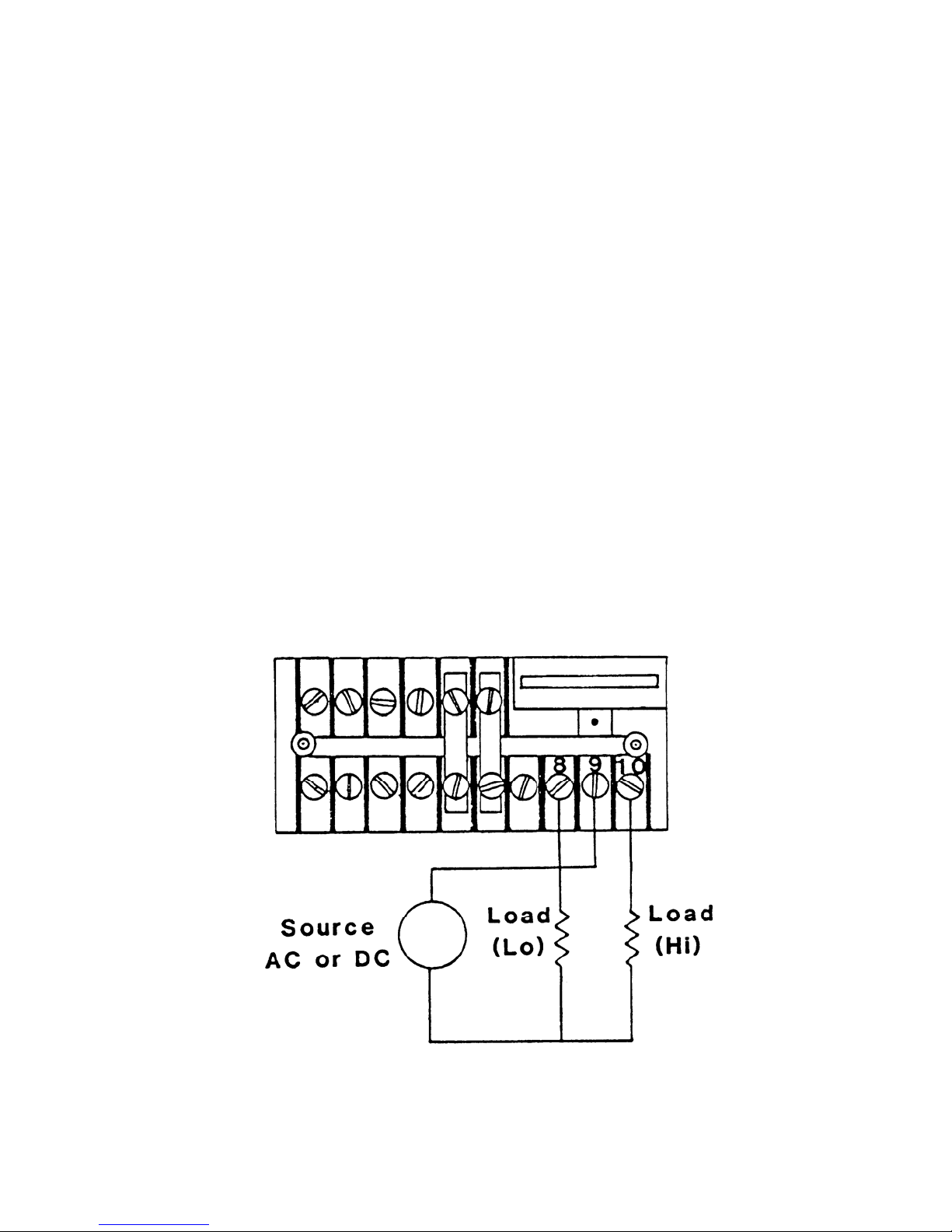
Figure 3.1 Relay Field Wiring Diagram
40
Page 41

Since the instrument has only two relays, and eight possible uses for those two relays,
there may be times when a relay is being asserted by more than one alarm. The relay actions
fall into three categories: Momentary; Transient; and Persistent. A Momentary action, as
the name implies, closes the relay for only a moment, then opens the relay. The Tap Change
Acknowledge is the only Momentary use of a relay. A Transient action is one that keeps the
relay closed as long as a condition remains valid. As soon as the condition goes away, the
relay will open. The High Tap & Low Tap Alarms and the FA 25 and FA 27 Error
Alarms are the only Transient uses of a relay. A Persistent action is one in which the relay
remains closed until it is manually reset by the operator. The Total Tap Change Count
Alarm, On-Tap Alarm, Up-To & Down-To Change Alarms, Pass Through Neutral
Alarm, One Direction Change Alarm are Persistent uses of a relay.
Relay Assertion Priority: Any Persistent relay action takes priority over any
Transient or Momentary action. The Tap Change Acknowledgement Relay can not be
assigned to the same relay as another alarm.
3.2.1 Tap Change Acknowledgement Relay
The 1250-LTC can momentarily close a relay contact following every detected tap
position change. The user can program a delay time of 0.1 to 9.9 seconds, which causes the
relay to wait before asserting. The user can also program a duration time of 0.1 to 9.9
seconds, which causes the relay to hold its assertion before turning off.
Use the OP 3, tCrLY, ACKRLY command to choose which relay output (OFF, LO
or HI) will be asserted following every tap position change. When this value is set to “OFF”
this function is disabled. Do not assign another alarm to the same relay assigned to for
Tap Change Acknowledgement. Use the OP 4, tCrdL, ACKDLY command to set the
delay time. Use the OP 5, tCrLt, ACKHOLD command to set the duration time.
3.2.2 High Tap Relay and Low Tap Relay
The 1250-LTC can close a relay contact when the LTC moves beyond programmable
upper and lower position limits. When the LTC tap position value reaches the Low Relay
limit, the assigned Low Tap Relay turns on, the appropriate Relay LED will light up, and the
alarm code “LOtAP” will be displayed momentarily. When the position value rises above the
Low Relay limit, the Low Tap Relay & LED will turn off and the alarm code will not be
displayed. When the tap position value reaches the High Relay limit the assigned High Tap
Relay turns on, the appropriate Relay LED will light up, and the alarm code “HItAP” will be
displayed momentarily. When the value falls below the High Relay limit, the High Tap Relay
& LED turn off and the alarm code will not be displayed. The user can separately program
which relays will assert for the upper and lower position limits.
Use the OP 15, rL Lt, LTLMT command to set the Low Tap Relay Limit and the
OP 17, rL Ht, HTLMT command to set the High Tap Relay Limit. Use the OP 16, LtrLY,
LTRLY command to select which relay (OFF, LO or HI) asserts when the Low Tap Relay
Limit is reached. Use the OP 18, HtrLY, HTRLY command to select which relay (OFF, LO
or HI) asserts when the High Tap Relay Limit is reached. These are Transient relay actions.
When these values are set to “OFF” this functions are disabled.
41
Page 42

3.2.3 Total Tap Change Count Relay
The 1250-LTC can count the number of tap position changes and turn on a relay and
LED when a programmed limit (10 to 999,990 counts) is reached. The alarm code “ttCLt”
will also be displayed momentarily. The counter can be pre-set to any number. A date can be
entered for reference purposes when the count is preset. (This date is stored in memory for
reference only, it will not increment as time passes. It can be read through the Front Panel or
the serial port.) The user can program which relay will assert when the Total Tap Change
Count limit is reached. Please note that the counter limit and pre-set values are set in
THOUSANDS of tap changes. For example, if an alarm is required at 125,000 operations,
set the alarm limit to “0125.0”. If it is known that the LTC already has 2,300 operations, preset the counter to “0002.3”.
Use the OP 55, ttCLt, TTCLMT command to set the Total Tap Change Count Limit.
Use the OP 56, ttrLY, TTCRLY command to select which relay (OFF, LO or HI) asserts
when the Total Tap Change Count Limit is reached. When this value is set to “OFF” this
function is disabled. Use the OP 57, ttPrE, TTCPRE command to pre-set the Total Tap
Change Counter value. If the alarm relay is asserted, it will be cleared when the counter is
preset to a value lower than the alarm limit. Use the OP 58, ttPdt, TTCDATE command to
enter a reference date. To do this using the programming menu: Select OP 58, ttPdt and
press the ENTER key. First, set the Day of the month value and press the ENTER key. Next,
set the Month value and press the ENTER key. Finally, set the Year value and press the
ENTER key. Use the OP 59, ttCdS, DUMP command to display the present counter value
and the reference date. The counter value will be displayed for 2 seconds, and then the date
will scroll across the display. This will repeat until the ENTER key is pressed, which will exit
the command.
3.2.4 On-Tap Alarm Relay
The 1250-LTC has the accuracy and resolution to monitor minute differences in LTC
tap position. Ideally, the LTC should always stop in the exact center of each tap position. A
properly functioning LTC should consistently stop within a tolerable band of degrees, with
every tap change. As the mechanism wears or if something breaks, the LTC may begin to
stop in positions further from the center of the tap position, on one or more taps.
The 1250-LTC can be programmed to give an alarm when it detects that the LTC has
stopped in a position that is outside the tolerable band of degrees. The width of this band of
tolerable error is programmable in degrees, with 0.1 degree resolution.
A three second time window is given for the LTC to be outside of the acceptable
Guard Band area. After three seconds, if the LTC is found in the “Error Zone”, the On-Tap
Alarm Relay will assert.
42
Page 43

Figure 3.2 On-Tap Example
Figure 3.1 is an example of an LTC with 10.0 degrees per tap position. This LTC
should stop at the “zero degrees” center point on every tap, plus or minus a programmable
tolerance (“Guard Band”) of 1.5 degrees (green area). If the LTC ever stops more than 1.5
degrees from the center (red area) of any tap, the On-Tap Alarm Relay will be asserted and an
LED will flash. The alarm code “OtGLt” will be displayed momentarily.
Use the OP 62, OtGLt, OTGDLMT command to set the On-Tap Guard Band
tolerance in degrees, +/- from zero. Use the OP 63, OtrLY, OTRLY command to select
which relay (OFF, LO or HI) asserts when the On-Tap Guard Band is reached. When this
value is set to “OFF” this function is disabled. Use the OP 63, OtdtE, OTDATE command
to enter a reference date.
Use the OP 65, OtdIS, DUMP command to display each tap and the highest
measured deviation for that tap. Use the UP and DOWN keys to scroll through the list of
taps. Press the ENTER key to select a tap and display its highest measured deviation in
th
degrees with 1/10
degree resolution and (-) sign (example: 1.3 or -0.9). Press the ENTER
key to return to the list of taps. Press the MENU key to escape back to the programming
menu.
Use the OP 66, Otdtd, command (menu only) to display all taps that exceed the
deviation limit. Press the ENTER key to display the measured deviation for each. Use the
UP and DOWN keys to scroll through the list of taps. Press the ENTER key to select a tap
and display its highest measured deviation. Press the Enter key to return to the programming
menu. Use the OP 67, OtrSt, OTRST command to reset all On-Tap logs. This command
will also clear an active On-Tap alarm.
43
Page 44

3.2.5 Up-To / Down-To Count Alarm Relay
Contacts in the LTC wear proportionately to the number of changes they endure. In
most LTC’s the contact surface used in changing Up-To a tap is different than the surface
used in changing Down-To the same tap. As the 1250-LTC is monitoring the movement of
the LTC, it will keep a log of how many times the LTC changes Up-To and Down-To each
tap. A programmable alarm limit (10 to 999,990 counts) can be set, which will assert the
assigned Alarm Relay output and light up the associated LED, if the number of logged
changes Up-To or Down-To any tap reaches the limit. The alarm code “udCLt” will be
displayed momentarily. Please note that the counter limit value is set in THOUSANDS of
tap changes. A date can be entered for reference purposes. (This date is stored in memory
for reference only, it will not increment as time passes. It can be read through the Front Panel
or the serial port.)
Use the OP 70, udCLt, UPDNLMT command to set the Up-To / Down-To Change
Alarm Limit. Use the OP71, udrLY, UPDNRLY command to select which relay (OFF, LO
or HI) asserts when the Up-To / Down-To Change Alarm Limit is reached. When this value
is set to “OFF” this function is disabled.
Use the OP 73, uddIS, DUMP command to display each tap, the Change Up-To
Count, and the Change Down-To Count for that tap. Use the UP and DOWN keys to scroll
through the list of taps. Press the ENTER key to select a tap and display its Change Up-To
Count. Press the ENTER key to display its Change Down-To Count. Press the ENTER key
to return to the list of taps. Press the MENU key to escape back to the programming menu.
The alarm relay will remain asserted until cleared or the counters are reset. Use the
OP 74, udCLr, UPDNCLR command to clear an active alarm without resetting the counters.
Use the OP 75, udrSt, UPDNRST command to clear the alarm and reset all Change Up-To
and Change Down-To counters. The display will read “rESEt”. When using the keyboard
command, press the UP and DOWN keys at the same time to confirm that you want to reset
these counters to zero. Press the MENU key to escape back to the programming menu
without clearing the counters.
3.2.6 Pass-Through-Neutral Alarm Relay
It is important that an LTC pass through the neutral tap(s) on a regular basis. As the
1250-LTC monitors LTC position, it knows when the LTC passes through the neutral tap(s).
The 1250-LTC is intelligent enough to know the difference between stopping at
neutral and reversing direction, and stopping at neutral and continuing on to the tap on the
opposite side of neutral. A timer is started each time a complete “Pass-Through-Neutral”
occurs. It counts the number of days since that event. When the LTC passes through neutral
again, the timer is reset and counting starts over. A programmable limit is set, which will
cause an assigned Alarm Relay output to assert and associated LED to light up, if the number
of days since a “Pass-Through-Neutral” reaches this limit. The alarm code “PtnLt” will be
displayed momentarily.
44
Page 45

Use the OP 85, PtnLt, PTNLMT command to set the “Pass-Through-Neutral” Alarm
Limit (0.1 to 365.0 days with 0.1 day resolution). Use the OP86, PtrLY, PTNRLY
command to select which relay (OFF, LO or HI) asserts when the “Pass-Through-Neutral”
Alarm Limit is reached. When this value is set to “OFF” this function is disabled. Use the
OP 87, PtdIS, DUMP command to display the number of days since the last “Pass-ThroughNeutral” occurred. The relay will remain asserted until the alarm is cleared. Use the OP 88,
PtnCL, PTNCLR command to reset the “Pass-Through-Neutral” counter. This command
will also clear an active “Pass-Through-Neutral” alarm.
3.2.7 One-Direction Change Alarm Relay
Typically, an LTC will move a few taps up or down, then reverse direction and move
a few taps, and reverse direction again. In most cases, it is unusual that the LTC will move
very many taps consecutively in one direction. If this occurs, it may indicate some sort of
failure in the position control system. The consequences of an out-of-control LTC could be
serious – especially in the case of parallel transformers.
As the 1250-LTC monitors LTC position, it can be programmed to assert an alarm
relay if it sees the LTC move too many taps consecutively in one direction, up or down. A
programmable alarm limit (2 to 50) can be set, which will cause an assigned Alarm Relay
output to assert and associated LED to light up, if the number of consecutive tap changes in
one direction reaches this limit. The alarm code “1dCLt” will be displayed momentarily.
Use the OP 90, 1dCLt, 1DTCLMT command to set the “One Direction Change”
Alarm Limit. Use the OP 91, 1drLY, 1DTCRLY command to select which relay (OFF, LO
or HI) asserts the FIRST TIME the “One Direction Change” Alarm Limit is reached. When
this value is set to “OFF” this function is disabled. Use the OP 93, 1ddIS, 1DTCDIS
command to display the number of days since the “One Direction Change” alarm was
asserted. The relay will remain asserted until the alarm is cleared. To clear the alarm, use the
OP 93, 1dACL, 1DACLR command.
3.2.8 FA 25 and FA 27 Alarm Relays
The 1250-LTC continuously performs sophisticated analysis of the input signal. If it
detects a loss of signal, it will display an error code “FA 25”. If it detects that the input signal
has been unstable (caused by noise or continuous LTC movement) for more than 5 seconds, it
will display an error code “FA 27”. These alarms can be programmed to “automatically
reset” when the condition is no longer valid. It can be programmed to assert an alarm relay
when each of these errors occurs. These are Transient relay actions.
Use the OP 53, Aut25, AUTO25 command to enable or disable the automatic reset
for the FA 25 error alarm. Use the OP 54, 25rLY, FA25RLY command to select which relay
(OFF, LO or HI) asserts while the FA 25 error is being displayed. Use the OP 60, Aut27,
AUTO27 command to enable or disable the automatic reset for the FA 27 error alarm. Use
the OP 61, 27rLY, FA27RLY command to select which relay (OFF, LO or HI) asserts while
the FA 27 error is being displayed.
45
Page 46

3.3 Serial RS-232 “-S”
The Serial RS-232 option on the Model 1250-LTC can be used to program the
instrument or to retrieve position data from the instrument. It is a full-duplex, DCE
configuration.
The communication port settings: baud rate, word length, parity, stop bits, and address
are programmable using the OP 80, POrt, PORT command. (See Table 2.1 and 2.2 for
command protocol and choices.)
NOTE: When the port is programmed for 2 Stop Bits, the Parity must be “NONE”.
There are seven operating modes for the serial RS-232 port:
Serial Disabled
the OP 51, RS232, SERIAL command to choose mode “0”. If you are programming the
instrument through the serial port, using the serial command mode, this “disabled” mode will
not take effect until the command “EXIT” is entered. The only way to de-select this
“disabled” mode is to use the menu command OP 51, RS232, and select another mode.
Data Logger Mode
value on the display (including sign) once a second. To select this mode use the OP 51,
RS232, SERIAL command to choose mode “1”. If you are programming the instrument
through the serial port, using the serial command mode, this mode will not take effect until
the command “RESTART” is entered.
Polled Mode When this mode is selected, the 1250-LTC can be interrogated at any
time via the RS-232 port for the current position. This is done by first instructing the
1250-LTC to latch the current position by transmitting an asterisk (*) to the unit. The position
is then extracted, one character at a time, by transmitting the digits 0 through 6. Zero causes
the sign character to be transmitted, 1 through 6 causes each position digit to be sent. The
decimal point, wherever it may be positioned, is considered to be a digit. To select this mode
use the menu command OP 51, RS232, SERIAL command to choose mode “2”.
Sampled Mode
time via the RS-232 port for current position by transmitting a question mark (?) to the
1250-LTC. When the 1250-LTC receives a question mark, it responds by latching the current
position and transmitting the value on the display in ASCII form. To select this mode use the
menu command OP 51, RS232, SERIAL command to chose mode “3”.
Serial Command Mode This mode enables programming the instrument through the
serial port. To select this mode use the menu command OP 51, RS232 to choose mode “4”.
When this mode is selected, no other serial communication can occur. In addition, if another
Serial mode is chosen it will not be activated until the “EXIT” command is given through the
serial port command line.
This mode stops all serial communication. To select this mode use
This mode causes the 1250-LTC to transmit the present position
When this mode is selected, the 1250-LTC can be interrogated at any
46
Page 47

MODBUS Mode When this mode is selected, the 1250-LTC will respond to
MODBUS commands via the serial port. This option requires the RS-485 (-M) or RS-232 (-S)
hardware option be installed. To select this mode use the menu command OP 51, RS232
command to choose mode “6”. (See Section 2.3, page 18 for programming instructions.)
Remote Display Driver Mode This mode must be used when the 1250-LTC is
connected to an INCON model RD4 Remote Display. It causes the 1250-LTC’s RS-232
output to transmit the proper protocol and timing for the RD4 to mimic what is on the
1250-LTC’s display. To select this mode use the menu command OP 51, RS232 command to
choose mode “7”.
3.4 Serial RS-485 Multi-Drop Option “-M”
The Serial RS-485 option on the Model 1250-LTC can be used to program the
instrument and to retrieve position data from the instrument, very much like the RS-232
option. It is a half-duplex configuration.
MODBUS is the most likely protocol to use for a 1250-LTC equipped with RS-485,
but the 1250-LTC with RS-485 will operate in all of the same serial modes listed above in
Section 3.3. Certain restrictions apply due to the nature of the half-duplex configuration: The
device communicating to the 1250-LTC must be able to turn off its transmitter very quickly
so that the 1250-LTC can respond over the same transmission lines. The Remote Display
Driver mode is not useful, since the model RD-4 will only accept an RS-232 signal.
Table 3.8 Wiring: Digital Connector Pin-Out
DB-25
Pin#
1 1 Chassis Gnd. Chassis Gnd.
14 2
2 3 Transmit (O) Data A(I/O) +
15 4
3 5 Receive (I) Data B(I/O) –
16 6
4 7 RTS (O) Not Used
17 8
5 9 CTS (I) Not Used
18 10
6 11
19 12
7 13 Signal Gnd. Signal Gnd.
20 14
8 15
21 16
9 17
22 18
10 19
23 20
1250-LTC
Pin#
RS-232
Function
RS-485
Function
47
Page 48

3.5 Input Isolation Option “-I”
The 1250-LTC may be ordered with isolated synchro input terminals. In cases where
there is a compromise of the (Controller, SCADA, etc…) analog input’s isolation to earth
ground, this Isolation Option will prevent AC voltage from becoming impressed upon the
1250-LTC’s analog output signal to that device. (See Note at the end of Section 3.1, page 39)
This option consists of two signal isolation transformers installed in the signal input circuitry.
Performance and reliability are not affected when this option is installed.
Please note that this option is not compatible with the Relay Option (-R). The “-I” and
“-R” options can not be installed simultaneously. They occupy the same space inside the
instrument. You must choose one or the other.
4.0 FIELD CALIBRATION & TEST
Calibration: The Model 1250-LTC should not require field calibration. However,
there are provisions in the menu to facilitate Signal Input Calibration and Analog Output
Calibration. Signal Input Calibration cannot be performed in the field; it is strictly an infactory function. The analog output may be adjusted in the field. A calibrated multi-meter
should be used to measure the output signal during calibration.
To enable analog calibration, select the OP 30, CAL menu command and choose the
“On” mode. If you are using the RS-232 serial port, use the ANACAL command. The
analog output may be forced to LOW, MID, and HIGH output signal states.
If menu commands are being used, select the OP 31, L CAL command to force the
analog output to LOW scale output. If you are using the RS-232 serial port, press the space
bar on the computer terminal. This toggles the output between LOW, MID, and HIGH
outputs. The display on the 1250-LTC should read “LO”. The analog output low scale may
now be adjusted by turning the “ZERO” pot, accessible through the slot in the left side of the
case (see Figure 4.1), until the output signal is reading properly on the multi-meter.
If menu commands are being used, select the OP 32, H CAL command to force the
analog output to HIGH scale output. If you are using the RS-232 serial port, press the space
bar on the computer terminal. The display on the 1250-LTC should read “HI”. The analog
output high scale may now be adjusted by turning the “SPAN” pot (see Figure 4.1) until the
output signal is reading properly on the multi-meter. Repeat analog LOW and HIGH
calibration steps several times to assure proper output signal calibration of both. Some
interaction may occur between the ZERO and SPAN adjustments.
If menu commands are being used, select the OP 33, D CAL command to force the
analog output to MID scale output. If you are using the RS-232 serial port, press the space
bar on the computer terminal. The display on the 1250-LTC should read “--”. The analog
output should read a mid-scale signal on the multi-meter. There is no adjustment for this midscale output.
48
Page 49

Figure 4.1 Analog Output Adjustment Pots
Self-Diagnostic Tests: The Model 1250-LTC regularly performs a number of selfcheck diagnostic tests and generates error codes in the form “FA n” and “ERR n” if it detects
an internal fault. The “n” number indicates the type of failure detected. See Section 5.0, page
50, for a full list of error codes and their explanation.
Power Fail: The 1250-LTC is designed to shut its microprocessor off when it detects
the line voltage falling below a fixed threshold, typically 85 to 105 / 170 to 210 VAC. This
feature enables the microprocessor to properly store its data before the power is lost
completely. The 1250-LTC will automatically re-start itself when the line voltage rises above
the Power Fail Threshold voltage.
The software revision number can be displayed by pressing the “SELECT/ENTER”
key while turning on the power to the 1250-LTC.
The 1250-LTC has the capability to delete all user-programmed values and restore all
factory default program values. This “cold boot” is accomplished by pressing the “MENU”
key while turning on the power to the 1250-LTC. There is no way to undo the effects of a
cold boot.
The LED display can be tested. Use the OP 40, LED t, LEDTEST command to turn
on all display LED’s. Press the ENTER key to stop the test.
The RS-232 port can be tested. Use the OP 41, RS t menu command to enter the
RS-232 Echo Test mode. With a computer terminal connected to the serial port, type in
some characters. The 1250-LTC should receive these characters and re-transmit them back to
the terminal. The characters typed should appear on the terminal display. Press the ENTER
key to stop the test.
The High / Low relays can be tested. Use the OP 43, RLY t, RLYTEST command to
turn on one of the relays. The UP and DOWN keys will cause the 1250-LTC to toggle
between the High and Low relay. If you are using the RS-232 serial port, press the space bar
on the computer terminal to toggle between the High and Low relay.
49
Page 50

5.0 ERROR CODES
Table 5.1 Error Codes
DISPLAY DESCRIPTION
FA 2
FA 3
FA 5
FA 20
FA 22
FA 25
FA 27
ERR 30
ERR 80
LOtAP
HItAP
ttCLt
OtGLt
udCLt
PtnLt
1dCLt
* This alarm needs to be reset, either manually or automatically. Use the OP 53, Aut25,
AUTO25 command to set the Automatic Reset to “On” or “Off”. When the Automatic Reset
is set to “Off”, press the MENU button to manually reset the alarm.
** This alarm needs to be reset, either manually or automatically. Use the OP 60, Aut27,
AUTO27 command to set the automatic reset to “On” or “Off”. When the Automatic Reset is
set to “Off”, press the MENU button to manually reset the alarm.
Watchdog Re-start
(Processor Crash If condition recurs, call the factory.)
Memory Error at start-up
(User programming is erased, factory program defaults are re-loaded.)
Keyboard Error at start-up
(UP or Down Key, or more than one key is being pressed during power-up.)
Input Calibration Error
(Input signal differential too large. Factory use only)
Internal Timer Failure
(Call the factory.)
Synchro input signal not present *
(Measure voltages at terminals A-C and B-C.)
Synchro input signal is not stable - never stops changing **
(The LTC is repeatedly changing taps, or there is noise present on the signal.)
Analog output calibration mode not enabled
(Change OP 30 to “On”.)
Serial Port Parameter Conflict
(Change Stop Bits or Parity setting.)
Alarm condition: the Low Tap position limit has been reached.
(The LTC position is lower than the Low Tap alarm limit.)
Alarm condition: the High Tap position limit has been reached.
(The LTC position is higher than the High Tap alarm limit.)
Alarm condition: the Total Tap Change counter limit has been reached.
(There have been too many tap changes – total Up and Down.)
Alarm condition: the On-Tap Guard band limit has been reached.
(One or more tap changes have stopped outside the acceptable position limit.)
Alarm condition: the Up-To / Down-To tap change counter limit has been
reached. (There have been too many changes up or down to one or more taps.)
Alarm condition: the Pass Through Neutral limit has been reached.
(There have been too many days without a Pass Through Neutral.)
Alarm condition: the One Direction tap change counter limit has been reached.
(There have been too many consecutive tap changes in one direction.)
50
Page 51

6.0 SPECIFICATIONS
(All values are typical, unless otherwise specified)
ENCLOSURE: RECTANGULAR PANEL MOUNTED INSTRUMENT
MATERIAL PLASTIC
SIZE 89mm W X 41.3mm H X 178mm D
BEZEL 112mm W X 62mm h X 17.5mm D
MOUNTING INTEGRAL SNAP-IN TABS
POWER INPUT:
CONNECTOR SCREW TERMINALS L1, L2, GND
VOLTAGE 115 VAC +/- 10%
OPTIONAL 230 VAC +/- 10%
FREQUENCY 47 TO 63 Hz
POWER CONSUMPTION 8 VA MAX
FUSE INTERNAL (3/8 AMP)
ISOLATION TRANSFORMER (1000 VAC)
TEMPERATURE RANGE
OPERATING 0 TO 55 DEG. C
DISPLAY 5 DIGIT, 7 SEGMENT LED WITH SIGN
0.56 INCH HEIGHT
FOUR STATUS INDICATOR LED’S
VIEWING DISTANCE 23 FEET
UPDATE RATE 10 TIMES PER SECOND
ACCURACY (25 DEG. C) +/- 10 ARC MINUTES W/ TYPICAL SYNCHRO
RESOLUTION 6 ARC MINUTES
TEMPERATURE DRIFT +/- 0.2 ARC MINUTES PER DEG. C WITH
TYPICAL SYNCHRO
ELECTRICAL INPUTS
SIGNAL INPUT 3 PHASE, 0 TO 90 VAC
(
PROGRAM DISABLE CONNECT TERMINAL #3 TO #4
ELECTRICAL OUTOUTS
OPTIONAL HI/LO RELAYS 2 ea. FORM 1A N.O.
3A @ 250 VAC (RESISTIVE)
1/10 HP @250VAC
3A @30 VDC (RESISTIVE)
TOTAL ISOLATION 1000 VAC
ANALOG OUTPUT
RESOLUTION 12 BITS (+/- 0.025% OF F. S.)
NON-LINEARITY +/-0.1% OF FULL SCALE
INPUT ISOLATION OPTIONAL)
51
Page 52

Model 1250-LTC
Installation & Programming Manual
52
 Loading...