

INCOE I Series, IC-15A Quick Start Manual
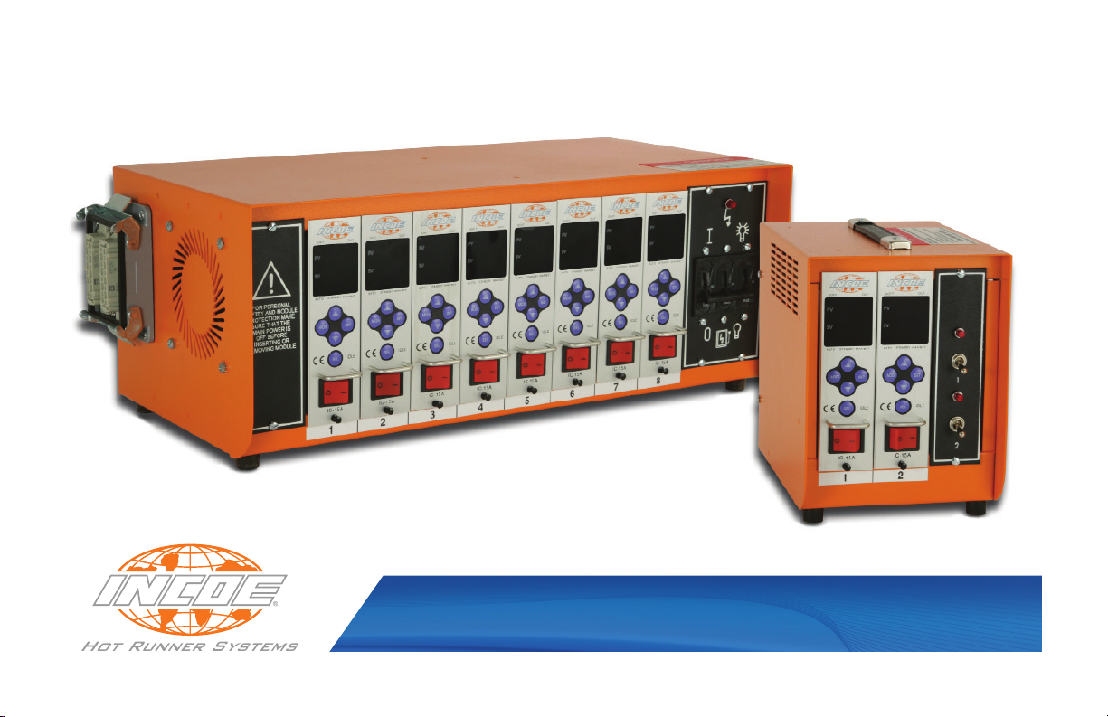
INCOE® I Series IC-15A Temperature Control Module
Quick Start Manual

All rights reserved, errors and omissions excepted. © INCOE® 2013
INCOE® Corp. Global Headquarters 1740 E. Maple Road Troy, Mi 48083 USA T: 248-616-0220 E: tech.support@incoe.com www.incoe.com
More Information
To view the full Operation Manual for
INCOE’s I Series IC-15A Temperature
Controller, visit us at www.incoe.com.
CONTROLLER SPECIFICATIONS
Input Power: 240/230 VAC single phase
Input Power Range: 90 - 250 VAC
Max. Output Power: 3600W (15 Amps)
Frequency: 60 Hz / 50 Hz
INSTRUCTIONS FOR INSTALLATION
INCOE® I Series IC-15A Temperature Control Module
Quick Start Manual
INITIAL START UP
Referencing the input power supply diagram on the
PC (Portable Control) Enclosure, connect the PC
Enclosure to the appropriate plant power supply with
suitable ground.
Inspect all wiring to and from the PC Enclosure.
With the power OFF, install the individual Control
Modules into the PC Enclosure. Note - to prevent
electrical shock or damage to the I Series Controller,
power to the PC Enclosure MUST be turned off when
installing or removing Control Modules.
Using the circuit breaker, turn on the PC Enclosure.
Turn on individual I Series Control Modules using the
power switch. Each Module will enter into an IDLE (IdL)
state. Thermocouple temperature is shown on the PV
display, and the Module will output 0% power.
Control Modules can be installed in industry standard PC
(Portable Control) Enclosures. Before installing individual
Control Modules, make certain each Module will t into
the PC Enclosure correctly and securely.
Contact INCOE® for assistance if necessary.
INCOE® Corp. Global Headquarters 1740 E. Maple Road Troy, Mi 48083 USA T: 248-616-0220 E: tech.support@incoe.com www.incoe.com
To enter into Automatic Operation from the IDLE (IdL)
state, press and hold the
The Control Module will now operate with its stored
parameters. To change these parameters, refer to this
manual’s tables.
SEL button for one second.
Page 1 of 5 12/02/2013
 Loading...