

Inception Machines ARCMILL Assembly Instruction Manual
Assembly Instruction
Guide
03/06/2019 Version 1.3

Part Number Descripon Quanty
E20 Nema 23 Stepper Motor Y2 1
ARCMILL Kit Contents
S1 40x40 Cross Beam 2
S2 40x40 1N Cross Beam 1
S3 40x80 Y-Axis Beam w/linear rail assembly 2
S4 40x120 Gantry Beam w/linear rail assembly 1
S5 4080 End Plate Standard 2
S6 4080 End Plate Reverse 2
S7 Gantry Upright Plate Le 1
S8 Gantry Upright Plate Right 1
S9 Z-Axis Rear Rail Mounng Plate 1
S10 Z-Axis Sffening Brace 2
S11 Spindle Mounng Plate 1
S12 Z-Axis Lead Screw Mounng Plate 1
S13 Y-Axis Lower Cable Chain Mount (fied with DC power enclosu
S14 Y-Axis Lower Cable Chain Rest 3
S15 Y-Axis Rail Cover Le 1
S16 Y-Axis Rail Cover Right 1
S17 Gantry Top Dust Cover 1
S18 Gantry Lower Dust Cover 1
S19 Gantry Side Skirt 2
S20 Y-Axis Motor Cover 2
S21 Dewalt Spindle Mount 2
S22 MDF Wasteboard (half) 2
re) 1
T1 Z-Axis MGN15H 250mm Linear Rail Assembly 2
T2 Z-Axis Lower Bearing Block 1
T3 HTD3M 15 Tooth Timing Pulley 3
T4 HTD3m 15mm Wide Timing Belt Set (823mm x2) (830mm x1) 1
T5 HTD3M
T6 9mm 150-GT2 Belt 1
T7 GT2 20T 9mm 6.35mm Bore Pulley 1
T8 Z-Axis leadscrew assembly (nut, FK06 bearing, gt2 pulley) 1
E1 XY Axis Limit Switch PCB Assembly Standard 2
E2 XY Axis Limit Switch PCB Assembly Reverse 3
E3 XY Axis Limit Switch PCB Assembly Standard Angled Socket 1
E4 Controller Assembly (w/enclosure, base plate, m3x8 buon head, F2F spacers, end plates, fan) 1
E5 USB C
E6 Nema 23 Stepper Motor X 1
E7 Nema 23 Stepper Motor Z 1
E8 Cable Conduit Set (980mm x2) (700mm x1) 1
E9 Cable Carrier Mount Open 6
E10 Cable Carrier Mount Standard 3
E11 Gantry Conduit Hook 1
E12 Z-Axis Microswitch Cable Retaining Clip 2
E13 Cable Tie Mount Base 3
E14 Power Supply 1
E15 Power Supply Mains Lead 1
E16 Microswitch Cable X-Axis 1
E17 Microswitch Cable Y-Axis 1
E18 Microswitch Cable Z-Axis 1
E19 Nema 23 Stepper Motor
Belt End Clamp w/nuts and set screws installed 6
able 1
Y1 1
1
Part Number Descripon Quanty
A4 1mm Spindle Mount Spacer 2
ARCMILL Kit Contents
F1 M3x12mm Cap Head Screw (40 screws used to install rails) 107
F2 M3x30mm Cap Head Screw 10
F3 M3x10mm Countersunk Screw 12
F4 M3x8mm Cap Head Screw 36
F5 M3x6mm Socket Buon Head Flange Screw 6
F6 M3 Penny Washer 2
F9 M3x12mm Buon Head Screw 4
F10 M4x12mm Set Screw 2
F11 M4x20mm Set Screw 4
F12 M4x8mm Countersunk Screw 7
F13 M4 Full Nut 8
F14 M4x35mm Set Screw 2
F15 M5x25mm Cap Head Screw 4
F16 M5x35mm Cap Head Screw 4
F17 M5x16mm Cap Head
F18 M6x16mm Cap Head Screw 16
F19 M6x10mm Cap Head Screw 4
F20 M6x55mm Cap Head Screw 2
F21 M8x20mm Buon Head Screw 6
F22 M8x25mm Countersunk Screw 14
F23 HNTT6-3 Misumi M3 T-Nut Pre Inseron (40 used to install rails) 38
F24 HNTT6-6 Misumi M6 T-Nut Pre Inseron (-1 assembly error) 13
F25 M6x12mm Pronged T-Nut 64
F26 M3x10mm Nylon Screw 4
F28 Y-Axis M5x10mm Spacers 8
F29 Nema 23 Idler Bearing Block Assembly (bearings, s
F30 X-Axis Motor Mount Bearing Spacer (2x bearings, circlips fied) 4
F31 XYZ Axis Limit Switch PCB Spacer 6
F32 Z-Axis Microswitch Striker 1
F33 3x7x20mm Hollow Spacer 4
F34 M5x10mm Set Screw
Screw 14
hims, screws fied) 2
A1 Extrusion Alignment Jig 1
A2 Cross Beam Spacer 1
A3 Cable Ties 10
Tools Required
- 1.5mm hex key
- 2.0mm hex key
- 2.5mm hex key
- 3.0mm hex key
- 4.0mm hex key
- 5.0mm hex key
- 7.0mm spanner
- Small flat blade screwdriver
2

Base Frame Assembly
3

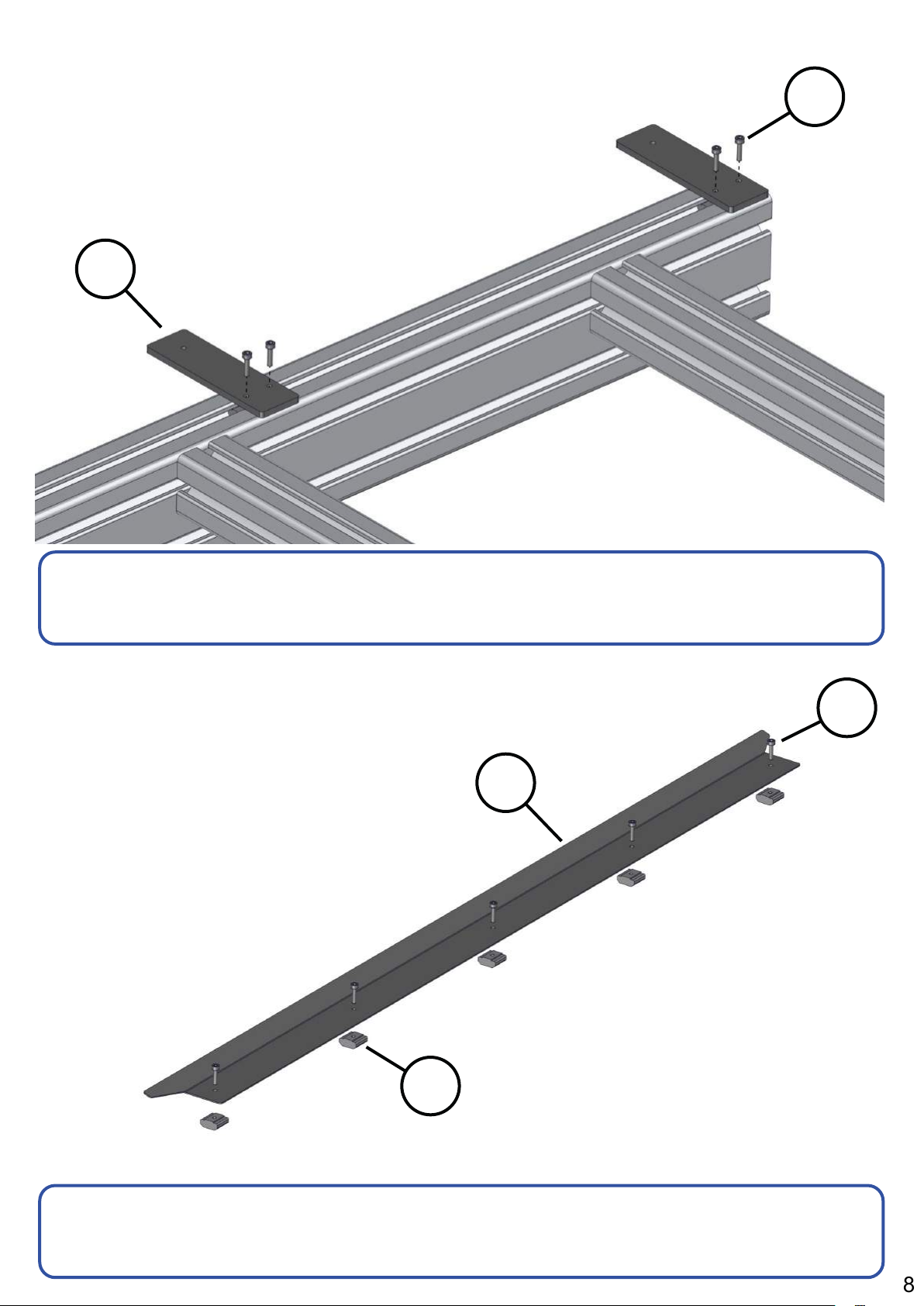
Step 1: Cross Beam Screws
S2
S1
F21
S1 (x2)
S2 (x1)
Insert (F21) screws into end holes in (S1) and (S2) beams
approximately 6mm from fully tight
Step 2: Cross Beam Wasteboard Nuts
F21 (x3)
F24
Insert 4x (F24) T-nuts into bottom slot of each cross beam
F24 (x12)
4
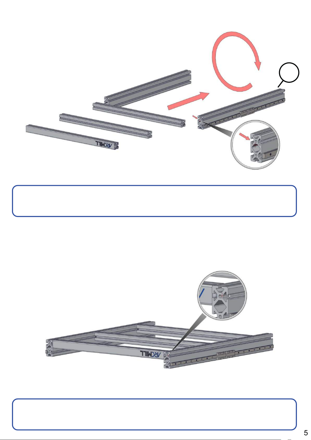
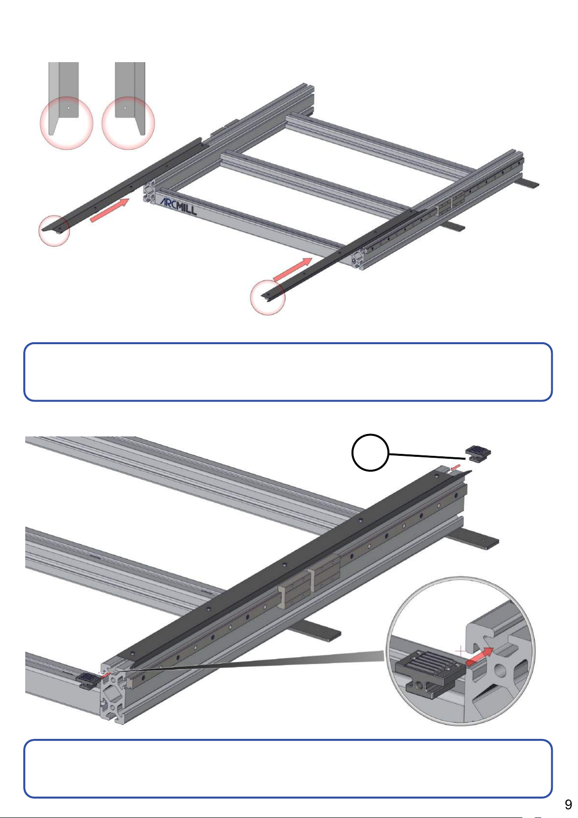
Step 3a: Cross Beam Install
S3
Start with Y-Axis beams (S3) inverted slide all cross beams into
upper slot of the Y-Axis beams
Step 3b: Cross Beam Install Positions
S3 (x2)
Align cross beams with side access holes in (S3) Y-Axis beams
5
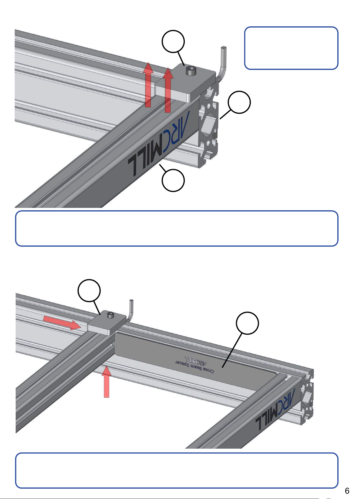
Step 4: Front Cross Beam Tightening
A1
S2
Use (A1) jig at all 6
cross beam
positions
S3
A1 (x1)
S2 (x1)
S3 (x1)
Position front cross beam (S2) flush with front of Y-axis beam (S3),
while applying upward pressure against (A1) tighten end screw
Step 5: Middle Cross Beam Position
A1
A2
A1 (x1)
A2 (x1)
While applying upward pressure on cross beam (S1) tighten end
screw through access hole, repeat process at remaining 3 positions
6

Step 6: Cable Carrier Nuts
S3
F23
Slide 4x (F23) T-nuts into upper slot of each Y-Axis beam (S3)
Step 7: Cable Carrier Mounting Brackets
S13
S14
F23 (x8)
F1
F1 (x4)
S13 (x1)
S14 (x1)
Position (S14) approximately 25mm/1 inch away from middle cross
beam, (S13) 10mm from end of beam, screw in place with (F1)
7
Step 8: Side 2 Cable Chain Mounting Brackets
S14
F1
S14 (x2)
Position (S14) approximately 25mm/1 inch away from middle cross
beam, (Rear S14) 10mm from end of beam, screw in place with (F1)
Step 9: Y-Axis Dust Covers Preparation
S15
F1 (x8)
F1
F1 (x5)
F23
Partially screw in (F1) screws though (S15) cover into (F23) T-nuts,
repeat for opposite cover (S16)
F15 (x1)
S16 (x1)
F23 (x5)
8
Step 10: Y-Axis Dust Cover Install
Left Right
Turn over base frame, slide both Y-Axis dust covers into the top
slot of the Y-Axis beams, align larger notch to front (circled)
Step 11: Belt Tensioning Clamps
T5
T5 (x4)
Slide on (T5) belt tensioning clamp into Base frame top slot, set
screw holes facing inwards. Repeat for all 4 corners.
9
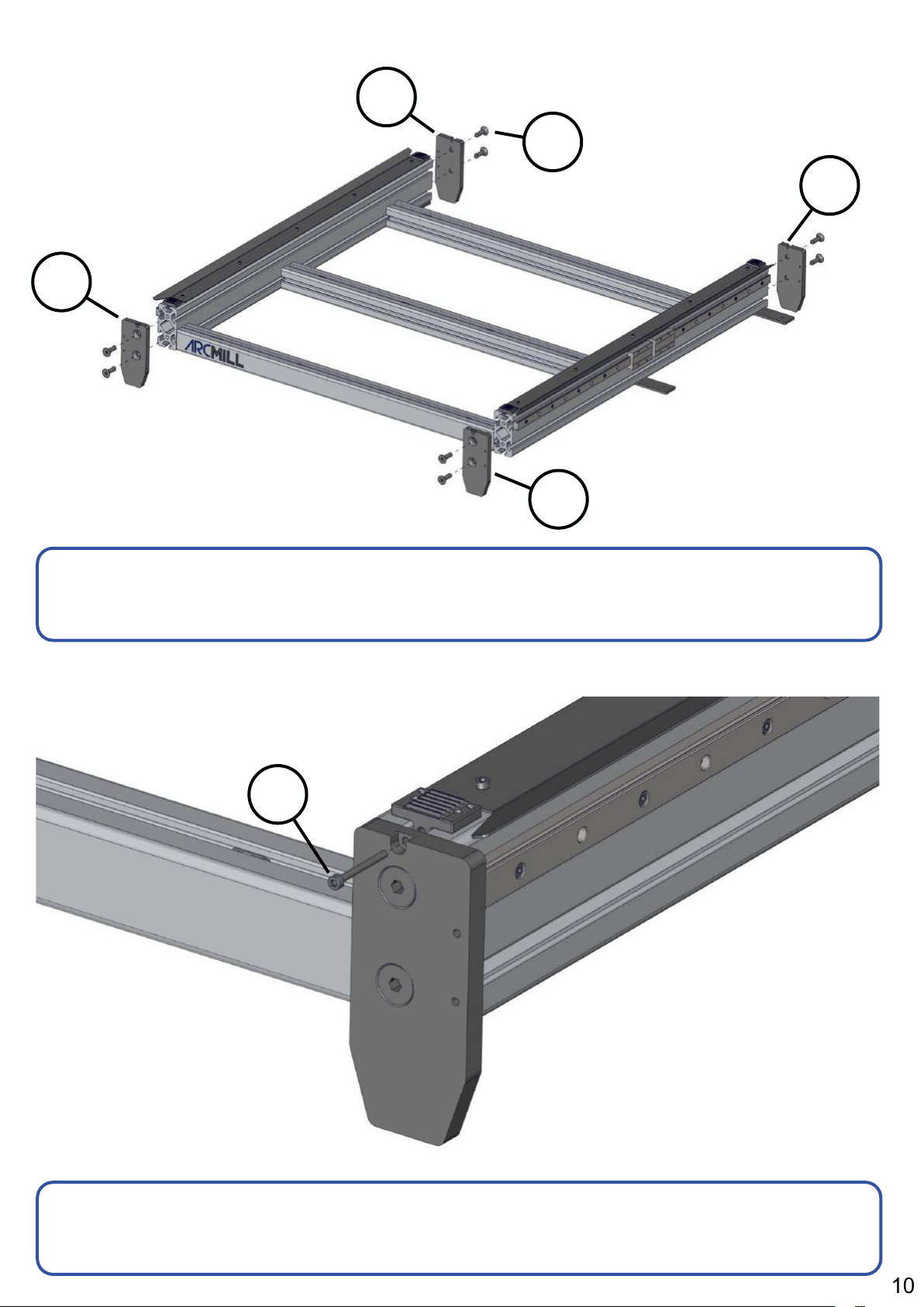
Step 12: Foot End Plates
S5
S6
F22
S5
S5 (x2)
S6 (x2)
S6
Screw on 4 end plates (S5 and S6) into Y-Axis beams using (F22)
screws. Tip: use foam packaging block to jack up frame
F22 (x8)
Step 13: Belt Tensioning Screw
F2
F2 (x4)
Using (F2) belt tensioning screw partially tighten in front end, fully
tighten rear belt clamps
10

Step 14: Wasteboard Mounting
S22
F18
F18 (x12)
S22 (x2)
Inset all (F25) wasteboard T-nuts prior to mounting to base. Screw
wasteboards (S22) down to cross beams using (F18) screws
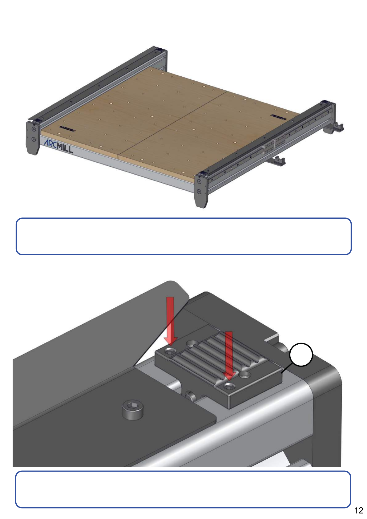
Step 15: Cable Carrier Mounts
F12
E9
E9 (x2)
F12 (x2)
Attach (E9) open cable carrier mount to lower brackets using (F12)
countersunk screws
11
Step 16: Complete Base Assembly
Set completed base assembly aside while assembling remaining
parts
Step 17: Belt Clamp Adjustment
T5
T5 (x4)
Attach (E9) open cable carrier mount to lower brackets using (F12)
countersunk screws
12

Gantry Upright Assembly
13
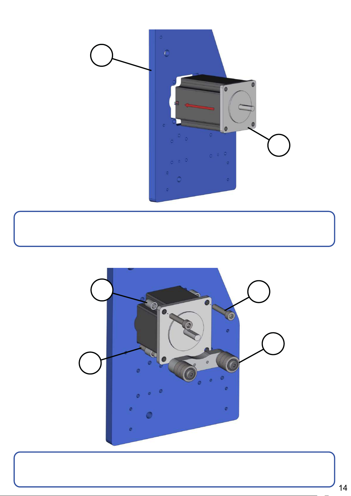
Step 1: Stepper Motor Install
S8
E19
S8 (x1)
Pass (E19) Y-Axis Motor and cable through portal in right hand
gantry plate (S8), orienting cable with rear notch
Step 2: Stepper Motor and Bearing Block Mounting
F28
F16
F15
F29
E19 (x1)
F15 (x2)
F16 (x2)
F28 (x4)
F29 (x1)
Insert spacers (F28) behind stepper motor flange, bolt though top
holes using (F15). Attach (F29) through bottom holes with (F16)
14
 Loading...