

Inca Metal Cutting Tasman DV Linear ESSENCE Installation And Operating Instructions Manual
Page 1
of 54
CERT # LC773211
TASMAN DV LINEAR FIREPLACE
26,000 BTU
Natural Gas
Installation and Operating Instructions
MODEL: ESSENCE
WARNING
IF THE INFORMATION IN TH
ESE INSTRUCTIONS IS
NOT FOLLOWED EXACTLY, A FIRE OR EXPLOSION
MAY RESULT CAUSING PROPER
TY DAMAGE,
PERSONAL INJURY, OR
DEATH
.
Do not store or use gasoline or other flammable
vapors and liquids in the vicinity of this or any other
appliance.
WHAT TO DO IF YOU SMELL GAS:
Do not try to light any appliance
Do not touch any electrical switch; do
not use
any phone in your building
Immediately call your gas supplier from a
neighbour s phone. Follow gas supplier s
instructions
If you cannot reach your gas supplier, call the
fire department.
Installation and service must be performed by a
qualified i
nstaller, service agency or gas
supplier.
WARNING: Improper installation, adjustment,
alteration, services or maintenance can cause injury
or property damage. Refer to this manual. For
assistance or additional information consult a
qualified installer, service agency or the gas
supplier.
D
UE TO HIGH TEMPERATU
RES
,
THE APPLIANCE SHOULD
BE
LOCATED OUT OF TRAFF
IC AND
AWAY FROM FURNITURE
AND
DRAPERIES
.
C
HILDREN AND ADULTS S
HOULD
BE ALERTED TO THE HA
ZARDS
OF HIGH SURFACE
TEMPERATURE AND SHOULD
STAY AWAY TO AVO
ID BURNS OR
CLOTHING IGNITION
.
Y
OUNG CHILDREN SHOULD
BE
SUPERVISED WHEN THEY
ARE IN
THE SAME ROOM AS THE
APPLIANCE
.
C
LOTHING OR OTHER
FLAMMABLE MATERIAL S
HOULD
NOT BE PLACED ON OR
NEAR THE
APPLIANCE
.
KEEP THE ROOM AREA C
LEAR AND
FREE FROM COMBUSTIBL
E
MA
TERIALS, GASOLINE, AND
OTHER FLAMMABLE VAPO
RS AND
LIQUIDS
.
PLEASE READ THIS MAN
UAL BEFORE INSTALLIN
G OR USING THIS APPL
IANCE.
SAVE
THIS MANUAL FOR FUT
URE REFERENCE.
Page 2
of 54
DV TASMAN FOYER LINEAR
AU GAZ NATUREL
Manuel D installation et Guide de l utilisateur
CERT # LC773211
AVERTISSEMENT
ASSUREZ-VOUS DE BIEN SUIVRE LES INSTRUCTIONS
DONNÉES DANS CETTE N
OTICE POUR RÉDUIRE AU
MINIMUM LE RISQUE D'
INCENDIE OU D'EXPL
OSION OU
POUR ÉVITER TOUT DOM
MAGE MATÉRIEL, TOUTE
BLESSURE OU LA MORT.
Ne pas entreposer ni utiliser d'essence ni d'autres vapeurs ou
liquids inflammables dans le voisinage de cet appareil ou de
tout autre appareil.
QUE FAIRE SI VOUS SENTEZ UNE ODEUR DE
GAZ:
Ne pas tenter d'allumer d'appareil.
Ne touchez à aucun interrupteur. Ne pas vous servir des
telephones se trouvant dans le bâtiment où vous vous
trouvez.
Appelez immédiatement votre fournisseur de gaz depuis
un voisin. Suivez les instructions du four
nisseur.
Si vous ne pouvez rejoindre le fournisseur de gaz,
appelez le service des incendies.
L'installation et l'entretien doivent être assurés par un
installateur ou un service d'entretien qualifié ou par le
fournisseur de gaz.
AVERTISSEMENT: Une mauv
aise installation, de réglage, la
modification, de services ou de maintenance peut causer des
dommages corporels ou matériels. Reportez-vous à ce
manuel. Pour toute assistance ou information supplémentaire,
consulter un installateur qualifié, un service ou
le fournisseur
de gaz.
E
N RAISON DE TEMPERAT
URES
ELEVEES, L'APPAREIL DOIT ETRE
PLACE HORS DE LA CIR
CULATION
ET LOIN DES MEUBLES
ET
TENTURES
.
E
NFANTS ET ADULTES DO
IVENT
ETRE AVERTIS DES DAN
GERS DE
LA TEMPERATURE DE SU
RFACE
ELEVEE ET DEVRAIT RE
STER A
L'ECART POUR EVITER LES
BRULURES OU L'INFLAMMATION
DES VETEMENTS
.
L
ES JEUNES ENFANTS DO
IVENT
ETRE SOIGNEUSEMENT
SURVEILLES QUAND ILS
SONT
DANS LA MEME PIECE Q
UE
L'
APPAREIL
.
C
LOTHING OR OTHER
M
ATERIAUX COMBUSTIBLE
S NE
DOIVENT
PAS
ETRE PLACES SUR
OU PRES DE L'APPAREIL
.
GARDER LA ZONE
SALLE
CLAIRE ET LIBRE DE M
ATERIAUX
COMBUSTIBLES
, D'
ESSENCE, ET
AUTRES VAPEURS ET LI
QUIDES
S'IL VOUS PLAIT LIRE
CE MANUEL AVANT D'I
NSTALLER OU UTILISER
CET APPAREIL.
CONSERVEZ CE MANUEL POUR REFERENCE FUTURE. THIS

Page 3
of 54
Table of Contents
IMPORTANT SAFETY INFORMATION
.. 4 - 5
1.0
INTRODUCTION
....................................................................................................................
1.1 Specifications, Appl
iance Dimen
sions & Installation Codes
..................................6 - 7
1.2 Features, Remote Control Functions
..................................................................8 - 10
1.3 Intended Use
...........................................................................................................11
1.4 General Safety
..................................................................................................
11 - 12
2.0
OPERATION
..........................................................................................................................
2.1 Lighting Instructions
.........................................................................................
13 - 14
3.0 INSTALLATION
.....................................................................................................................
3.1 Installation & Safety Notes
......................................................................................
15
3.2 Unpacking
...............................................................................................................
15
3.3 Installation
...............................................................................................................
15
3.3.1 Minimum Clearances
& Non Combustible Material Requirements ..................16
- 19
3.3.2 Gas Line Installation
...............................................................................................20
3.3.3 Direct Vent Information
....................................................................................
20 - 31
3.3.4 Rock & Glass Installation
..................................................................................
... 32
3.3.5 Door
Installation . .. 33 - 34
3.3.
6
Initial Firing .............................................................................................................34
3.3.
7
Manifold Pressure
....................................................................................................34
3.3.8 Primary Air Adjustment
....................................................................................
35 - 36
3.3.9 Altitude Adjustment
.................................................................................................36
3.3.1
0 Fan Access .. 37 - 39
3.3.1
1 Gas Valve Access ... 40
4.0 MAINTENANCE
....................................................................................................................
4.1 Maintenance Safety
................................................................................................41
4.2 Recommended Service
...........................................................................................
41
4.3 Glass Cleaning
.......................................................................................................
41
4.4 Burner & Pilot Cleaning
...........................................................................................
42
4.5 Valve & Pilot Replacement
....................................................................................
42
5.0 TROUBLE SHOOTING
. ..43 -
44
6.0
REPLACEMENT PARTS ...45
7.0
WARRANTY . ....46 -
48
8.0 LABEL INFORMATION .
. 49 - 50
APPENDIX A (INTERMIT
TENT PILOT & VALVE KIT) .... .51 - 54
Page 4
of 54
INSTALLER: Leave this manual with the
appliance.
CONSUMER: Retain this manual for future
reference.
INSTALLATEUR : Laissez cette notice avec
l appareil.
CONSOMMATEUR : Conservez cette notice
pour consultation ultérieure.
WARNING
Read this owner s ma
nual carefully and completely before trying to assemble, operate
or service this fireplace. Follow instructions for proper installation
Failure to install this appliance per the manufacturer s instructions or failure to use only
parts specifically approved
with this appliance may result in property damage or
personal injury.
Any change to this fireplace or its controls can be dangerous.
Improper installation or use of this fireplace can cause serious injury or death from fire,
burns, explosions, electrical
shock and carbon monoxide poisoning.
AVERTISSEMENT
Lisez ce manuel attentivement et complètement avant d'essayer de monter, utiliser ou
entretenir ce foyer. Suire les instructions pour assurer une bonne installation.
Risque de dommages ou de blessures si l appareil n est pas installé selon le
s
instructions du fabricant ou
si des pièces autres que celles spécifiquement approuvées avec
cet appareil sont utilisées
.
Tout changement à ce foyer ou à ses contrôles peuvent être
dangereux.
Une mauvaise installation ou l'utilisation de cette cheminée peut causer de
s blessures
graves ou la mort
par le feu, les brûlures, explosions, de chocs électriques et intoxication au
monoxyde de carbone.
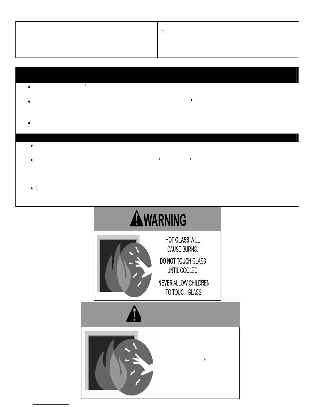
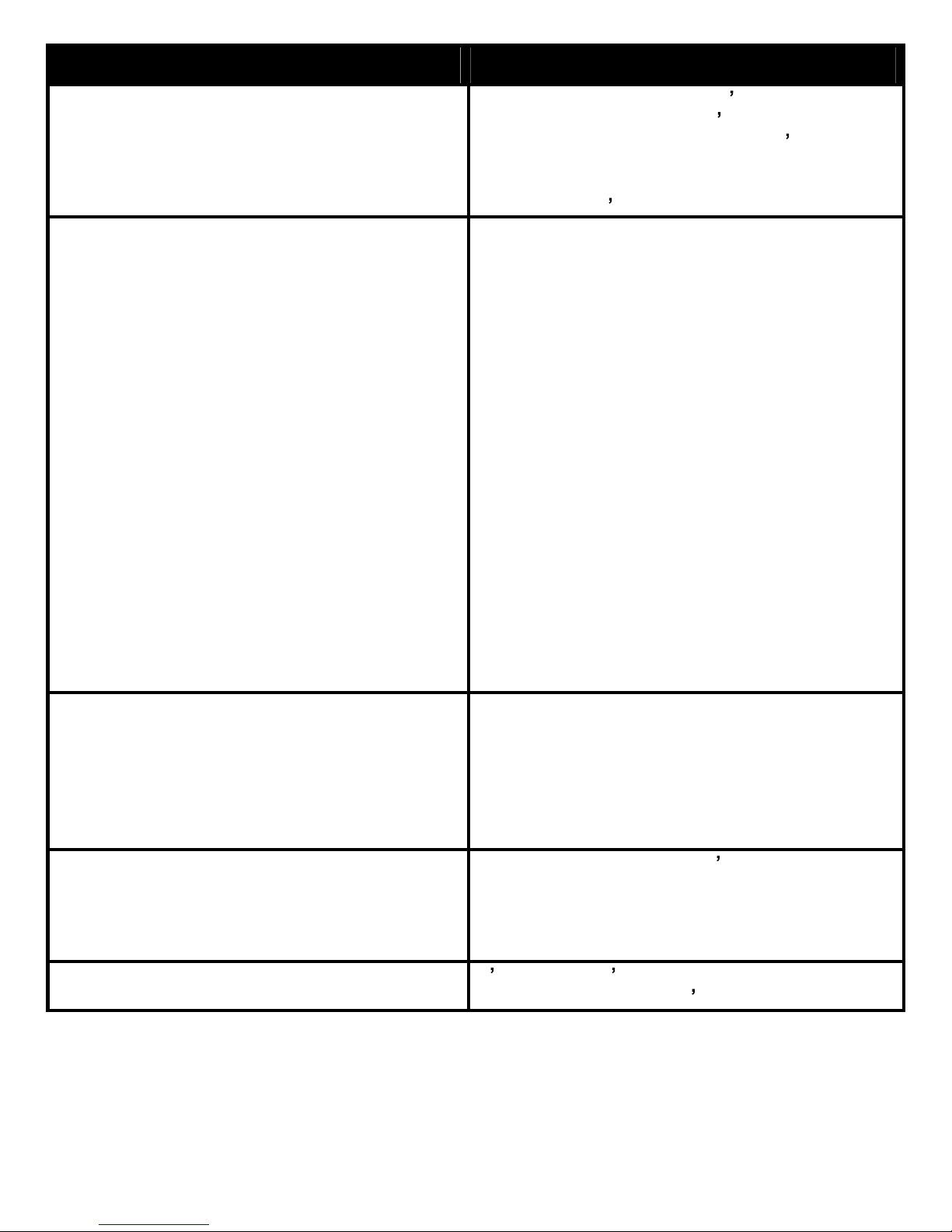
U
ne surface vitrée chaude
peut causer des brûlures.
Laisser refroidir l
a surface
vitr
ée avant d y toucher
Ne permettez jamais à un
enfant de toucher la
surface vitrée.
AVERTISSEMENT
Page 5
of 54
WARNING AVERTISSEMENT
Do no
t use this appliance if any part has
been under water. Immediately call a
qualified service technician to inspect the
appliance and to replace any part of the
control system and any gas control which
has been under water.
Ne pas utiliser cet appareil s il a été
plongé,
meme partiellement, dans l eau. Appeler un
technician qualifi
é pour inspecter l appareil et
remplacer toute partie du système de
commande et toute commande qui a
été
plong
ée dans l eau.
Toddlers, young children and others may be
susceptible
to accidental contact burns. A
physical barrier is recommended if there are
at risk individuals in the house. To restrict
access to a fireplace or stove install an
adjustable safety gate to keep toddlers,
young children and at risk individuals out of
the r
oom and away from hot surfaces.
Any safety screen or guard removed for
servicing an appliance must be replaced
prior to operating the appliance.
Installation and repair should be done by a
qualified service person. The appliance
should be inspected before
use and at least
annually by a professional service person.
More frequent cleaning may be required due
to excessive lint from carpeting, bedding
material, et cetera. It is imperative that
control compartments, burners and
circulating air passageways of
the appliance
be kept clean.
Les tout-petits, les jeunes enfants et d'autres
peuvent être sensibles aux brûlures par
contact accidentel. Une barrière physique est
recommandé s'il ya des personnes à risque
dans la maison. Pour restreindre l'accès à une
chem
inée ou un poêle installer une barrière de
sécurité réglable pour garder les tout-petits,
les jeunes enfants et les personnes à risque de
la salle et à l'écart des surfaces chaudes.
Tout écran ou grille de protection pour
l'entretien d'un appareil doit êtr
e remplacé
avant de faire fonctionner l'appareil.
Installation et réparation doit être effectuée par
un technicien qualifié. L'appareil doit être
inspecté avant son utilisation et au moins
annuellement par un technicien qualifié. Un
nettoyage plus fréquent
peut être nécessaire
en raison de peluches provenant des tapis,
literie, etc. Il est impératif que les
compartiments de contrôle, les brûleurs et les
conduits d'air de l'appareil soient gardés
propres.
This fireplace is a vented product. This
fireplace m
ust be properly installed by a
qualified service person. The glass door
must be properly seated and sealed. If this
unit is not properly installed by a qualified
service person with the glass door properly
seated and sealed gas leakage can occur.
Ce foyer
est un produit ventilé. Ce foyer doit
être correctement installé par un technicien
qualifié. La porte en verre doivent être placés
correctement et scellé. Si cet appareil n'est
pas correctement installé par un technicien
qualifié avec la porte en verre bie
n en place et
des fuites de gaz scellés peuvent se produire.
Caution: Label all wires prior to
disconnection when servicing controls.
Wiring errors can cause improper and
dangerous operation.
Attention
: Au moment de l entretien des
commandes, étiquetez t
ous les fils avant de
les débrancher. Des erreurs de c
âblage
peuvent entraîner un fonctionnement
inadéquate et dangereux.
Verify proper operation after servicing
S assurer que l appareil fonctionne
ad
équatement une fois l
entretien termin
é
Page 6
of 54
1.0 INTRODUCTION
1.1
SPECIFICATIONS
TABLE 1
ITEM
NATURAL GAS (NG)
INPUT: Hi
26,000 Btu/hr (7.62 kW)
INPUT: Lo
10,500
Btu/hr (
3.07
kW)
MANIFOLD PRESSURE: Hi
COLLECTEUR DE PRESSI
ON: FORT
3.5 w.c. (0.87 kPa)
MANIFOLD PRESSURE: Lo
COLLECTEUR DE PRE
SSION: FAIBLE
1.7 w.c. (0.42 kPa)
Minimum: 5.0 w.c. (1.2 kPa)
GAS INLET SUPPLY PRESSURE:
ENTREE DE PRESSION
Maximum: 13.5 w.c. (3.4 kPa)
ORIFICE SIZE: @ 0
-4500
FORMAT D'ORIFICE:
# 39 DMS
VALVE ORIFICE @ 0
-4500
SOUPANGE D ORIFICE:
# 50 DMS
A
IR SHUTTER
VOLET DE LAIR
OPEN
1/8
min
(
3.175mm
)
CONTROL VALVE TYPE:
TYPE DE SOUPAPE
Skytech AF-40004
VENTING
ÉVACUATION
2-
ply aluminum vent
Simpson Duravent or Security Venting
FAN
VENTILATEUR
Variable Speed (120 Volt)
THIS APPLIANCE IS ONLY
FOR USE WITH THE TYP
E OF GAS INDICATED O
N THE RATING
PLATE
. THIS APPLIANCE IS
NOT CONVERTIBLE FOR
USE WITH ANY OTHER G
ASES.
CET APPAREIL DOIT ET
RE UTILISE UNIQUEMEN
T AVEC LE TYPE DE GAZ INDIQUE SUR LA
PLAQUE SIGNALETIQUE.
CET APPAREIL NE PEU
T ETRE CONVERT
I A D AUTRES GAZ.
Page 7
of 54
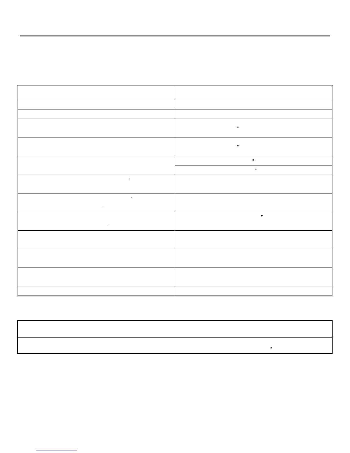
APPLIANCE DIMENSIONS
Figure 1
INSTALLATION CODES
This appliance is a Direct Vent appliance which draws all combustion air from outside the building
through an intake vent pipe.
Installation must conform to local codes. In the absence of local codes, installation must conform to
the
National Fuel Gas Code ANSI Z223.1/NFPA 54, or the current Natural Gas and Propane
Installation Code B149.1. The unit, when installed, must be electrically grounded in accordance with
loc
al codes or, in the absence of local codes, with the National Electric Code ANSI/NFPA No.70 or
with the current Canadian Electrical Code CSA C22.1. In the state of Massachusetts, this product
can only be installed by a licensed plumber or a licensed gas fitter. Failure to comply will void the
warranty.
This appliance has been certified for use with natural gas
.
This appliance is not for use with solid fuels.
CODES D'INSTALLATION
Cet appareil est un appareil à évent direct, qui attire tous l'air de combustion provenant de l'extérieur
du bâtiment par une entrée d'évent.
L'installation doit se conformer aux codes locaux. En l'absence de codes locaux, l'installation doit
être conforme au National Fuel Gas Code ANSI Z223.1/NFPA 54, ou le gaz naturel actuel et le Code
d'installation du propane B149.1. L'unité, une fois installé, doit être électriquement à la terre
conformément aux codes locaux ou, en l'absence de codes locaux, avec le National Electric Code
ANSI / NFPA No.70
ou avec l'actuel
Code
canadien de l
'électricité CSA C22.1
Cet appareil a été certifié pour une utilisation avec du gaz naturel et le propane.
Cet appareil n'est pas pour une utilisation avec des combustibles solides.
19.022
37.935
10.045
19.446
3.992
6.999
1.088
16.171
49.000
33.625
13.850
28.515
8.030
COLLAR MUST BE 304
STAINLESS STEEL
MATERIAL, MINIMUM
24 GA THICKNES
S

Page 8
of 54
1.2 FEATURES
Electronic Valve:
Automatic DC valve with AC power adapter. Hand held remote control.
Fan control
Variable speed control:
For units equipped with a fan control,
adjust speed by remote
control settings 1-6
Supreme Remote Control
Functional Operation Matrix
Initial Setup
Installation of (2) AAA-siz
e batteries will activate the setup mode. Setup mode can also be activated by
pressing the FLAME REAR and PROG/TIME buttons simultaneously for 5 seconds. The control will exit
setup mode if no button is pressed for 20 seconds. Appropriate icon on LCD w
ill flash when ready for
setup.
Press the UP or Down button in setup mode to change the temperature scale. Press SET button to skip
or advance to Fuel Type setup.
Press the UP or DOWN button to switch control from Natural to LP, or LP to Natural Gas. Pre
ss SET
button to skip or advance to Clock setup.
Press the UP or Down Button to set the hour. Press SET to advance to minutes.
Press the UP or Down button to set minutes. Press SET to advance to AM or PM.
Press the UP or Down button to set AM or PM. Press the SET button to advance to the day of week.
Use UP or Down button to select the day of the week.
The control will exit setup mode in 20 seconds.
MODE Button
The MODE button cycles the unit through the basic operational modes.
When off, press and r
elease the MODE button to turn the unit on in Manual mode.
Press and release the MODE button again, and the unit will operate in the Thermostat mode.
Press and release the MODE button again, and the unit will turn off.
Program Mode
The Program function i
s controlled by the PROG/TIME button. The control may be programmed for up to
two settings for weekdays and two settings for weekends. The control is preset to factory settings.
When the Program Mode is activated, the unit will automatically be operating
in the Thermostat Mode.
The unit will turn on or off based upon room and set temperature.
To activate the Program mode, press and release the PROG/TIME button.
To change the settings for the Program mode, press and hold the PROG/TIME button for 5 seconds
. The
program feature will flash at the top of the screen.
Press the UP or DOWN button to change the setting of the weekday (MTWTF) P1 ON. Press and release
the SET button.

Page 9
of 54
Press the UP or DOWN button to change the setting of P1 OFF. Press and release th
e SET button.
Press the UP or DOWN button to change the setting of P2 ON. Press and release the SET button.
Press the UP or DOWN button to change the setting of P2 OFF. Press and release the SET button.
Press the UP or DOWN button to change the setting of
the weekend (SS) P1 ON. Press and release the
SET button.
Press the UP or DOWN button to change the setting of P1 OFF. Press and release the SET button.
Press the UP or DOWN button to change the setting of P2 ON. Press and release the SET button.
Press
the UP or DOWN button to change the setting of P2 OFF. Press and release the SET button.
The Program Mode has been re-programmed.
Countdown Timer
The Countdown Timer Mode allows the control to operate the unit for up to 3 hours, in 10-minute
increments. It can be operated in either the Manual or Thermostat Modes.
To enter Timer Mode, press and release the TIMER button. The Timer icon will flash.
Press the UP or DOWN button to set the running time, in 10-minute increments. Press and release the
SET button. The timer will run for the set time duration.
Pressing the TIMER button while in Timer Mode will terminate the Timer operation. The Timer operation
will also terminate if the MODE button is cycled to off.
Thermostat Mode
The unit is placed in Therm
ostat Mode using the MODE button. Placing the unit in Thermostat Mode will
activate the numbers in the smaller window on the LCD screen.
Press the UP or DOWN button to change the thermostat set temperature. When the desired set
temperature appears, press
and release the SET button to set.
If the SET button is not pressed, the set temperature will automatically be set after 5 seconds.
The Thermostat Mode can be de-activated by pressing the MODE button.
Thermostatic Flame Modulation
This control can per
form Main Flame Modulation using the Thermostat. The control will shut the unit off
when the room temperature reaches 2
above set temperature. The Thermostat will automatically
modulate the main flame
:
Manual Flame Modulation
Main Flame
To change
the Flame Level manually, press the FLAME MAIN button. The current level will show in the
MAIN box on the LCD screen.
Press the UP or DOWN button to change the Flame Level.
When the unit is turned on, whether in Manual, Thermostatic, or Program Mode, the
Main Flame will
automatically ignite at the High (7) setting. After 5 seconds, the flame will default to the previous setting.
Fan Control
The unit must be ON to operate the Fan.
The Fan will turn on after 5 minutes of operation. Once the Fan comes o
n, it can be controlled using the
FAN button.
Press the FAN button, and the fan icon and speed will appear on the LCD screen.
Press the UP or DOWN button to control the fan speed (0-6). Press the DOWN button until 0 Level is
reached to turn the Fan off.

Page 10
of 54
The fan will run for 12 minutes after the unit is shut off in any mode. The fan may not be controlled during
this period.
Continuous Pilot
The unit can be changed from Intermittent Pilot Ignition (IPI), to Continuous, or standing, pilot.
To place the u
nit in continuous pilot mode, press and release the PROG/TIME
and
the FLAME MAIN
buttons
simultaneously
. Continuous Pilot will appear on the LCD screen.
Repeat the simultaneous PROG/TIME and FLAME MAIN push to place the unit back in IPI mode.
This feature
can also be activated by the Continuous Pilot (On/Off) switch on the Main Module.
Child Lock-Out
The Child Lock-out feature can be activated by pressing the PROG/Time
and
UP buttons
simultaneously
.
CP will appear on the LCD screen, and no signals can b
e sent from the transmitter.
To take the control out of Child Lock-out mode, repeat the above step. CP will disapper from the screen.
Learn Function
To program the system to a transmitter, press the LEARN button on the Main Module. A single audible
bee
p will be heard.
Press the MODE button on the transmitter to learn the transmitter to the system. A series of beeps will be
heard.
Up to two additional (NON-THERMOSTATIC) transmitters can be used simultaneously. To learn
additional transmitters, press an
d release the learn button again, and press the on button on the additional
transmitters.
To clear all transmitters and start over, press and hold the LEARN button for 10 seconds. A series of
three beeps will be heard, and the system is clear.
Low Batter
y Indicator
A low battery icon will appear on LCD screen when transmitter batteries reach low voltage level.
Thermal Safety
When the internal components of the Main Module reach 170
F, the unit will automatically shut off, and
send a repetitive audible
signal. The unit can be turned back on when the module cools below 160
Communication Safety
When in the Thermostat or Program Mode, the transmitter will send a silent signal to the module every 15
minutes. If a signal is not received within 2 hours du
e to dead batteries, lost transmitter, or transmitter out
of range, the unit will automatically shut down, and the module will send a repetitive audible signal.
Page 11
of 54
1.3 INTENDED USE
/
USAGE PROPOSÉ
This appliance is intended to be used as a zero cleara
nce fireplace.
Cet appareil est destiné à être utilisé comme un foyer à dégagement zéro.
1.4 GENERAL SAFETY
/
SÉCURITÉ GÉNÉRALE
Maintain adequate clearances around air openings into the combustion chamber.
Respecter les distances minimales convenable
s autour des bouches d'air dans la chambre de combustion.
Maintain adequate accessibility clearances for servicing and proper operation.
Respecter les distances minimales d'accessibilité suffisante pour l'entretien et bon.
This appliance shall not be conn
ected to chimney flue serving a separate solid-fuel burning appliance.
Cet appareil ne doit pas être raccordé à une cheminée desservant un autre appareil brûlant des combustibles
solides.
The appliance area must be kept clear and free from combustible materials, gasoline and other flammable liquids
and vapors.
La zone appareil doit rester clair et exempt de matériaux combustibles, essence et autres vapeurs et liquides
inflammables.
The flow of combustion and ventilation air shall not be obstructed.
Le débit
de combustion et de ventilation ne doit pas être obstrué.
The combustion air supply shall be in the same pressure zone as the drafthood relief opening on an appliance
equipped with a drafthood or as the vent outlet on an appliance not equipped with a draf
thood.
L'alimentation en air de combustion doit être dans la zone même pression que l'ouverture de secours hotte à air
sur un appareil équipé d'une hotte à air ou que l'évent de sortie sur un appareil n'est pas équipé d'une hotte à air.
Do not use this appliance if any part has been under water. Immediately call a qualified service technician to
inspect the appliance and to replace any part of the control system and any gas control which has been under
water.
Ne pas se servir de cet appareil s il a été plongé dans l eau, même partiellement. Faire inspecter l appareil par un
technicien qualifié et remplacer toute partie du système de contrôle et toute commande qui ont été plongées dans
l eau.
IMPORTANT
PLEASE READ THE FOLLOWING CAREFULLY
It is normal for fireplaces fabricated of steel to give off some expansion and/or contraction noises
during the start up or cool down cycle.
It is not unusual for gas fireplaces to give off some odors the first time they are burned. This is
due to the oils and sealants in
the manufacturing process.
PLEASE ENSURE YOU ROOM IS WELL VENTILATED DURING BURN OFF
OPEN ALL WINDOWS
It is recommended that you burn your fireplace for at least 4 (four) hours the first time you use it.
IMPORTANT
S'IL VOUS PLAÎT LIRE ATTENTIVEMENT CE
QUI SUIT
Il est normal pour les foyers fabriqués d'acier à dégager une certaine expansion et
/ ou des bruits
de contraction
pendant le démarrage ou cycle de refroidissement.
Il n'est pas inhabituel pour les foyers à gaz de dégager certaines odeurs la prem
ière fois qu'ils
sont brûlés.
Cela est dû aux huiles et produits d'étanchéité dans le processus de fabrication.
S'IL VOUS PLAÎT VOUS ASSURER pièce est bien aérée pendant BRÛLER - Ouvrir toutes les
fenêtres
Il est recommandé que vous brûlez votre foyer pend
ant au moins 4 (quatre) heures la première
fois que vous l'utilisez.
Page 12
of 54
WARNING
Hot while in operation. Do Not Touch. Severe burns may result. Keep children, clothing,
furniture, gasoline and other liquids having flammable vapors away.
Toddlers, young
children and others may be susceptible to accidental contact burns. A
physical barrier is recommended if there are at risk individuals in the house. To restrict
access to a fireplace or stove install an adjustable safety gate to keep toddlers , young
children
and at risk individuals out
of the room and away from hot surfaces.
Any safety screen or guard removed for servicing an appliance must be replaced prior to
operating the appliance.
Installation and repair should be done by a qualified service pe
rson. The appliance should
be inspected before use and at least annually by a professional service person. More
frequent cleaning may be required due to excessive lint from carpeting, bedding material, et
cetera. It is imperative that control compartmen
ts, burners and circulating air passageways
of the appliance be kept clean.
AVERTISSEMENT
L appareil est chaud lorsqu il fonctionne. Ne pas toucher l appareil. Risque de brûlures
graves. Surveiller les enfants. Garder les vêtements, les meubles, l essenc
e ou autres
liquides produisant des vapeur inflammables loin de l appareil.
Les tout-petits, les jeunes enfants et d'autres peuvent être sensibles aux brûlures par
contact accidentel. Une barrière physique est recommandé s'il ya des personnes à risque
dans
la maison. Pour restreindre l'accès à une cheminée ou un poêle installer une barrière
de sécurité réglable pour garder les tout
-petits, les jeunes enfants et les personnes à risque
de la salle et à l'écart des surfaces chaudes.
Tout écran ou grille de pro
tection pour l'entretien d'un appareil doit être remplacé avant de
faire fonctionner l'appareil.
Installation et réparation doit être effectuée par un technicien qualifié. L'appareil doit être
inspecté avant son utilisation et au moins annuellement par un technicien qualifié. Un
nettoyage plus fréquent peut être nécessaire en raison de peluches provenant des tapis,
literie, etc. Il est impératif que les compartiments de contrôle, les brûleurs et les conduits
d'air de l'appareil soient gardés propres.
Page 13
of 54
2.0 OPERATION
2.1
LIGHTING INSTRUCTIONS - for Intermittent Pilot
FOR YOUR SAFETY, READ BEFORE LIGHTING
WARNING: If you do not follow these instructions exactly, a fire or explosion may result causing property
damage, personal injury or loss of life.
A. This appliance is equipped with an ignition device which automatically lights the pilot. Do not try to light the pilot by hand.
B.
BEFORE LIGHTING smell all around the appliance area for gas. Be sure to smell next to the floor because some gas is he
avier than air and will
settle on the floor.
WHAT TO DO IF YOU SMELL GAS
Do not try to light any appliance.
Do not touch any electric switch; do not use any phone in your building.
Immediately call your gas supplier from a neighbour s phone. Follow the gas supplier s instructions.
If you cannot reach your gas supplier, call the fire department.
C. Use only your hand to push in or turn the gas control knob. Never use tools. If the knob will not push in or turn by hand, don t try to repair it, cal
l a
qualified service technician. Force or attempted repair may result in a fire or explosion.
D.
Do not use this appliance if any part has been under water. Immediately call a qualified service technician to inspect the appliance and to replace
any part
of the control system and any gas control which has been under water.
LIGHTING INSTRUCTIONS
1. STOP!
Read the safety information above on this label.
2. Set the thermostat to the lowest setting.
3. Turn off all electric power to the appliance.
4.
Do not attempt to light the pilot by hand.
5. Wait five (5) minutes to clear out any gas. Then smell for gas, including near the floor. If you smell gas, STOP! Follow B in the safety
information above o
n this label. If you don t smell gas, go to the next step.
6.
Turn on all electric power to the appliance.
7.
Set thermostat to desired setting (or switch to "ON" if not using a thermostat).
8. If the appliance will not operate, follow t
he instructions "To Turn Off Gas To Appliance" and call your service technician or gas supplier.
TO TURN GAS OFF TO APPLIANCE
1.
Set thermostat to lowest setting.
2.
Turn
on/
off
switch to off.
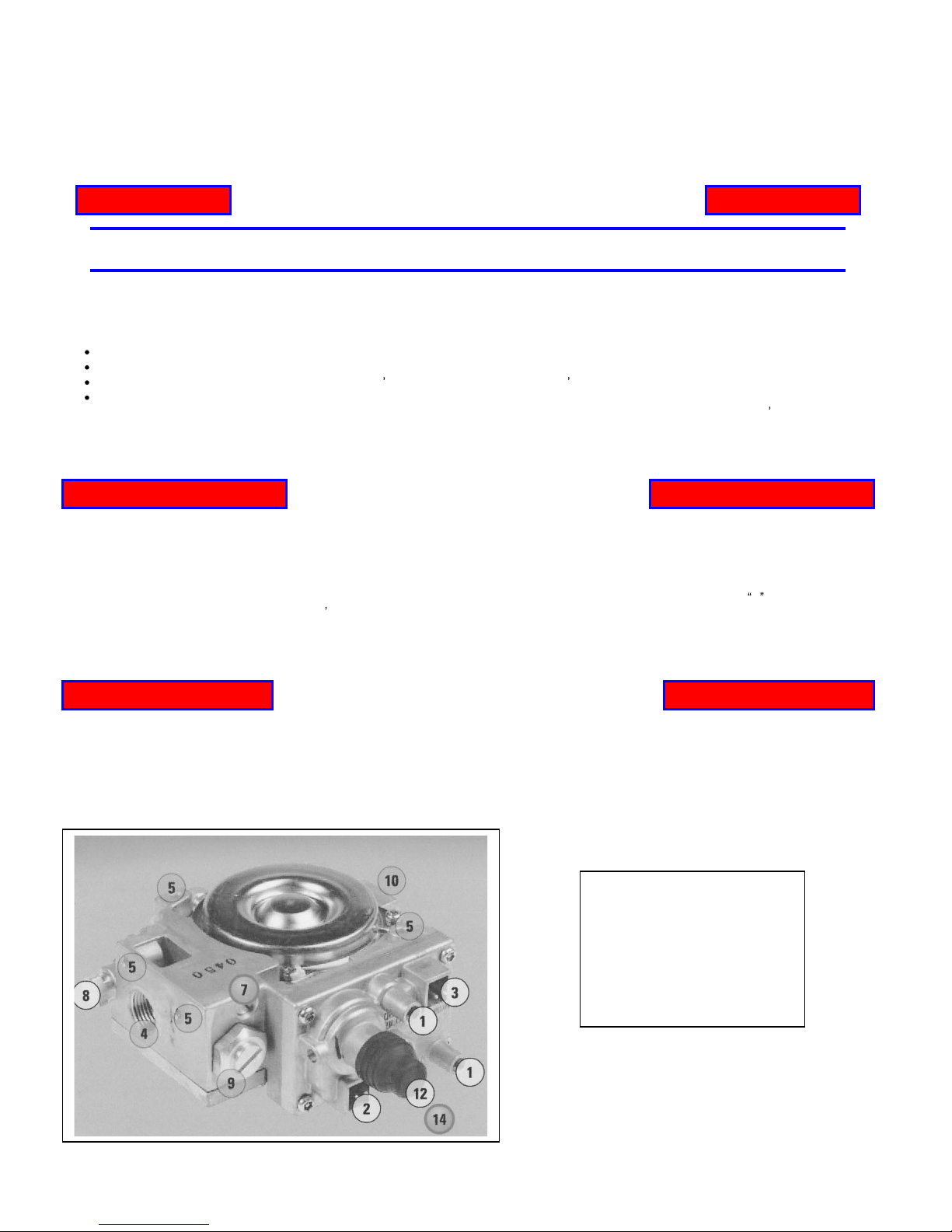
1. Pressure Taps
2. Main Valve Connection
3. Pi
lot Internal Solenoid Connection
4. Outlet Ports
5. Mounting Holes
7. Flow Control Screw
8. Pilot Connections
9. High/Low Connection
10. Inlet Ports
Page 14
of 54
2.1
INSTRUCTIONS D'ALLUMAGE - Pilote intermittent
POUR PLUS DE SÉCURITÉ, LIRE AVANT
D ALLUMER
AVERTISSEMENT: Quiconque ne respecte pas à la letter les instructions dans la présente notice ri
squé
de déclencher un incendie ou une explosion entraînant des dommages, des blessures ou la mort.
A. Cet appareil est équipé d'un dispositif d'allumage qui allume automatiquement le pilote. Ne pas tenter d'allumer le pilote à la main
.
B.
Avant d allumer la veilleuse, reniflez tout autour de l appareil pour dé
celeur une odeur de gaz.
Reniflez près du plancher, car certains gaz sont
plus lourds que l air et peuvent s accumuler au niveau du sol.
QUE FAIRE SI VOUS SENTEZ UNE ODEUR DE
GAZ:
Ne pas tenter d allumer d appareil.
Ne touchez à aucun interrupteur; ne pas vous server des telephones se trouvant dans le bâtiment.
Appelez immédiatement votre fournisseur de gaz depuis un voisin. Suivez les instructions du fournisseur.
Si vous ne po
uvez rejoinder le fournisseur, appelez le service des incendies.
C. Ne pousser ou tourner la manette d admission do gaz qu à la main. Ne jamais employer doutil à
cette fin.
Si la manette reste coincée, ne tentez
Pas de la réparer; appelez un techn
ician qualifié.
Quiconque tente de forcer la manette ou de la réparer peut provoquer une explosion ou un
incendie.
D. N utilisez pas cet appareil s il a été plunge dans l eau, meme partiellement. Faites inspecter l appareil par un technician qualifi
é e
t remplacez toute
partie du système de contrôle et toute commande qui ont
été plongés dans leau.
INSTRUCTIONS D ALLUMAGE
1. ARRÊTEZ!
Lisez les instructions de s
écurité sur la portion supérieure de cette
etiquette.
2.
Ré
glez le thermostat à la temperature la plus basse.
3.
Coupez l alimentation électrique de l appareil.
4. Ne tentez pas d'allumer le pilote à la main
.
5.
Attendre cinq (5) minutes** pour laisser échapper tout le gaz.
Reniflez tout autour d
e l appareil, y compris prè
s du plancher, pour d
éceler une
odeur de gaz, Si vous sentez une odeur de gaz, ARRÉTEZ!
Passez à létape B des instructions de sécurité sur la portion supérieure (à gauche) de cette etiquette. Sil ny a
pas dodeur de gaz, passez à létape suivante.
7.
Mettez l appareil sous tension.
8. Réglez le thermostat à la temperàture désirée.
9. Si l'appareil ne fonctionne pas, suivez les instructions "Pour couper le gaz à l'appareil" et appelez votre
technicien ou votre fournisseur de gaz
COMMENT COUPER L ADMISSION DE GAZ
L APPAREIL
1.Réglez le thermostat à la temperature la plus basse
2.
Activer / OFF sur OFF.
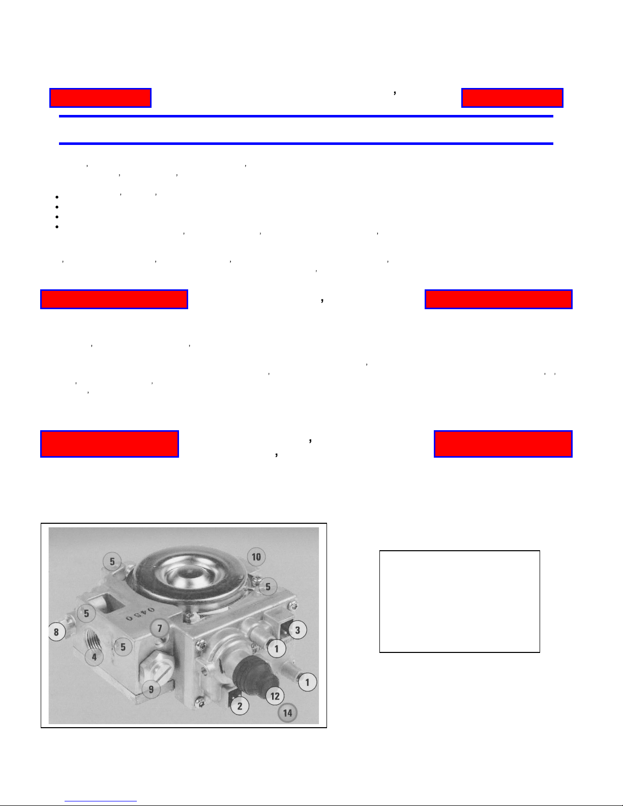
1.
Prises de pression
2.
Raccordement de la vanne principale
3.
Pilote de connexion interne solénoïde
4.
Ports de sortie
5.
Trous de montage
7.
Vis de réglage du débit
8.
Connexions pilote
9. High/Low Connection
10.
Ports d'entré
e
Page 15
of 54
3.0 INSTALLATION
3.1 INSTALLATION & SAFETY NOTES / NOTES D'INSTALLATION ET
DE SECURITE
Read all instructions before starting installation and follow them carefully during installation to ensure
maximum benefit and safety. Failure to follow these instructions will void your warranty and may
present a fire hazard. See the warranty at the back of this manual for disclaimers regarding improper
installation. This direct vent fireplace and it s components are tested and safe when installed in
accordance with this installation manual.
Lisez toutes les instructions avant de commencer l'installation et de les suivre attentivement lors de
l'installation pour assurer un bénéfice et une sécurité maximales. Le non respect de ces instructions
annule la garantie et peut présenter un risque d'incendie. Voir la garantie à l'arrière de ce manuel
pour décharges de responsabilité concernant une mauvaise installation. Ce foyer à évacuation
directe et ses composantes sont testés et sûrs lorsqu'il est installé conformément aux instructions de
montage.
WARNING
Do not connect 120 VAC to the gas control valve or it s components as this will
damage the valve.
Ne pas communiquer 120 VAC à la valve de contrôle du gaz ou de ses
composa
ntes, car cela endommagerait la vanne.
3.2 UNPACKING
Please check the appliance carefully for any damaged or missing components (specifically check the
glass condition). Report any problems to your dealer within 30 days of purchase.
3.3 INSTALLATION
For satisfactory results it is necessary to plan certain aspects of the installation prior to the
appliance s final positioning. These include the vent system, the gas piping, and the fans wiring.
Combustible surfaces such as the hearth, mantle, and facing must also be planned for. Be sure to
leave adequate clearance for servicing and proper operation.
Pour des résultats satisfaisants, il est nécessaire de planifier certains aspects de l'installation avant le
positionnement final de l'appareil. Il s'agit notamment du système de ventilation, les canalisations de
gaz, et le câblage fans. surfaces combustibles tels que le foyer, le manteau, et en face doivent
également être prévues pour. N'oubliez pas de laisser un espace suffisant pour l'entretien et bon
.
NOTE
ALL INSTALLATIONS REQUIRE VENTING.
Vented Gas Fireplace Not for Use with Solid Fuel
TOUTES LES INSTALLATIONS exigez l'aération.
Foyer au gaz à evacuation. Ne pas utiliser avec du combustible solide

Page 16
of 54
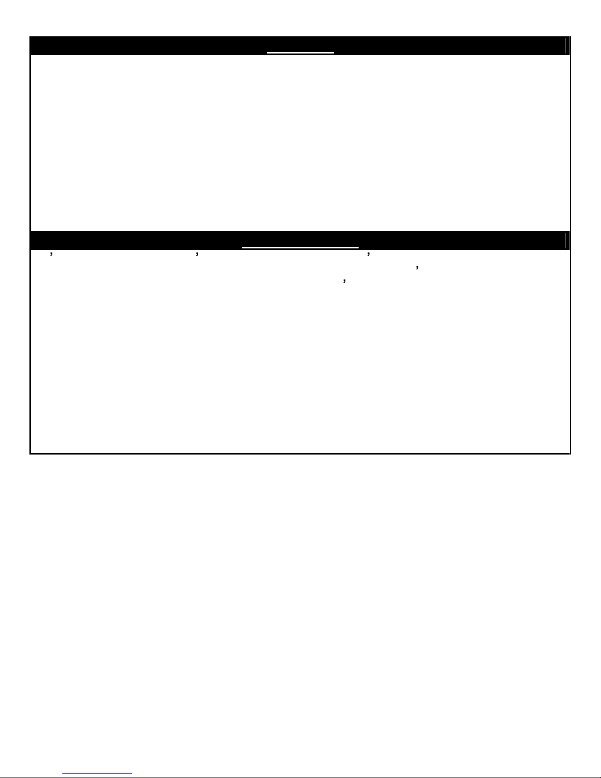
3.3.1 MINIMUM CLEARANCES
/
DÉGAGEMENTS
MINIMUM CLEARANCES TO COMBUSTIBLES
A = 58
TO INTERNAL CEILING
B = 4.5
TO INTERNAL SIDE COMBUSTIBLES
C = 19.5
TO BACK WALL FROM FRONT OF UNIT
D = 6
TO SIDE WALL
E = 39
FROM FLOOR TO COMBUSTIBLE MATERIAL
F=48
MINI
MUM CEILING HEIGHT FROM TOP OF UNIT
G=42
MINIMUM FROM FLOOR TO MANTLE (SEE DIAGRAM NEXT PAGE
H=0
BASE OF UNIT TO FLOOR
A
E
B
C
D
47.000
39.000
58.000
19.500
4.500
4.500
6.000
F
H
48
.000
0.000
Page 17
of 54
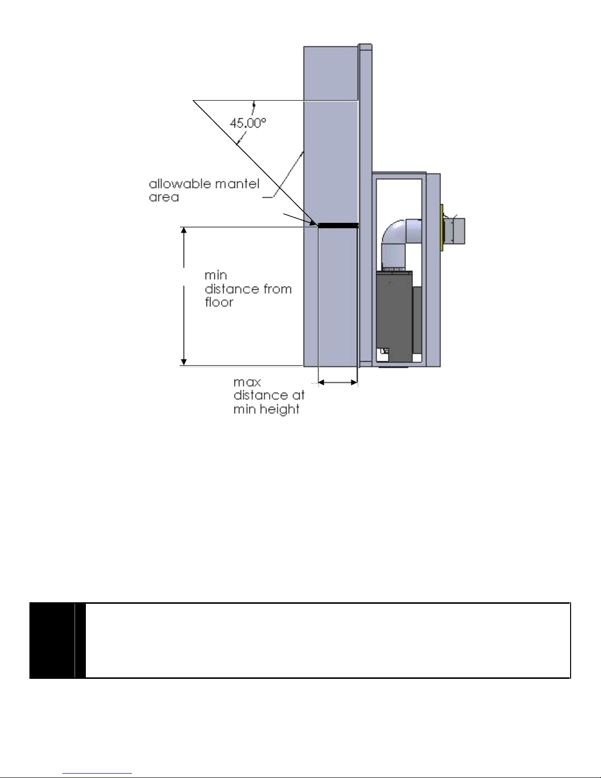
Clearances are in accordance with local installation codes and the requirements of the gas supplier.
**
The man
tel placement chart on this page illustrates the allowable mantel sizes and placements. The
45 degree angle can be used to determine the allowable mantel size based on the elevation above
the units upper trim.
Les dégagements sont en conformité avec les codes d'installation locaux et les exigences du
fournisseur de gaz.
** Le tableau placement manteau sur cette page illustre les dimensions et les emplacements
admissibles cheminée.
L'angle de 45 degrés peut être utilisé pour déterminer la taille permise
ma
nteau repose sur l'élévation au-dessus de la garniture unités supérieures.
CAU TION
ATTENTION
When using paint or lacquer to finish the mantel, such paint or lacquer must be heat
resistant ( up to 250o F ) to prevent discolorations.
Lors de l'utilisat
ion de peinture ou de laque à la fin de la cheminée, de peinture ou
laque doit être résistante à la chaleur (jusqu'à 250o F) pour prévenir la décoloration.
42.000
12.000
Mantle
 Loading...