

CLIENT # LC773211
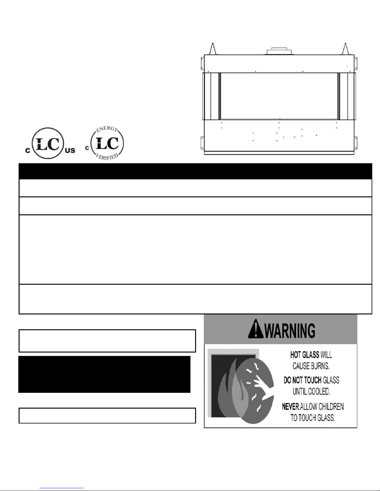
GALAXY SERIES PENINSULA FIREPLACE
WARNING
IF THE INFORMATION IN THESE INSTRUCTIONS IS NOT FOLLOWED EXACTLY, A FIRE OR
EXPLOSION MAY RESULT CAUSING PROPERTY DAMAGE, PERSONAL INJURY, OR DEATH.
Do not store or use gasoline or other flammable vapors and liquids in the vicinity of this or any
other appliance.
WHAT TO DO IF YOU SMELL GAS:
Do not try to light any appliance
Do not touch any electrical switch; do not use any phone in your building
Immediately call your gas supplier from a neighbour’s phone. Follow gas supplier’s
instructions
If you cannot reach your gas supplier, call the fire department.
Installation and service must be performed by a qualified installer, service agency or gas
supplier.
WARNING: Improper installation, adjustment, alteration, services or maintenance can cause
injury or property damage. Refer to this manual. For assistance or additional information consult
a qualified installer, service agency or the gas supplier.
INSTALLER: Leave this manual with the appliance.
CONSUMER: Retain this manual for future reference.
PLEASE READ THIS MANUAL BEFORE
INSTALLING OR USING THIS APPLIANCE.
SAVE THIS MANUAL FOR FUTURE
REFERENCE.
THIS FIREPLACE IS EQUIPPED WITH DOUBLE GLASS.
PLEASE READ IMPORTANT INFORMATION ON PAGE 4
36,000 BTU
Natural Gas & Propane
Installation and Operating Instructions
MODEL: GA-48
Page 1 of 55
CLIENT # LC773211
FOYER DE LA PÉNINSULE GALAXY SERIES
AVERTISSEMENT
ASSUREZ-VOUS DE BIEN SUIVRE LES INSTRUCTIONS DONNÉES DANS CETTE NOTICE POUR
RÉDUIRE AU MINIMUM LE RISQUE D'INCENDIE OU D'EXPLOSION OU POUR ÉVITER TOUT
DOMMAGE MATÉRIEL, TOUTE BLESSURE OU LA MORT.
Ne pas entreposer ni utiliser d'essence ni d'autres vapeurs ou liquids inflammables dans le
voisinage de cet appareil ou de tout autre appareil.
QUE FAIRE SI VOUS SENTEZ UNE ODEUR DE GAZ:
Ne pas tenter d'allumer d'appareil.
Ne touchez à aucun interrupteur. Ne pas vous servir des telephones se trouvant dans le
bâtiment où vous vous trouvez.
Appelez immédiatement votre fournisseur de gaz depuis un voisin. Suivez les instructions
du fournisseur.
Si vous ne pouvez rejoindre le fournisseur de gaz, appelez le service des incendies.
L'installation et l'entretien doivent être assurés par un installateur ou un service d'entretien
qualifié ou par le fournisseur de gaz.
AVERTISSEMENT: Une mauvaise installation, de réglage, la modification, de services ou de
maintenance peut causer des dommages corporels ou matériels. Reportez-vous à ce manuel.
Pour toute assistance ou information supplémentaire, consulter un installateur qualifié, un
service ou le fournisseur de gaz.
INSTALLATEUR : Laissez cette notice avec
l’appareil.
CONSOMMATEUR : Conservez cette notice pour
consultation ultérieure.
CE FOYER EST ÉQUIPÉ DE DOUBLE VERRE.
VEUILLEZ LIRE LES RENSEIGNEMENTS
IMPORTANTS À LA PAGE 4
S'IL VOUS PLAIT LIRE CE MANUEL AVANT
D'INSTALLER OU UTILISER CET
APPAREIL. CONSERVEZ CE MANUEL
POUR REFERENCE FUTURE.
AVERTISSEMENT
Une surface vitrée chaude
peut causer des brûlures.
Laisser refroidir la surface
vitrée avant d’y toucher
Ne permettez jamais à un
enfant de toucher la
surface vitrée.
36,000 BTU
Manuel D’installation et Guide de l’utilisateur
MODEL: GA-48
GAZ NATUREL ET PROPANE
Page 2 of 55

Table of Contents
IMPORTANT SAFETY INFORMATION ……………………………………………………………… 4-6
1.0 INTRODUCTION .....................................................................................................................
1.1 Specifications, Appliance Dimensions & Installation Codes ................................... 7-8
1.2 Features, Remote Control Functions .................................................................... 9-11
1.3 Intended Use ............................................................................................................ 12
1.4 General Safety .................................................................................................... 12-13
2.0 OPERATION ...........................................................................................................................
2.1 Lighting Instructions ........................................................................................... 14-15
3.0 INSTALLATION ......................................................................................................................
3.1 Installation & Safety Notes ...................................................................................... 16
3.2 Unpacking ................................................................................................................ 16
3.3 Installation ............................................................................................................... 16
3.3.1 Installation of Wiring ................................................................................................. 17
3.3.2 Minimum Clearances .......................................................................................... 18-21
3.3.3 Gas Line Installation ................................................................................................ 22
3.3.4 Direct Vent Information ...................................................................................... 23-34
3.3.5 Logs, Rocks & Glass Pebble Installation ............................................................ 35-37
3.3.6 Inner & Outer Glass Panel Removal & Installation ................................................... 38
3.3.7 Initial Firing .............................................................................................................. 39
3.3.8 Pilot Flame Adjustment ............................................................................................. 39
3.3.9 Primary Air Adjustment ...................................................................................... 39-40
3.3.10 Altitude Adjustment .................................................................................................. 40
3.3.11 Fan Access ......................................................................................................... 41-42
3.3.12 Gas Valve Access .................................................................................................... 42
4.0 MAINTENANCE .....................................................................................................................
4.1 Maintenance Safety ................................................................................................. 43
4.2 Recommended Service ........................................................................................... 43
4.3 Glass Cleaning ........................................................................................................ 44
4.4 Burner & Pilot Cleaning ........................................................................................... 44
4.5 Valve & Pilot Replacement ............................................................................... 44-45
5.0 TROUBLE SHOOTING ……………………………………………………………….…….. 45-46
6.0 REPLACEMENT PARTS ………………………………………………………………………...47
7.0 WARRANTY .…………………………………………………………………………………..48-50
8.0 LABEL INFORMATION .………………………………………………………………….…..51-52
APPENDIX A (INTERMITTENT PILOT & VALVE KIT)……………………....…………………...52-53
Page 3 of 55
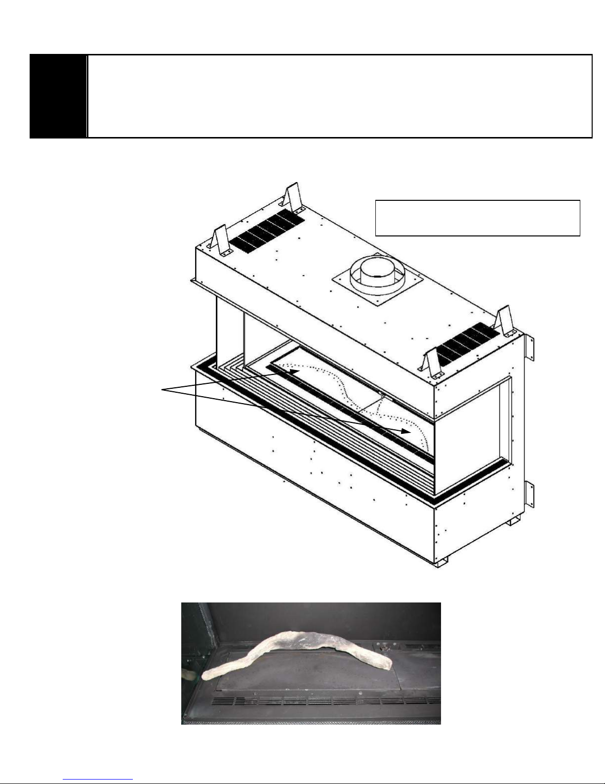
This fireplace is equipped with double glass. Air is constantly blown up between the glass from 3 fans in the base of the
WARNING
THE GLASS IN THIS UNIT IS FRAGILE. DO NOT CHIP OR KNOCK CORNER EDGES WHEN
REMOVING OR REPLACING AS THIS WILL CAUSE CRACKING WHICH IS NOT COVERED UNDER
WARRANTY.
THE EXTERNAL GLASS TEMPERATURE MAINTAINS THE LATEST REGULATORY STANDARD
OF LESS THAN 172°F FOR GLASS WITHOUT A MESH BARRIER
ATTENTION
LE VERRE DANS CETTE UNITÉ EST FRAGILE. NE PAS CHIPER OU GOMMER LES BORDS
D'ANGLE LORS DE L'ENLÈVEMENT OU DU REMPLACEMENT, CAR CELA PROVOQUERA UN
FISSURAGE QUI N'EST PAS COUVERT SOUS GARANTIE.
LA TEMPÉRATURE EXTÉRIEURE DU VERRE CONSTITUE LA DERNIÈRE NORME
RÉGLEMENTAIRE INFÉRIEURE À 172 ° F POUR LE VERRE SANS BARRIÈRE À MAILLE
UNE SURFACE VITREE CHAUDE PEUT
CAUSER DES BRULURES.
LAISSER REFROIDIR LA SURFACE
VITREE AVANT D’Y TOUCHER
NE PERMETTEZ JAMAIS A UN ENFANT
DE TOUCHER LA SURFACE VITREE.
fireplace. These fans must operate when the fireplace is in use. The fans will automatically come on after 6 minutes
once the fireplace is started up and they will go off 10 minutes after the fireplace is shut down.
There is a high limit thermodisc (see diagram on page 41) that will automatically shut the fireplace down if any of the
fans cease working and the fireplace overheats. If this happens then the fans need to be checked to make sure all 3
fans are still operational. If any of the fans are not working plug the fan in and test it. If any of the fans are faulty they will
need to be replaced. If the fans are working then the thermodisc needs to be checked. They should be closed up at
250° F. If the thermodisc is faulty it will need to be replaced before your fireplace will operate again.
When the fireplace is operating normally the external glass temperature is in complete compliance with the latest
regulatory standard maintaining temperatures of less than 172°F. Do not touch the glass it may cause burns.
Cette cheminée est équipée de double vitrage. L'air est constamment gonflé entre le verre de 3 ventilateurs dans la
base de la cheminée. Ces ventilateurs doivent fonctionner lorsque le foyer est utilisé. Les ventilateurs s'allumeront
automatiquement au bout de 6 minutes une fois le foyer démarré et ils s'éteindront 10 minutes après l'arrêt du foyer.
Il y a un thermodisque à limite haute (voir le diagramme à la page 41) qui éteindra automatiquement le foyer si l'un des
ventilateurs cesse de fonctionner et que le foyer surchauffe. Si cela se produit, les ventilateurs doivent être vérifiés pour
s'assurer que les trois ventilateurs sont toujours opérationnels. Si l'un des ventilateurs ne fonctionne pas, branchez le
ventilateur et testez-le. Si l'un des ventilateurs est défectueux, ils devront être remplacés. Si les ventilateurs
fonctionnent, le thermodisque doit être vérifié. Ils devraient être fermés à 250 ° F. Si le thermodisque est défectueux, il
devra être remplacé avant que votre foyer fonctionne à nouveau.Lorsque le foyer fonctionne normalement, la
température extérieure du verre est entièrement conforme aux normes réglementaires les plus récentes qui
maintiennent des températures inférieures à 172 ° F. Ne touchez pas le verre, cela pourrait causer des brûlures.
Page 4 of 55
WARNING
Read this owner’s manual carefully and completely before trying to assemble, operate or
service this fireplace. Follow instructions for proper installation
Failure to install this appliance per the manufacturer’s instructions or failure to use only
parts specifically approved with this appliance may result in property damage or personal
injury. Any change to this fireplace or its controls can be dangerous.
Improper installation or use of this fireplace can cause serious injury or death from fire,
burns, explosions, electrical shock and carbon monoxide poisoning.
AVERTISSEMENT
• Lisez ce manuel attentivement et complètement avant d'essayer de monter, utiliser ou
entretenir ce foyer. Suire les instructions pour assurer une bonne installation.
• Risque de dommages ou de blessures si l’appareil n’est pas installé selon les instructions
du fabricant ou si des pièces autres que celles spécifiquement approuvées avec cet appareil sont
utilisées. Tout changement à ce foyer ou à ses contrôles peuvent être dangereux.
• Une mauvaise installation ou l'utilisation de cette cheminée peut causer des blessures
graves ou la mort par le feu, les brûlures, explosions, de chocs électriques et intoxication au
monoxyde de carbone.
DUE TO HIGH TEMPERATURES, THE APPLIANCE SHOULD BE LOCATED OUT OF TRAFFIC AND AWAY FROM FURNITURE
AND DRAPERIES.
CHILDREN AND ADULTS SHOULD BE ALERTED TO THE HAZARDS OF HIGH SURFACE TEMPERATURE AND SHOULD STAY
AWAY TO AVOID BURNS OR CLOTHING IGNITION.
YOUNG CHILDREN SHOULD BE SUPERVISED WHEN THEY ARE IN THE SAME ROOM AS THE APPLIANCE.
CLOTHING OR OTHER FLAMMABLE MATERIAL SHOULD NOT BE PLACED ON OR NEAR THE APPLIANCE.
KEEP THE ROOM AREA CLEAR AND FREE FROM COMBUSTIBLE MATERIALS, GASOLINE, AND OTHER FLAMMABLE VAPORS
AND LIQUIDS.
EN RAISON DE TEMPERATURES ELEVEES, L'APPAREIL DOIT ETRE PLACE HORS DE LA CIRCULATION ET LOIN DES
MEUBLES ET TENTURES.
ENFANTS ET ADULTES DOIVENT ETRE AVERTIS DES DANGERS DE LA TEMPERATURE DE SURFACE ELEVEE ET DEVRAIT
RESTER A L'ECART POUR EVITER LES BRULURES OU L'INFLAMMATION DES VETEMENTS.
LES JEUNES ENFANTS DOIVENT ETRE SOIGNEUSEMENT SURVEILLES QUAND ILS SONT DANS LA MEME PIECE QUE
L'APPAREIL.
CLOTHING OR OTHER MATERIAUX COMBUSTIBLES NE DOIVENT PAS ETRE PLACES SUR OU PRES DE L'APPAREIL.
GARDER LA ZONE SALLE CLAIRE ET LIBRE DE MATERIAUX COMBUSTIBLES, D'ESSENCE, ET AUTRES VAPEURS ET
LIQUIDES
Page 5 of 55
WARNING
AVERTISSEMENT
Do not use this appliance if any part has
been under water. Immediately call a
qualified service technician to inspect the
appliance and to replace any part of the
control system and any gas control which
has been under water.
Ne pas utiliser cet appareil s’il a été plongé,
meme partiellement, dans l’eau. Appeler un
technician qualifié pour inspecter l’appareil et
remplacer toute partie du système de
commande et toute commande qui a été
plongée dans l’eau.
Toddlers, young children and others may be
susceptible to accidental contact burns. A
physical barrier is recommended if there are
at risk individuals in the house. To restrict
access to a fireplace or stove install an
adjustable safety gate to keep toddlers,
young children and at risk individuals out of
the room and away from hot surfaces.
Installation and repair should be done by a
qualified service person. The appliance
should be inspected before use and at least
annually by a professional service person.
More frequent cleaning may be required due
to excessive lint from carpeting, bedding
material, et cetera. It is imperative that
control compartments, burners and
circulating air passageways of the appliance
be kept clean.
Les tout-petits, les jeunes enfants et d'autres
peuvent être sensibles aux brûlures par
contact accidentel. Une barrière physique est
recommandé s'il ya des personnes à risque
dans la maison. Pour restreindre l'accès à une
cheminée ou un poêle installer une barrière de
sécurité réglable pour garder les tout-petits,
les jeunes enfants et les personnes à risque de
la salle et à l'écart des surfaces chaudes.
Installation et réparation doit être effectuée par
un technicien qualifié. L'appareil doit être
inspecté avant son utilisation et au moins
annuellement par un technicien qualifié. Un
nettoyage plus fréquent peut être nécessaire
en raison de peluches provenant des tapis,
literie, etc. Il est impératif que les
compartiments de contrôle, les brûleurs et les
conduits d'air de l'appareil soient gardés
propres.
This fireplace is a vented product. This
fireplace must be properly installed by a
qualified service person. The glass panels
must be properly seated and sealed. If this
unit is not properly installed by a qualified
service person with the glass door properly
seated and sealed gas leakage can occur.
Cette cheminée est un produit ventilé. Ce foyer
doit être correctement installé par un
technicien qualifié. Les panneaux de verre
doivent être correctement placés et scellés. Si
cette unité n'est pas correctement installée par
un technicien qualifié avec la porte vitrée
correctement installée et une fuite de gaz
scellée peut se produire.
Caution: Label all wires prior to
disconnection when servicing controls.
Wiring errors can cause improper and
dangerous operation.
Attention : Au moment de l’entretien des
commandes, étiquetez tous les fils avant de
les débrancher. Des erreurs de câblage
peuvent entraîner un fonctionnement
inadéquate et dangereux.
Verify proper operation after servicing
S’assurer que l’appareil fonctionne
adéquatement une fois l’entretien terminé
If appliance is installed directly on carpeting,
vinyl tile or other combustible material other
than wood flooring, the appliance shall be
installed on a metal or wood panel extending
the full width and depth of the fireplace.
Si l'appareil est installé directement sur un
tapis, carreaux de vinyle ou autre matériau
combustible autre qu'un plancher de bois,
l'appareil doit être installé sur un panneau de
métal ou de bois se prolongeant sur toute la
largeur et la profondeur de la cheminée.
Page 6 of 55
ITEM
NATURAL GAS (NG)
PROPANE (LP)
MAXIMUM INPUT: Hi
36,000 Btu/hr (10.55 kW)
28,500 Btu/hr (8.35 kW)
MINIMUM INPUT: Lo
21,000 Btu/hr (6.15 kW)
21,500 Btu/hr (6.30 kW)
MANIFOLD PRESSURE:
COLLECTEUR DE PRESSION:
3.5” w.c. (0.87 kPa)
10.0” w.c. (2.49 kPa)
GAS INLET SUPPLY PRESSURE:
ENTREE DE PRESSION
Minimum: 5.0” w.c. (1.2 kPa)
Minimum: 7.0” w.c. (1.74 kPa)
Maximum: 10.5” w.c. (2.61 kPa)
Maximum: 13.0” w.c. (3.23 kPa)
ORIFICE SIZE: @ 0-4500’
FORMAT D'ORIFICE:
2 X # 48 DMS
2 X # 56 DMS
AIR SHUTTER
VOLET DE L’AIR
OPEN 1/4”min
(6.35mm)
FULLY OPEN
CONTROL VALVE TYPE:
TYPE DE SOUPAPE
Skytech AF-40004
Skytech AF-40004
VENTING
ÉVACUATION
2-ply aluminum vent, Selkirk,
Duravent , Security Venting,
ICC Venting or
Metal-Fab Venting
2-ply aluminum vent, Selkirk
Duravent, Security Venting,
ICC Venting or
Metal-Fab Venting
FANS
VENTILATEUR
4 pcs Variable Speed (110 Volt / 60 Hz)
4 pcs Variable Speed (110 Volt / 60 Hz)
THIS APPLIANCE IS ONLY FOR USE WITH THE TYPE OF GAS INDICATED ON THE RATING
PLATE.
CET APPAREIL DOIT ÊTRE UTILISÉ UNIQUEMENT AVEC LE TYPE DE GAZ INDIQUÉ SUR LA
PLAQUE SIGNALÉTIQUE.
1.0 INTRODUCTION
1.1 SPECIFICATIONS
TABLE 1
Page 7 of 55
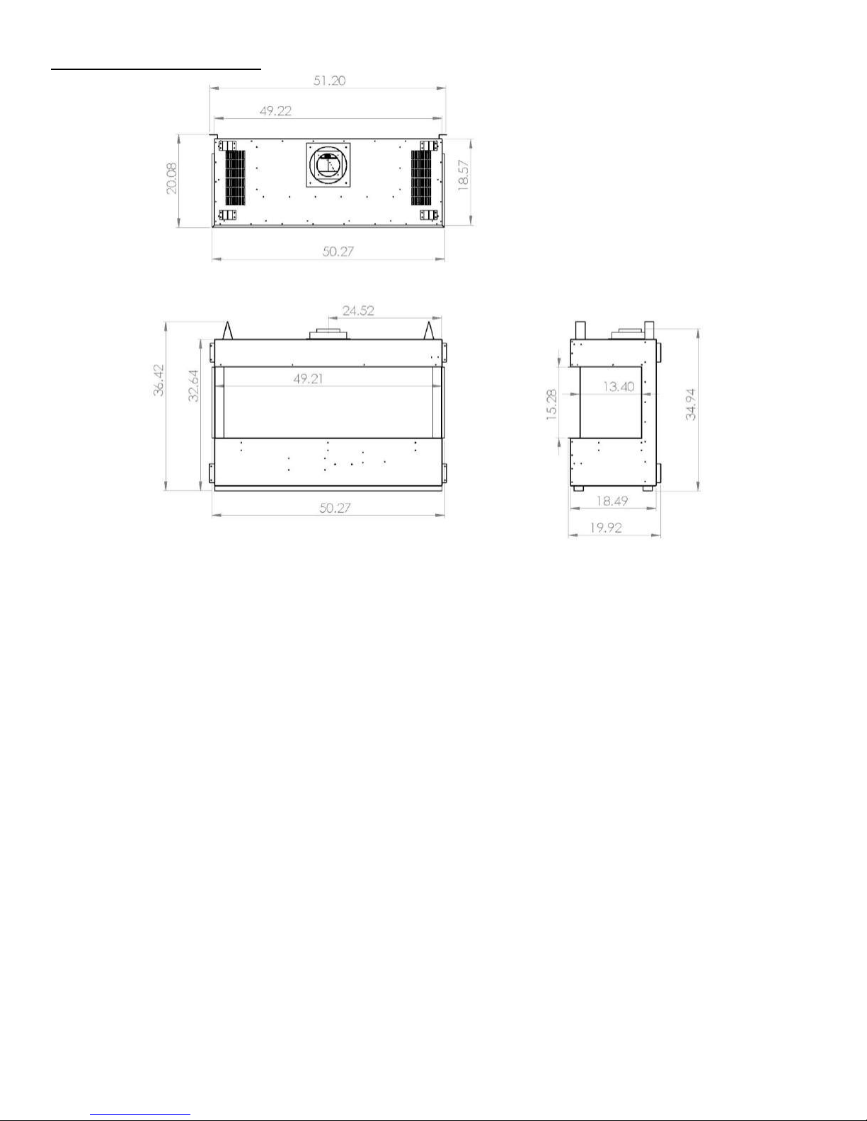
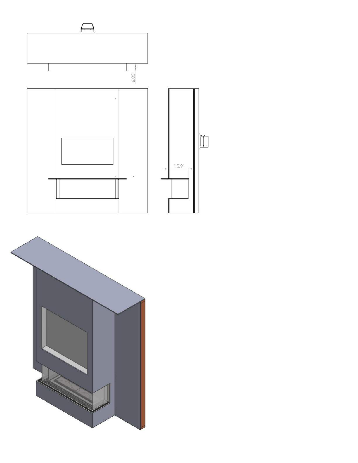
APPLIANCE DIMENSIONS
INSTALLATION CODES
This appliance is a Direct Vent appliance which draws all combustion air from outside the building
through an intake vent pipe.
Installation must conform to local codes. In the absence of local codes, installation must conform to the
National Fuel Gas Code ANSI Z223.1/NFPA 54, or the current Natural Gas and Propane Installation
Code CSA B149.1. The unit, when installed, must be electrically grounded in accordance with local
codes or, in the absence of local codes, with the National Electric Code ANSI/NFPA No.70 or with the
current Canadian Electrical Code CSA C22.1. In the state of Massachusetts, this product can only be
installed by a licensed plumber or a licensed gas fitter. Failure to comply will void the warranty.
This appliance has been certified for use with natural gas and propane.
This appliance is not for use with solid fuels.
CODES D'INSTALLATION
Cet appareil est un appareil à évent direct, qui attire tous l'air de combustion provenant de l'extérieur du
bâtiment par une entrée d'évent.
L'installation doit se conformer aux codes locaux. En l'absence de codes locaux, l'installation doit être
conforme au National Fuel Gas Code ANSI Z223.1/NFPA 54, ou le gaz naturel actuel et le Code
d'installation du propane CSA B149.1. L'unité, une fois installé, doit être électriquement à la terre
conformément aux codes locaux ou, en l'absence de codes locaux, avec le National Electric Code ANSI /
NFPA No.70 ou avec l'actuel Code canadien de l'électricité CSA C22.1
Cet appareil a été certifié pour une utilisation avec du gaz naturel et le propane.
Cet appareil n'est pas pour une utilisation avec des combustibles solides.
Page 8 of 55
1.2 FEATURES
Ignition system:
Electronic pilot ignition system with thermopile and thermocouple flame detection.
Gas control: * Optional*
Gas control valve type:
Automatic millivolt powered combination gas control valve with variable flame control for
convenience and on/off switch. Optional digital remote on/off wall switch and/or optional wall
thermostat (note: thermostats are not allowed in the United States). The gas valve does not
require electricity from an external source.
Electronic Valve:
Automatic DC valve with AC power adapter. Hand held remote control.
Fan control:
Variable speed control:
For units equipped with a fan control, adjust speed by remote control settings 1-6. There are 3
fans in this unit controlled by a Hi/Low Thermodisc.
The fans cannot be shut off manually.
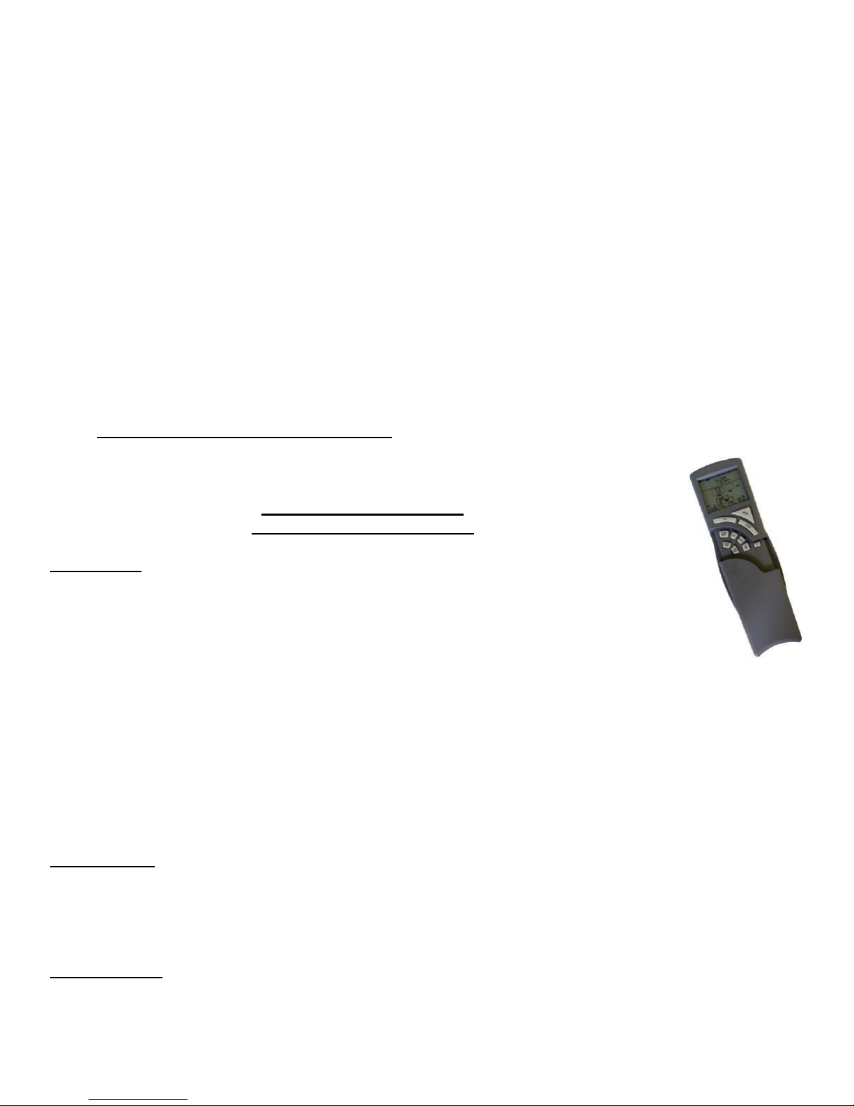
Supreme Remote Control
Functional Operation Matrix
Initial Setup
Installation of (2) AAA-size batteries will activate the setup mode. Setup mode can
also be activated by pressing the FLAME REAR and PROG/TIME buttons
simultaneously for 5 seconds. The control will exit setup mode if no button is pressed
for 20 seconds. Appropriate icon on LCD will flash when ready for setup.
Press the UP or Down button in setup mode to change the temperature scale. Press SET button to skip or
advance to Fuel Type setup.
Press the UP or DOWN button to switch control from Natural to LP, or LP to Natural Gas. Press SET button
to skip or advance to Clock setup.
Press the UP or Down Button to set the hour. Press SET to advance to minutes.
Press the UP or Down button to set minutes. Press SET to advance to AM or PM.
Press the UP or Down button to set AM or PM. Press the SET button to advance to the day of week.
Use UP or Down button to select the day of the week.
The control will exit setup mode in 20 seconds.
MODE Button
The MODE button cycles the unit through the basic operational modes.
When off, press and release the MODE button to turn the unit on in Manual mode.
Press and release the MODE button again, and the unit will operate in the Thermostat mode.
Press and release the MODE button again, and the unit will turn off.
Program Mode
The Program function is controlled by the PROG/TIME button. The control may be programmed for up to two
settings for weekdays and two settings for weekends. The control is preset to factory settings.
Page 9 of 55

When the Program Mode is activated, the unit will automatically be operating in the Thermostat Mode. The
unit will turn on or off based upon room and set temperature.
To activate the Program mode, press and release the PROG/TIME button.
To change the settings for the Program mode, press and hold the PROG/TIME button for 5 seconds. The
program feature will flash at the top of the screen.
Press the UP or DOWN button to change the setting of the weekday (MTWTF) P1 ON. Press and release the
SET button.
Press the UP or DOWN button to change the setting of P1 OFF. Press and release the SET button.
Press the UP or DOWN button to change the setting of P2 ON. Press and release the SET button.
Press the UP or DOWN button to change the setting of P2 OFF. Press and release the SET button.
Press the UP or DOWN button to change the setting of the weekend (SS) P1 ON. Press and release the
SET button.
Press the UP or DOWN button to change the setting of P1 OFF. Press and release the SET button.
Press the UP or DOWN button to change the setting of P2 ON. Press and release the SET button.
Press the UP or DOWN button to change the setting of P2 OFF. Press and release the SET button.
The Program Mode has been re-programmed.
Countdown Timer
The Countdown Timer Mode allows the control to operate the unit for up to 3 hours, in 10-minute increments.
It can be operated in either the Manual or Thermostat Modes.
To enter Timer Mode, press and release the TIMER button. The Timer icon will flash.
Press the UP or DOWN button to set the running time, in 10-minute increments. Press and release the SET
button. The timer will run for the set time duration.
Pressing the TIMER button while in Timer Mode will terminate the Timer operation. The Timer operation will
also terminate if the MODE button is cycled to off.
Thermostat Mode
The unit is placed in Thermostat Mode using the MODE button. Placing the unit in Thermostat Mode will
activate the numbers in the smaller window on the LCD screen.
Press the UP or DOWN button to change the thermostat set temperature. When the desired set temperature
appears, press and release the SET button to set.
If the SET button is not pressed, the set temperature will automatically be set after 5 seconds.
The Thermostat Mode can be de-activated by pressing the MODE button.
Thermostatic Flame Modulation
This control can perform Main Flame Modulation using the Thermostat. The control will shut the unit off when
the room temperature reaches 2 above set temperature. The Thermostat will automatically modulate the
main flame:
Manual Flame Modulation – Main Flame
To change the Flame Level manually, press the FLAME MAIN button. The current level will show in the
MAIN box on the LCD screen.
Press the UP or DOWN button to change the Flame Level.
When the unit is turned on, whether in Manual, Thermostatic, or Program Mode, the Main Flame will
automatically ignite at the High (7) setting. After 5 seconds, the flame will default to the previous setting.
Page 10 of 55

Fan Control
The unit must be ON to operate the Fan.
The Fan will turn on after 6 minutes of operation. Once the Fan comes on, it can be controlled using the FAN
button.
Press the FAN button, and the fan icon and speed will appear on the LCD screen.
Press the UP or DOWN button to control the fan speed (1-6).
The fan will run for 10 minutes after the unit is shut off in any mode. The fan may not be controlled during this
period nor can it be turned off manually at any time while the fireplace is hot.
Continuous Pilot
The unit can be changed from Intermittent Pilot Ignition (IPI), to Continuous, or standing, pilot.
To place the unit in continuous pilot mode, press and release the PROG/TIME and the FLAME MAIN buttons
simultaneously. Continuous Pilot will appear on the LCD screen.
Repeat the simultaneous PROG/TIME and FLAME MAIN push to place the unit back in IPI mode.
This feature can also be activated by the Continuous Pilot (On/Off) switch on the Main Module.
Child Lock-Out
The Child Lock-out feature can be activated by pressing the PROG/Time and UP buttons simultaneously. CP
will appear on the LCD screen, and no signals can be sent from the transmitter.
To take the control out of Child Lock-out mode, repeat the above step. CP will disappear from the screen.
Learn Function
To program the system to a transmitter, press the LEARN button on the Main Module. A single audible beep
will be heard.
Press the MODE button on the transmitter to learn the transmitter to the system. A series of beeps will be
heard.
Up to two additional (NON-THERMOSTATIC) transmitters can be used simultaneously. To learn additional
transmitters, press and release the learn button again, and press the on button on the additional transmitters.
To clear all transmitters and start over, press and hold the LEARN button for 10 seconds. A series of three
beeps will be heard, and the system is clear.
Low Battery Indicator
A low battery icon will appear on LCD screen when transmitter batteries reach low voltage level.
Thermal Safety
When the internal components of the Main Module reach 170F, the unit will automatically shut off, and send
a repetitive audible signal. The unit can be turned back on when the module cools below 160
Communication Safety
When in the Thermostat or Program Mode, the transmitter will send a silent signal to the module every 15
minutes. If a signal is not received within 2 hours due to dead batteries, lost transmitter, or transmitter out of
range, the unit will automatically shut down, and the module will send a repetitive audible signal.
Page 11 of 55

1.3 INTENDED USE / USAGE PROPOSÉ
This appliance is intended to be used as a zero clearance fireplace.
Cet appareil est destiné à être utilisé comme un foyer à dégagement zéro.
1.4 GENERAL SAFETY / SÉCURITÉ GÉNÉRALE
Maintain adequate clearances around air openings into the combustion chamber.
Respecter les distances minimales convenables autour des bouches d'air dans la chambre de combustion.
Maintain adequate accessibility clearances for servicing and proper operation.
Respecter les distances minimales d'accessibilité suffisante pour l'entretien et bon.
This appliance shall not be connected to chimney flue serving a separate solid-fuel burning appliance.
Cet appareil ne doit pas être raccordé à une cheminée desservant un autre appareil brûlant des combustibles solides.
The appliance area must be kept clear and free from combustible materials, gasoline and other flammable liquids and
vapors.
La zone appareil doit rester clair et exempt de matériaux combustibles, essence et autres vapeurs et liquides
inflammables.
The flow of combustion and ventilation air shall not be obstructed.
Le débit de combustion et de ventilation ne doit pas être obstrué.
The combustion air supply shall be in the same pressure zone as the drafthood relief opening on an appliance
equipped with a drafthood or as the vent outlet on an appliance not equipped with a drafthood.
L'alimentation en air de combustion doit être dans la zone même pression que l'ouverture de secours hotte à air sur
un appareil équipé d'une hotte à air ou que l'évent de sortie sur un appareil n'est pas équipé d'une hotte à air.
Do not use this appliance if any part has been under water. Immediately call a qualified service technician to inspect
the appliance and to replace any part of the control system and any gas control which has been under water.
Ne pas se servir de cet appareil s’il a été plongé dans l’eau, même partiellement. Faire inspecter l’appareil par un
technicien qualifié et remplacer toute partie du système de contrôle et toute commande qui ont été plongées dans
l’eau.
Page 12 of 55
IMPORTANT
PLEASE READ THE FOLLOWING CAREFULLY
It is normal for fireplaces fabricated of steel to give off some expansion and/or contraction noises
during the start up or cool down cycle.
It is not unusual for gas fireplaces to give off some odors the first time they are burned. This is due to
the oils and sealants in the manufacturing process.
PLEASE ENSURE YOU ROOM IS WELL VENTILATED DURING BURN OFF – OPEN ALL WINDOWS
It is recommended that you burn your fireplace for at least 4 (four) hours the first time you use it.
IMPORTANT
S'IL VOUS PLAÎT LIRE ATTENTIVEMENT CE QUI SUIT
Il est normal pour les foyers fabriqués d'acier à dégager une certaine expansion et / ou des bruits de
contraction pendant le démarrage ou cycle de refroidissement.
Il n'est pas inhabituel pour les foyers à gaz de dégager certaines odeurs la première fois qu'ils sont
brûlés. Cela est dû aux huiles et produits d'étanchéité dans le processus de fabrication.
S'IL VOUS PLAÎT VOUS ASSURER pièce est bien aérée pendant BRÛLER - Ouvrir toutes les fenêtres
Il est recommandé que vous brûlez votre foyer pendant au moins 4 (quatre) heures la première fois
que vous l'utilisez.
WARNING
Hot while in operation. Do Not Touch. Severe burns may result. Keep children, clothing,
furniture, gasoline and other liquids having flammable vapors away.
Toddlers, young children and others may be susceptible to accidental contact burns. A
physical barrier is recommended if there are at risk individuals in the house. To restrict
access to a fireplace or stove install an adjustable safety gate to keep toddlers , young
children and at risk individuals out of the room and away from hot surfaces.
Installation and repair should be done by a qualified service person. The appliance should be
inspected before use and at least annually by a professional service person. More frequent
cleaning may be required due to excessive lint from carpeting, bedding material, et cetera. It is
imperative that control compartments, burners and circulating air passageways of the
appliance be kept clean.
AVERTISSEMENT
L’appareil est chaud lorsqu’il fonctionne. Ne pas toucher l’appareil. Risque de brûlures graves.
Surveiller les enfants. Garder les vêtements, les meubles, l’essence ou autres liquides
produisant des vapeur inflammables loin de l’appareil.
Les tout-petits, les jeunes enfants et d'autres peuvent être sensibles aux brûlures par contact
accidentel. Une barrière physique est recommandé s'il ya des personnes à risque dans la
maison. Pour restreindre l'accès à une cheminée ou un poêle installer une barrière de sécurité
réglable pour garder les tout-petits, les jeunes enfants et les personnes à risque de la salle et à
l'écart des surfaces chaudes.
Installation et réparation doit être effectuée par un technicien qualifié. L'appareil doit être
inspecté avant son utilisation et au moins annuellement par un technicien qualifié. Un
nettoyage plus fréquent peut être nécessaire en raison de peluches provenant des tapis, literie,
etc. Il est impératif que les compartiments de contrôle, les brûleurs et les conduits d'air de
l'appareil soient gardés propres.
Page 13 of 55
2.0 OPERATION
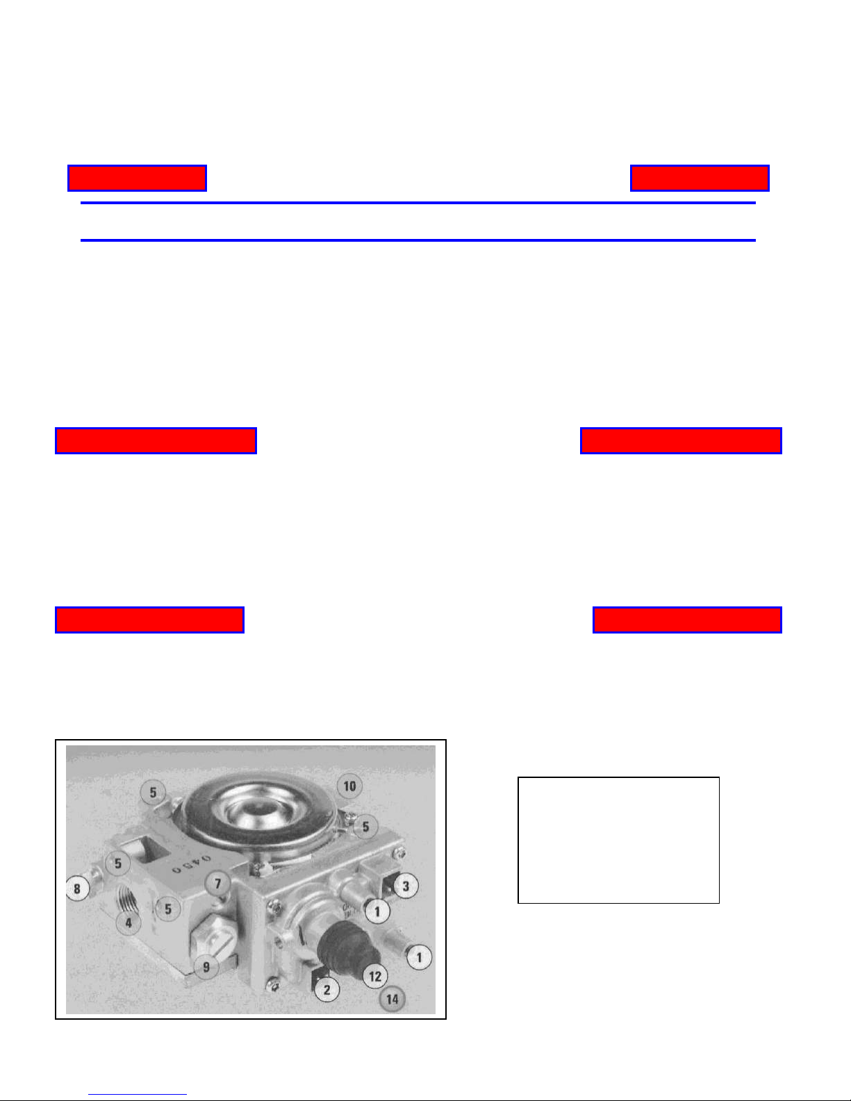
1. Pressure Taps
2. Main Valve Connection
3. Pilot Internal Solenoid Connection
4. Outlet Ports
5. Mounting Holes
7. Flow Control Screw
8. Pilot Connections
9. High/Low Connection
10. Inlet Ports
2.1 LIGHTING INSTRUCTIONS - for Intermittent Pilot
FOR YOUR SAFETY, READ BEFORE LIGHTING
WARNING: If you do not follow these instructions exactly, a fire or explosion may result causing property damage,
personal injury or loss of life.
A. This appliance is equipped with an ignition device which automatically lights the pilot. Do not try to light the pilot by hand.
B. BEFORE LIGHTING smell all around the appliance area for gas. Be sure to smell next to the floor because some gas is heavier than air and will settle
on the floor.
WHAT TO DO IF YOU SMELL GAS
Do not try to light any appliance.
Do not touch any electric switch; do not use any phone in your building.
Immediately call your gas supplier from a neighbour’s phone. Follow the gas supplier’s instructions.
If you cannot reach your gas supplier, call the fire department.
C. Use only your hand to push in or turn the gas control knob. Never use tools. If the knob will not push in or turn by hand, don’t try to repair it, call a
qualified service technician. Force or attempted repair may result in a fire or explosion.
D. Do not use this appliance if any part has been under water. Immediately call a qualified service technician to inspect the appliance and to replace any
part of the control system and any gas control which has been under water.
LIGHTING INSTRUCTIONS
1. STOP! Read the safety information above on this label.
2. Set the thermostat to the lowest setting.
3. Turn off all electric power to the appliance.
4. Do not attempt to light the pilot by hand.
5. Wait five (5) minutes to clear out any gas. Then smell for gas, including near the floor. If you smell gas, STOP! Follow “B” in the safety information
above on this label. If you don’t smell gas, go to the next step.
6. Turn on all electric power to the appliance.
7. Set thermostat to desired setting (or switch to "ON" if not using a thermostat).
8. If the appliance will not operate, follow the instructions "To Turn Off Gas To Appliance" and call your service technician or gas supplier.
TO TURN GAS OFF TO APPLIANCE
1.Set thermostat to lowest setting.
2.Turn on/off switch to off.
Page 14 of 55
2.1 INSTRUCTIONS D'ALLUMAGE - Pilote intermittent
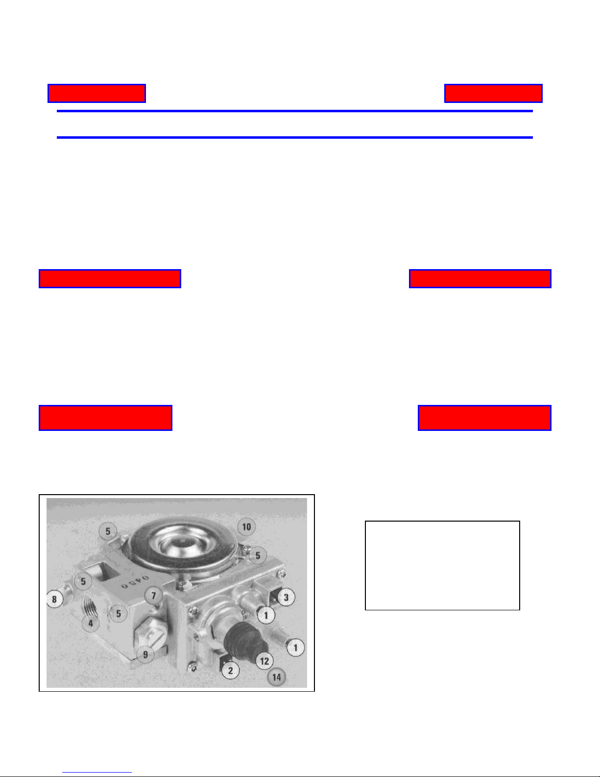
1. Prises de pression
2. Raccordement de la vanne principale
3. Pilote de connexion interne solénoïde
4. Ports de sortie
5. Trous de montage
7. Vis de réglage du débit
8. Connexions pilote
9. High/Low Connection
10. Ports d'entrée
POUR PLUS DE SÉCURITÉ, LIRE AVANT D’ALLUMER
AVERTISSEMENT: Quiconque ne respecte pas à la letter les instructions dans la présente notice risqué
de déclencher un incendie ou une explosion entraînant des dommages, des blessures ou la mort.
A. Cet appareil est équipé d'un dispositif d'allumage qui allume automatiquement le pilote. Ne pas tenter d'allumer le pilote à la main.
B. Avant d’allumer la veilleuse, reniflez tout autour de l’appareil pour déceleur une odeur de gaz. Reniflez près du plancher, car certains gaz sont
plus lourds que l’air et peuvent s’accumuler au niveau du sol.
QUE FAIRE SI VOUS SENTEZ UNE ODEUR DE GAZ:
Ne pas tenter d’allumer d’appareil.
Ne touchez à aucun interrupteur; ne pas vous server des telephones se trouvant dans le bâtiment.
Appelez immédiatement votre fournisseur de gaz depuis un voisin. Suivez les instructions du fournisseur.
Si vous ne pouvez rejoinder le fournisseur, appelez le service des incendies.
C. Ne pousser ou tourner la manette d’admission do gaz qu’à la main. Ne jamais employer d’outil à cette fin. Si la manette reste coincée, ne tentez
Pas de la réparer; appelez un technician qualifié. Quiconque tente de forcer la manette ou de la réparer peut provoquer une explosion ou un incendie.
D. N’utilisez pas cet appareil s’il a été plunge dans l’eau, meme partiellement. Faites inspecter l’appareil par un technician qualifié et remplacez toute
partie du système de contrôle et toute commande qui ont été plongés dans l’eau.
INSTRUCTIONS D’ALLUMAGE
1. ARRÊTEZ! Lisez les instructions de sécurité sur la portion supérieure de cette etiquette.
2. Réglez le thermostat à la temperature la plus basse.
3. Coupez l’alimentation électrique de l’appareil.
4. Ne tentez pas d'allumer le pilote à la main.
5. Attendre cinq (5) minutes** pour laisser échapper tout le gaz. Reniflez tout autour de l’appareil, y compris près du plancher, pour déceler une
odeur de gaz, Si vous sentez une odeur de gaz, ARRÉTEZ! Passez à l’étape B des instructions de sécurité sur la portion supérieure (à gauche) de cette etiquette. S’il n’y a
pas d’odeur de gaz, passez à l’étape suivante.
7. Mettez l’appareil sous tension.
8. Réglez le thermostat à la temperàture désirée.
9. Si l'appareil ne fonctionne pas, suivez les instructions "Pour couper le gaz à l'appareil" et appelez votre technicien ou votre fournisseur de gaz
COMMENT COUPER L’ADMISSION DE GAZ
L’APPAREIL
1.Réglez le thermostat à la temperature la plus basse
2.Activer / OFF sur OFF.
Page 15 of 55
3.0 INSTALLATION
WARNING
Do not connect 120 VAC to the gas control valve or it’s components as this will
damage the valve.
Ne pas communiquer 120 VAC à la valve de contrôle du gaz ou de ses composantes,
car cela endommagerait la vanne.
NOTE
ALL INSTALLATIONS REQUIRE VENTING.
Vented Gas Fireplace Not for Use with Solid Fuel
TOUTES LES INSTALLATIONS exigez l'aération.
Foyer au gaz à evacuation. Ne pas utiliser avec du combustible solide
3.1 INSTALLATION & SAFETY NOTES / NOTES D'INSTALLATION ET DE
SECURITE
Read all instructions before starting installation and follow them carefully during installation to ensure
maximum benefit and safety. Failure to follow these instructions will void your warranty and may present
a fire hazard. See the warranty at the back of this manual for disclaimers regarding improper installation.
This direct vent fireplace and it’s components are tested and safe when installed in accordance with this
installation manual.
Lisez toutes les instructions avant de commencer l'installation et de les suivre attentivement lors de
l'installation pour assurer un bénéfice et une sécurité maximales. Le non respect de ces instructions
annule la garantie et peut présenter un risque d'incendie. Voir la garantie à l'arrière de ce manuel pour
décharges de responsabilité concernant une mauvaise installation. Ce foyer à évacuation directe et ses
composantes sont testés et sûrs lorsqu'il est installé conformément aux instructions de montage.
3.2 UNPACKING
Please check the appliance carefully for any damaged or missing components (specifically check the
glass condition). Report any problems to your dealer within 30 days of purchase.
3.3 INSTALLATION
For satisfactory results it is necessary to plan certain aspects of the installation prior to the appliance’s
final positioning. These include the vent system, the gas piping, and the wiring. Combustible surfaces
such as the hearth, mantle, and facing must also be planned for. Be sure to leave adequate clearance
for servicing and proper operation.
Pour des résultats satisfaisants, il est nécessaire de planifier certains aspects de l'installation avant le
positionnement final de l'appareil. Il s'agit notamment du système de ventilation, les canalisations de gaz,
et le câblage. Surfaces combustibles tels que le foyer, le manteau, et en face doivent également être
prévues pour. N'oubliez pas de laisser un espace suffisant pour l'entretien et bon.
Page 16 of 55
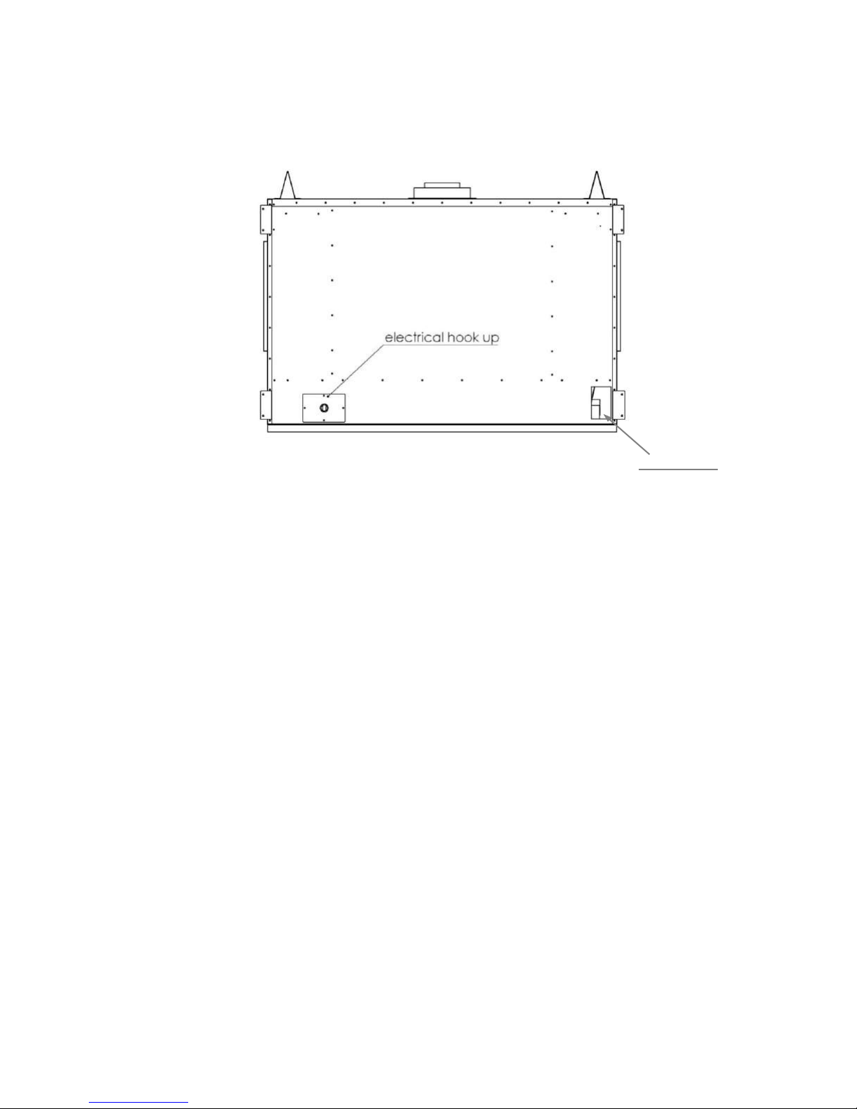
3.3.1 INSTALLATION OF WIRING
gas hook up
Before installing the fireplace it is critical that your electrician installs wiring for the electrical components
to operate. There is an opening in the rear left for the wires to be run through, (see diagram below), for
connection in the bottom of the firebox.
VIEWED FROM REAR OF FIREPLACE.
IMPORTANT:
MAKE SURE EVERYTHING IS PLUGGED IN BEFORE TURNING
ANYTHING ON.
IF ANY COMPONENTS ARE PLUGGED IN AFTER FIRING UP THE
FIREPLACE YOU MAY BLOW THE FUSES IN THE CONTROL SYSTEMS.
Page 17 of 55

3.3.2 MINIMUM CLEARANCES / DÉGAGEMENTS
A = 24”
MAXIMUM ALLOWABLE HEIGHT FROM FLOOR TO BOTTOM OF FIREPLACE
IF BUILDING UP OFF THE FLOOR ON A PLATFORM
B = 1”
TO INTERNAL BACK COMBUSTIBLES
C = 19.57”
TO BACK WALL FROM FRONT OF UNIT
D = 18”
FROM EDGE OF FIREPLACE TO SIDE WALL
E = 36.52”
FROM BOTTOM OF FIREPLACE TO STUD
F = 1”
TO INTERNAL SIDE COMBUSTIBLES
G=26.71”
MINIMUM FROM BOTTOM OF FIREPLACE TO MANTLE
(SEE DIAGRAMS NEXT PAGES)
H = 0”
11.34” FROM BASE OF SUPPORT CHANNELS AT BOTTOM OF UNIT
I = 72”
INTERNAL CEILING HEIGHT MINIMUM FROM BASE OF UNIT
A
B
C
D
E F G
F
24.00
36.52
H
I
THERE CAN BE NO WEIGHT BEARING ONTO THE FIREPLACE.
ALL CONSTRUCTION ABOVE THE FIREPLACE MUST BE SELF SUPPORTING.
NO DRYWALL SCREWS INTO THE METAL OF THE FIREPLACE.
USE A HIGH TEMPERATURE SILICONE TO ADHERE TO THE METAL
FRAMING DIMENSIONS : 51.25’’ W x 36.5’’ H x 19.5’’ D
MINIMUM CLEARANCES TO COMBUSTIBLES
Page 18 of 55

CAU
TION
ATTENTION
When using paint or lacquer to finish the mantel, such paint or lacquer must be heat
resistant ( up to 250o F ) to prevent discolorations.
Lors de l'utilisation de peinture ou de laque à la fin de la cheminée, de peinture ou
laque doit être résistante à la chaleur (jusqu'à 250o F) pour prévenir la décoloration.
42.00
1” x 4”
stud on
edge
Minimum
Height
from Base
of unit for
Recess
Clearances are in accordance with local installation codes and the requirements of the gas supplier.
If you choose the optional built out mantle the maximum you can extend it is 6” as shown on previous
page. If you choose the optional recessed wall the maximum recess opening allowable from the front of
the fireplace is 4” as shown in the above diagram
Les dégagements sont conformes aux codes d'installation locaux et aux exigences du fournisseur de
gaz.
Si vous choisissez le manteau construit en option, le maximum que vous pouvez étendre est de 6
"comme indiqué sur la page précédente. Si vous choisissez le mur encastré en option, l'ouverture
maximale de l'évidement autorisée à l'avant du foyer est de 4 ", comme indiqué dans le diagramme ci-
dessus
Page 19 of 55
This diagram is showing the 6”
built out mantle option
This diagram is showing the 4”
maximum recess option
Page 20 of 55

Using 6” build out plus maximum 4”
recess this opening can now reach a
maximum depth of 10”
Beside the back of the fireplace and not
covering the glass surface can be any
width (no restrictions)
Below fireplace built out hearth can be any
width (no restrictions)
The diagrams on this page show the option of building a wall out to the 6” maximum as allowed for a
mantle and then being able to make the depth of the wall recess 10” or leaving the wall face plain.
This rendering shows the optional built out wall and 10” recessed area above the fireplace
Page 21 of 55

3.3.3 GAS LINE INSTALLATION / INSTALLATION DE LA LIGNE de GAZ
WARNING
AVERTISSEMENT
DO NOT USE AN OPEN FLAME TO TEST FOR GAS LEAKS
NE PAS UTILISER UNE FLAMME DE TEST DE FUITES DE GAZ
NOTE
Upon initial firing check manifold pressure at pressure tap located on the front control panel
(see Lighting Instructions in section 2.1 ).
Lors de la première vérification de la pression de tir collecteur à la pression du robinet situé
sur le panneau de commande avant (voir les Consignes d'allumage à la section 2.1).
Install supply line using any piping approved for your installation meeting CAN/CGA 6.10, AA 3, ANSI Z21.24 or Z21.45.
A qualified gas fitter should install the gas line in accordance with all local building codes. If codes permit, coiled copper
tubing may be used for gas supply.
Installez la ligne d'approvisionnement en utilisant toute la tuyauterie approuvé pour votre réunion d'installation CAN / CGA
6.10, AA 3, ANSI Z21.24 ou Z21.45. Un installateur de gaz qualifié doit installer la canalisation de gaz en conformité avec
les codes du bâtiment locaux. Si les codes le permettent, tube de cuivre enroulé peut être utilisé pour l'approvisionnement
en gaz.
Pressure taps are provided on the gas control for test gauge connections to measure the manifold and inlet pressures
(see Lighting Instructions).
Les sont fournis sur la commande de gaz pour les connexions prises de pression gabarit d'essai pour mesurer les
pressions multiples et d'une entrée (voir les Consignes d'allumage).
This appliance must be isolated from the gas supply piping system by closing its individual manual shut off valve during
any pressure testing of the gas supply piping system at test pressures equal to or less than 1/2 psi (3.45 kPa).
Cet appareil doit être isolé de l'alimentation en gaz en fermant son robinet arrêt pendant tout test de pression de la
canalisation de gaz à une pression égale ou inférieure à 1/2 psi (3.45 kPa).
The appliance and its appliance main gas valve must be disconnected from the gas supply piping system during any
pressure testing of that system at test pressures in excess of 1/2 psi (3.45 kPa).
L'appareil et son robinet d’arrêt doit être déconnectée de la canalisation de gaz pendant tout test de pression du système à des pressions
supérieures à 1/2 psi (3.45 kPa).
Install the gas line as follows:
The appliance shall be installed with a manual shut off ball valve and additional pressure regulator to bring line
pressure down to 14” w.c..
Installez la conduite de gaz comme suit:
L'appareil doit être installé avec une vanne manuelle à billes et régulateur de pression supplémentaire pour faire
pression ligne vers le bas à 14 "wc.
Page 22 of 55

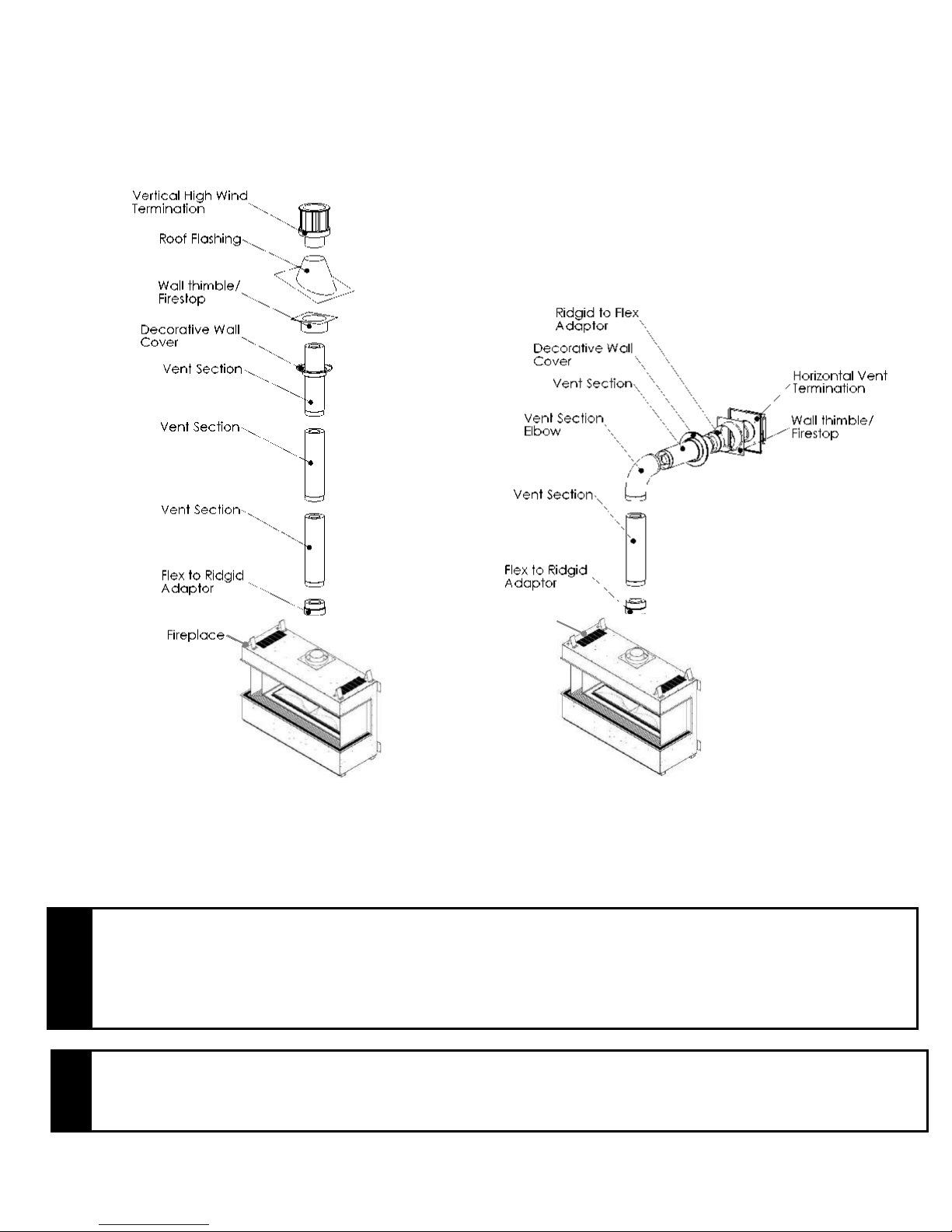
3.3.4 DIRECT VENT INFORMATION / DIRECT VENT D'INFORMATION
NOTE
If at any time the vent-air intake piping is dismantled, use the vent manufacturer’s
instructions and the sealing instructions for reassembly.
Si à tout moment de la tuyauterie d'admission d'air de ventilation est démontée, utilisez la
ventilation instructions du fabricant et les instructions d'étanchéité pour le remontage
NOTE
CONSULT DURAVENT PARTS LIST FOR PART NUMBERS. FOR SECURITY CHIMNEY, ICC AND
METAL FAB CONTACT YOUR LOCAL SUPPLIER.
CONSULTEZ LA LISTE DES PIÈCES DURAVENT POUR LES NUMÉROS DE PIÈCES. POUR LA
CHEMINÉE DE SÉCURITÉ, ICC ET METAL FAB, CONTACTEZ VOTRE FOURNISSEUR LOCAL.
The unit must be connected to listed 2-ply aluminium venting and vent cap / termination kit, 5” flex vent
on the exhaust side and listed 8” flex vent on the air intake side or can be used with Security Venting,
Dura-Vent 5”x 8” with the use of Dura-Vent adapters part #’s 58DVA-FCM & W175-0170, Selkirk Direct-
Temp Venting with adapter, ICC venting with adapter or Metal-Fab direct venting with the use of Metal-
Fab adapter. Install the vent components according to the manufacturer's instructions being sure to use
spacers (see Figure 5) every 3’ to ensure correct spacing is maintained between air intake and exhaust.
Slope horizontal pipe at least 1/4" (6 mm) rise per foot of horizontal run away from the fireplace. Allow 1"
(25 mm) clearance to the vent. Refer to the graph for allowable vent configurations. Be sure to ensure
that termination area allows enough room for adequate combustion and ventilation air and that the flow
of combustion and ventilation air is not obstructed.
L'unité doit être raccordée à une ventilation en aluminium 2 plis et à un kit de terminaison / évent, un
conduit flexible de 5 "du côté échappement et un conduit flexible de 8" du côté entrée d'air ou peut être
utilisé avec Ventilation de sécurité, Dura-Vent 5 "X 8" avec l'utilisation des adaptateurs Dura-Vent
58DVA-FCM et W175-0170, Selkirk Direct-Temp Ventilation avec adaptateur, ventilation CCI avec
adaptateur ou ventilation directe Metal-Fab avec adaptateur Metal-Fab. Installez les composants de
l'évent conformément aux instructions du fabricant en vous assurant d'utiliser des entretoises (voir la
figure 5) toutes les 3 pi pour assurer un espacement correct entre l'entrée et la sortie d'air. Incliner le
tuyau horizontal à une hauteur d'au moins 6 mm (1/4 po) par pied horizontal du foyer, en laissant un
dégagement de 25 mm (1 po) à l'évent. Reportez-vous au graphique pour les configurations d'évent
admissibles. Assurez-vous que la zone de terminaison laisse suffisamment d'espace pour une
combustion et une ventilation adéquates et que le flux d'air de combustion et de ventilation ne soit pas
obstrué.
Figure 5
This appliance’s venting system is room sealed or Direct Vent. This means that it does not require room
air for combustion but draws air from outside the building.
Page 23 of 55

USE OF COUPLERS – WITH FLEX PIPE
In the event of a puncture of the vent pipe or if an extension is needed couplers may be used. High
temperature sealant shall be applied to the ends of the coupler and the coupler shall then be inserted
into the flex vent.
Use 3 #8 x ½” hex head sheet metal screws on
each end of the joint to fasten the coupler to the venting.
FIGURE 6
Dura-Vent or Selkirk Direct-Temp Venting
The minimum vent system for horizontal termination must consist of:
Dura-Vent adapter Part # W175-0170 directly on top of unit or Selkirk adapter
24” (609.6mm) vertical length of vent
90 degree elbow
12" (305 mm) length horizontally
Wall thimble
Dura-Vent Horizontal termination cap 58DVA-HSC or / Selkirk Horizontal termination cap
The maximum horizontal vent system consists of:
Dura-Vent adapter Part # W175-0170 directly on top of unit or Selkirk adapter
40' (12192 mm) vertical length directly on top of the stove
4 - 90 degree elbows
20' (6096 mm) maximum horizontal length
Wall thimble
Dura-Vent Horizontal termination cap 58DVA-HSC or / Selkirk Horizontal termination cap
The maximum vertical system consists of:
Dura-Vent adapter Part # W175-0170 directly on top of unit or Selkirk adapter
Up to 40' (12192 mm) of vertical length
Fire stop
Flashing
Collar
Dura-Vent Termination cap part 58DVA-HSC or / Selkirk Termination cap
ICC VENTING
The minimum vent system for horizontal termination must consist of:
ICC adapter directly on top of unit
24” (609.6mm) vertical length of vent
90 degree elbow
12" (305 mm) length horizontally
Wall thimble
Horizontal termination cap
The maximum horizontal vent system consists of:
ICC adapter directly on top of unit
40' (12192 mm) vertical length directly on top of the stove
4 - 90 degree elbows
20' (6096 mm) maximum horizontal length
Wall thimble
Horizontal termination cap
The maximum vertical system consists of:
ICC adapter directly on top of unit
Up to 40' (12192 mm) of vertical length
Fire stop
Flashing
Collar
Termination cap
Page 24 of 55

Security Venting
The minimum vent system for horizontal termination must consist of:
Dura-Vent adapter Part # W175-0170 directly on top of unit
24” (609.6mm) vertical length of vent
90 degree elbow
12" (305 mm) horizontal length of vent
Wall thimble
Security Venting Horizontal termination cap
The maximum horizontal vent system consists of:
Dura-Vent adapter Part # W175-0170 directly on top of unit
40' (12192 mm) vertical length directly on top of the stove
4 - 90 degree elbows
20' (6096 mm) maximum horizontal length
Wall thimble
Security Venting Horizontal termination cap
The maximum vertical system consists of:
Dura-Vent adapter Part # W175-0170 directly on top of unit
Up to 40' (12192 mm) of vertical length
Fire stop
Flashing
Collar
Security Venting Termination cap
Use a ceiling fire stop when penetrating a ceiling or floor. Use a wall thimble when penetrating
an inside or outside wall. Vent terminals shall not be recessed into a wall or siding.
Metal-Fab Venting
The minimum vent system for horizontal termination must consist of:
Metal-Fab adapter directly on top of unit
24” (609.6mm) vertical length of vent
90 degree elbow
12" (305 mm) length horizontally
Wall thimble
Metal-Fab Horizontal termination cap
The maximum horizontal vent system consists of:
Metal-Fab adapter directly on top of unit
40' (12192 mm) vertical length directly on top of the stove
4 - 90 degree elbows
20' (6096 mm) maximum horizontal length
Wall thimble
Metal-Fab Horizontal termination cap
The maximum vertical system consists of:
Metal-Fab adapter directly on top of unit
Up to 40' (12192 mm) of vertical length
Fire stop
Flashing
Collar
Metal-Fab Termination cap
Page 25 of 55

2-Ply Aluminum Flex Vent
The minimum vent system for horizontal termination must consist of:
24” (609.6 mm) vertical length (measured to center of vent pipe) with a 90 degree bend and a 12”
(305 mm) horizontal length (measured from center of vent pipe)
Wall thimble
Horizontal termination cap TTK58
The maximum horizontal vent system consists of:
40’ (12192 mm) vertical length with a 4 - 90 degree bends and a 20’ (6096 mm) horizontal length
(measured to center of vent pipe)
Wall thimble
Horizontal termination cap TTK58
Note: 2-Ply Horizontal venting shall be supported, by means of a steel strap, every 3’.
The maximum vertical system consists of:
Up to 40' (12192mm) of vertical length
Fire stop
Flashing
Collar
Adapter from flex to Simpson Dura-Vent part 58DVA-FCM
Termination cap
A maximum of 4 – 90 degree bends can be used on the vertical installation venting. The maximum
height for this vent configuration is 40’ (12192 mm) and the minimum height is 4’ (1219 mm).
The maximum horizontal run is a total of 20’ (6096mm). When fastening the flex vent to the termination
and to the unit use a minimum of 3 # 8 x ½” hex head sheet metal screws on the 5” vent and a minimum
of 4 - # 8 x ½” hex head sheet metal screws on the 8” vent.
Page 26 of 55

VERTICAL VENT TABLE
EXAMPLES
MINIMUM VERTICAL (V1 + V2 + V3)
MAXIMUM HORIZONTAL (H1 + H2)
4’
10’ 8’
20’
MAXIMUM VERTICAL HEIGHT = 40’
MAXIMUM HORIZONTAL OFFSETS = 20’
MAXIMUM 90° ELBOWS PERMITTED = 4
EXAMPLES
MINIMUM VERTICAL (V1)
MAXIMUM HORIZONTAL (H1 + H2 + H3 + H4)
4’
10’
8’
20’
NOTE: All vent dimensions are measured from the
appliance surface where the vent connects to the point
where exhaust gases exit the termination.
REMARQUE: Toutes les dimensions sont mesurées à
partir d'aération de la surface de l'appareil où l'évent se
connecte au point où les gaz d'échappement de sortie de
la résiliation.
V1
H1
H2
H3
H4
V1
V2
V3
H1
H2
(All values are in feet)
HORIZONTAL VENT TABLE
(All values are in feet)
Page 27 of 55

34’
20’
A A B B
(Example: Where A---A = Vertical @ 3.5’
12” MINIMUM
40’
And B---B = Horizontal @ 8.75’)
Page 28 of 55
USE OF SEALANT
NOTE
A minimum clearance to combustibles must be maintained around the vent pipe of 1” on
all horizontal and vertical pipe runs
Un dégagement minimum aux matériaux combustibles doit être maintenu autour du tuyau
de 1 "sur toutes les canalisations horizontales et verticales fonctionne
Vent Configuration
Restrictor Size
SEE PAGE 28
60%
SEE PAGE 28
40%
SEE PAGE 28
20%
Apply RTV high temperature
sealant around male pipe.
Restrictor plate
Sealant is required on vent system joints (figure 7), except Metal-Fab Sure-Seal direct vent system joints.
On longer vent runs, especially vertical runs, sealant will ensure that the combustion air enters from
outdoors, and not through the vent joints. Use high temperature sealant, available from local suppliers,
on the inner pipe joint, applying the sealant around the outside of the male part of the vent. A bead of
silicone should be used on the outside of the joint after assembly to seal the supply air. If the venting is
disconnected for servicing, be sure to follow above instructions for resealing venting when reconnecting
to system.
FIGURE 7
VENT RESTRICTOR INSTALLATION
VENT RESTRICTOR
To fasten the Restrictor Plate to the ceiling of the firebox:
1/. Remove the 2 screws that are in place
2/. Align holes in the Restrictor that match the required degree of restriction
3/. Fasten Restrictor Plate back in place.
Page 29 of 55
Typical Dura- Vent, Security Chimney & Metal-Fab Venting Installation:
NOTE
ALLOWING THE VENT PIPE TO SLOPE DOWN TOWARDS THE VENT TERMINATION COULD
CAUSE POOR COMBUSTION AND/OR HIGH TEMPERATURES THAT MAY PRESENT A FIRE
HAZARD.
PERMETTRE LA tuyau de ventilation vers descendent vers la sortie de ventilation POURRAIT
PROVOQUER une mauvaise combustion et / ou de températures élevées qui peuvent présenter des
risques d'incendie.
NOTE
CONSULT DURAVENT PARTS LIST FOR PART NUMBERS. FOR SECURITY CHIMNEY, ICC AND
METAL FAB CONTACT YOUR LOCAL SUPPLIER.
CONSULTEZ LA LISTE DES PIÈCES DURAVENT POUR LES NUMÉROS DE PIÈCES. POUR LA
CHEMINÉE DE SÉCURITÉ, ICC ET METAL FAB, CONTACTEZ VOTRE FOURNISSEUR LOCAL.
Fireplace
Vent terminals shall not be recessed into a wall or siding.
Horizontal Wall Vent Terminations
The position of the horizontal vent termination must be positioned in such a way as to meet all local building
codes. Attach the correct length of pipe. Mark the center line of the pipe facing the wall (allowing for a 1/4” rise
per foot of horizontal, example 10 ft of horizontal would require a rise of 2.5”).
Page 30 of 55

13.50”
10.50”
10.50”
Ø 8.00”
Ø 10.00”
13.50”
10.5 x 10.5 MIN OPENING
WALL THIMBLE 10"
OUTER PIPE 8”
13.50”
10.50”
10.50”
Ø 8.00”
Ø 10.00”
13.50”
10.5 x 10.5 MIN OPENING
WALL THIMBLE 10"
OUTER PIPE 8”
VIEW OF SAFETY CAGE
Mark a 10.5” x 10.5” square around the center mark (inside dimensions). Cut and frame the exterior wall to accept
the wall thimble. Install the wall thimble, on the inside of the exterior wall shield using wood screws.
Attach the venting to the termination using sheet metal screws, for 2 Ply Aluminum Flex installations Inca Metal
Cutting’s termination part shall be used and when using Simpson Dura-Vent, Security Venting, ICC or Metal-Fab
consult your local supplier for part numbers.
To install the termination attach the 5” exhaust to the termination and fasten with 3 #8 x ½” hex head sheet metal
screws then attach the 8” vent to the termination and fasten with 4 #8 x ½” hex head sheet metal screws, be sure
that the flex vent overlaps the termination collars a minimum of 2”. Then attach the termination to the exterior wall
using four wood screws through the holes in the corner of the vent terminal.
The next step is to apply a bead of mil-pac or RTV 106 to top of the 5” exhaust collar on the unit and attach the 8”
vent using screws (as described above), finally apply a bead of mil-pac or RTV 106 to top of the 8” vent and attach
(as described above).
Safety Cage / Cage de sécurité
A safety cage may be required on low terminations. Please check with your local safety authority.
Une cage de sécurité peut être nécessaire de faibles terminaisons. S'il vous plaît vérifiez auprès de votre
autorité de sécurité locale.
Page 31 of 55

NOTE
DO NOT PACK AIR SPACES WITH INSULATION
NE PAS PACK ESPACES D'AIR AVEC ISOLATION
NOTE
ALWAYS CHECK YOUR LOCAL CODES BEFORE INSTALLING VENTING. CLEARANCES ETC, MAY
VARY FROM STATE TO STATE (PROVINCE TO PROVINCE).
TOUJOURS vérifier les codes locaux avant l'installation VENTILATION. ETC DÉGAGEMENTS, peut
varier d'ÉTAT (PROVINCE).
NOTE
CONSULT DURAVENT PARTS LIST OR INCA METAL CUTTING PARTS LIST FOR PART NUMBERS.
FOR SECURITY CHIMNEY, ICC AND METAL FAB CONTACT YOUR LOCAL SUPPLIER.
CONSULTEZ LA LISTE DES PIÈCES DURAVENT OU LA LISTE DES PIÈCES DE DÉCOUPE
MÉTALLIQUES INCA POUR LES NUMÉROS DE PIÈCES. POUR LA CHEMINÉE DE SÉCURITÉ, ICC ET
METAL FAB, CONTACTEZ VOTRE FOURNISSEUR LOCAL.
11” x 11”
opening
Vertical Installations
Always maintain a 1” clearance around the vent pipe (vertical) and 1” clearance horizontal, when passing through
ceilings, walls, roofs, enclosures, attic rafter or any combustible surfaces.
When passing through a flat ceiling install a Box/Wall thimble. Cut an 11” square hole and frame as shown in
the diagram below.
See section 3.3.4 Venting for instructions on how to connect Security or Dura-vent venting.
Page 32 of 55

Termination above Roof
3”
12” from
grade
Consult local codes for minimum vent cap height above the roof (X), vent must be a minimum of 2’ from any wall.
To prevent water seepage; install the flashing with upper portion under the roofing material and the lower portion
over the roofing material.
Note: Do not fasten down until the final adjustments to the vent have been made.
The diagram at right shows the
minimum clearances as per the
chart on page 34.
Page 33 of 55

0” 0”
3” 3”
1 In accordance with the current CSA B149.1,
Natural Gas and Propane Installation Code
2 In accordance with the current ANSI Z223.1 /
NFPA 54, National Fuel Gas Code
† A vent shall not terminate directly above a
sidewalk or paved driveway that is located
between two single family dwellings and
serves both dwellings
‡ Permitted only if veranda, porch, deck or
balcony is fully open on a minimum of two
sides beneath the floor
* For clearances not specified in ANSI Z223.1 /
NFPA 54 or CSA B149.1 one of the following
shall be indicated
a). A minimum clearance value determined by
testing in accordance with section 2.23.5, or:
b). A reference to the following footnote:
“Clearance in accordance with local installation
codes and the requirements of the gas supplier.”
24” 24”
J= Clearance to nonmechanical 6 in (15cm) for appliances ≤10,000 6 in (15cm) for appliances ≤10,000
air supply inlet to building or Btuh (3kW), 12 in (30 cm) for Btuh (3kW), 9 in (23 cm) for
the combustion air inlet to appliances >10,000 Btuh (3kW) and appliances >10,000 Btuh (3kW0 and
any other appliance ≤100,000 Btuh (30kW), 36 in (91 cm) ≤50,000 Btuh (15kW), 12 in (30cm)
for appliances >100,000 Btuh (30kW) for appliances >50,000 Btuh (15kW0
K= Clearance to a mechanical 6 ft (1.83 m) 3 ft (91 cm) above if within 10ft
air supply inlet (3 m) horizontally
L= Clearance above paved sidewalk 7 ft (2.13 m) †
or paved driveway located on
public property *
M= Clearance under veranda, 12 in (30 cm) ‡
porch deck or balcony *
Page 34 of 55
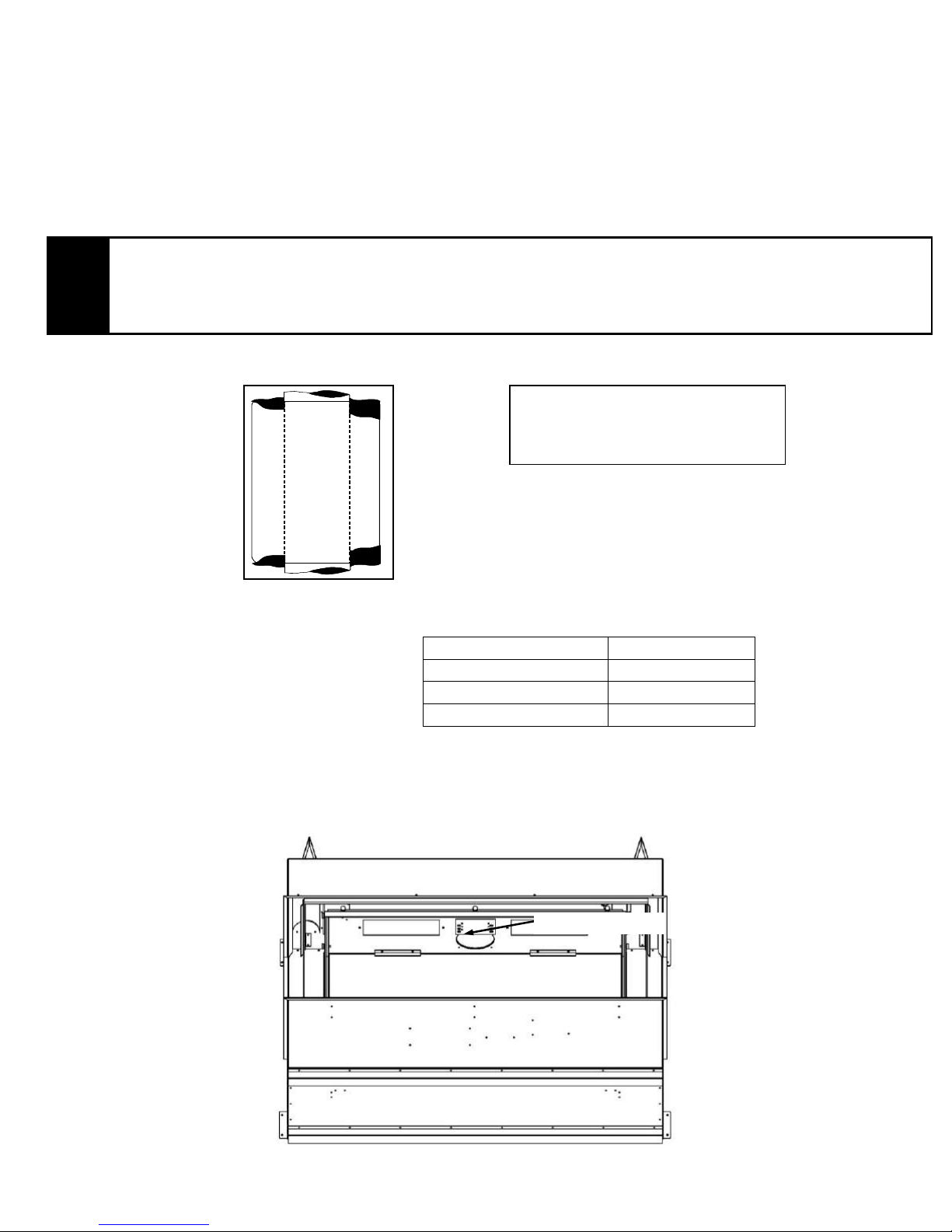
3.3.5 LOGS, ROCKS AND GLASS PEBBLE INSTALLATION
CAU TION
ATTENTION
Burn media positions are critical to the safe and clean operation of this appliance.
Never add any other material into the firebox. Use only with burn media supplied with
this unit.
Les positions des médias de brûlure sont critiques au fonctionnement sûr et propre de
cet appareil. N'ajoutez jamais d'autres matériaux dans la chambre de combustion.
Utilisez uniquement avec les supports de gravure fournis avec cet appareil.
This shows positions of media critical
to correct flame pattern.
It is critical that logs 3
& 4 cross the burner
where the single row of
burner holes are.
Step 1.
Note the burner pattern before you commence installing the burn media.
Step 2
Install the 1st log to the left back side of the firebox behind the burner holes
Page 35 of 55

Step 3
Install the 2nd log to the right back side of the fireplace behind the burner holes
Step 4
Your installed 2 logs should lay positioned as below
Step 5
Install the 3rd log over the portion of the burner pan with only one row of holes on the right side of the
fireplace.
Step 6
Install the 4th log over the portion of the burner pan with only one row of holes on the left side of the
fireplace.
Page 36 of 55

Step 6
Your installed 4 logs should lay positioned as below.
Step 7
Install the ceramic rocks in an esthetically pleasing pattern, as few or as many as you want. The rocks
may not be placed over any of the burner holes or the vent holes at the front of the burner so they do not
affect the burn pattern in any way.
Step 8
Carefully scatter the glass pebbles over the burner pan. These can go over the burner holes. Make sure
none of the pebbles drop into the pilot assembly hole or down into any of the fans. Do not cover the vent
holes in the front of the burner pan.
Page 37 of 55

3.3.6 INNER & OUTER GLASS PANEL REMOVAL & INSTALLATION.
Thumb screws
BE VERY CAREFUL WHEN HANDLING THE GLASS. DO NOT DAMAGE
OUTER GLASS PANEL REMOVAL
1/. Do not attempt removal until fireplace and glass are cool to touch. Remove front air intake louver
2/. Unscrew the 3 front thumbscrews at the bottom so they are loose and slide back towards yourself
3/. Install glass suction cup lifter, do not attempt removal without suction lifter firmly attached.
4/. With aid of suction lifter, lift glass straight up, then while lowering the glass, carefully angle bottom towards you
and past front of fireplace until cleared at the bottom. Be extra careful so as not to damage glass.
5/. Removal of the front and side panels of glass is the same, but side panels do not have to be removed unless
damaged
INNER GLASS PANEL REMOVAL.
1/. Do not attempt removal until fireplace and glass are cool to touch. Remove inner louvers and use an exacto knife to
cut silicone at front 2 corners before attempting to remove the glass.
2/. Install glass suction cup lifter, do not attempt removal without suction lifter firmly attached.
3/. Remove the top 3 thumbscrews
4/. Hold suction cup lifter and loosen the bottom 3 screws, unlike the top thumbscrews these do not
need to be completely removed but leave the bottom channel in place.
5/. With aid of suction lifter, lift glass straight up, then while lowering the glass, carefully angle bottom towards you
and past front of fireplace until cleared at the bottom. Be extra careful so as not to damage glass.
6/. The inner side glass should not need to be removed unless damaged as it is easily accessible once the front glass is
off
INNER GLASS PANEL INSTALLATION.
Carefully angle the front glass up into the top of the fireplace then lower into bottom glass channel. Lightly tighten the 3
thumb screws at the bottom. Install 3 thumb screws lightly to hold the top of the glass. Make sure the glass is even with
the side glass then hand tighten all 6 thumb screws. After installing the glass both corners must be sealed with a thin
bead of clear high temperature silicone (supplied).
OUTER GLASS PANEL INSTALLATION.
Replace the inner louvers before installing the outer glass.
Installation of the outer sides and front glass is the same. The outer glass panel with the glass support strip on, fits up
into 2 clips at the top of the fireplace as shown in the diagram below. Once top is in the clips push the bottom of the
glass in and slide down until it locks into the brackets at the top, tighten the thumb screws lightly. Make sure the glass is
aligned with the side glass and is installed properly before tightening the thumb screws.
Page 38 of 55

NOTE
It is normal for the appliance to expand and contract while it heats up or cools down whether this is from a cold start or a
steady-state condition where the fan has come on or off. Under these circumstances it is possible that the
expansion/contraction of the metal parts may produce sounds.
Il est normal que l 'appareil à dilater et se contracter pendant qu'elle se réchauffe ou se refroidit s'il s'agit d'un démarrage à
froid ou d'un état d'équilibre où le ventilateur est venu sous ou hors tension. Dans ces circonstances, il est possible que
l'expansion et la contraction des pièces métalliques peuvent produire des sons
WARNING
AVERTISSEMENT
Do not operate this appliance with the glass removed, cracked or broken.
Replacement of the glass should be done by a licensed or qualified service person.
For use with glass certified with the appliance only
Do not use any substitute materials
Do not abuse glass by striking
Ne faites pas fonctionner cet appareil avec le verre retiré, fissuré ou cassé.
Le remplacement du verre doit être effectué par un technicien agréé ou qualifié.
• Pour utilisation avec du verre certifié avec l'appareil uniquement
• N'utilisez aucun matériau de substitution
• Ne pas abuser du verre en frappant
3.3.7 INITIAL FIRING
When lit for the first few times, the appliance may emit an odor resulting from evaporation of paint and lubricants
used in the manufacturing process. Open a door or window (or both) for ventilation. Anyone with a respiratory
condition may need to leave the room during the initial firings. Burn for a minimum of 4 hours on high with the fans
on low to clear this condition. Do not touch the glass during burn in.
Occasionally, after a cold start, vapor may condense and fog the glass, and the flames may be partially blue. After
a few minutes the moisture will disappear and the flames will become yellow. Visually check the flame after warmup. / Parfois, après un démarrage à froid, la vapeur peut se condenser et voiler le verre, et les flammes peuvent
être partiellement bleu. Après quelques minutes, l'humidité disparaît et les flammes deviendront jaunes. Contrôler
visuellement la flamme après l'échauffement.
3.3.8 PILOT FLAME ADJUSTMENT
For proper operation, the pilot and main burner flames must be steady and not lifting off or floating. The top 3/8” –
1/2” (10-13mm) of the
Thermocouple should be
engulfed by the pilot flame.
3.3.9 PRIMARY AIR ADJUSTMENT / AJUSTEMENT DE L'AIR PRIMAIRE
Aeration is factory set but may need adjustment for altitude or movement during shipping. / L'aération est réglée
en usine, mais peut nécessiter un ajustement de l'altitude ou le mouvement pendant le transport.
To adjust the air shutter / Pour ajuster l'obturateur d'air
1/. Turn off the gas / Fermez le gaz
2/. Remove the front outer and inner glass / Retirez les vitres extérieure et intérieure avant
3/. Remove glass or logs from burner / Retirer le verre ou des billes de brûleur
4/. Remove the burner pan / Retirer la casserole du brûleur
5/. Undo the set screw on the air shutter and adjust accordingly then retighten the set screw. / Défaire la
vis de réglage sur le volet d'air et d'ajuster en conséquence, puis resserrez la vis de réglage.
Page 39 of 55

Altitude
Natural Gas –
Orifice Size
Propane Gas –
Orifice Size
0 – 4500 ft (0 – 1372 m)
48
56
4500 – 6500 ft (1372 - 1981 m)
49
57
6500 – 8500 ft (1981 - 2591 m)
50
58
CAUTION
ATTENTION
PARTS REQUIRING ADJUSTMENT DURING OPERATION MAY BE HOT.
PIECES NECESSITANT REGLAGE PENDANT LA MARCHE PEUT ETRE CHAUDE
Air tube and Air shutter shown removed
for clarity purposes only.
Set Screw
6/. Reassemble the fireplace in reverse order from 4 through 2. / Remonter la cheminée dans l'ordre
inverse de 4 à 2.
7/. Turn on the gas. / Allumez le gaz.
Factory Setting
Natural Gas – open 1/4” (6.35mm)
Propane Gas – Fully Open
Aeration adjustment is important for the correct functioning of the appliance. Carbon build up, flame
lifting or any malfunction due to improper aeration adjustment during installation is not covered under the
factory warranty.
Réglage de l'aération est importante pour le fonctionnement correct de l'appareil. Une accumulation de
carbone, de levage flammes ou de toute défaillance due à une mauvaise aération d'ajustement lors de
l'installation n'est pas couvert par la garantie d'usine.
3.3.10 ALTITUDE ADJUSTMENT
All valves have been pre-set and certified for installation at elevations from 0 – 4500 feet (0-1372m)
above sea level. The appliance is certified to CSA 2.17- M91 – gas fired appliances for use at high
altitudes.
When installing this unit at higher elevations, it is necessary to decrease the input rating by replacing the
existing burner orifice with a smaller size for installations over 4500 feet (1372m). For the USA, de-rate
the unit from sea level according to the gas installation code.
Toutes les vannes ont été pré-set et certifié pour l'installation à une altitude de 0 à 4500 pieds (0-1372m)
au dessus du niveau de la mer. L'appareil est certifié à la norme CSA 2.17- M91 - appareils à gaz pour
une utilisation à haute altitude. Lors de l'installation de cet appareil à haute altitude, il est nécessaire de
baisser la note d'entrée par le remplacement de l'orifice du brûleur existant avec une taille plus petite
pour les installations de plus de 4500 pieds (1372m). Pour les États-Unis, de taux de l'unité de niveau de
la mer selon le code d'installation de gaz
Page 40 of 55

3.3.11 FAN ACCESSIBILITY / FAN ACCESSIBILITÉ
CAUTION
ATTENTION
TURN THE MAIN GAS & POWER OFF TO FIREPLACE BEFORE COMMENCING ANY WORK ON THE
FIREPLACE THIS SHOULD BE DONE BY A LICENSED, CERTIFIED GAS INSTALLER
TURN LE PRINCIPAL GAZ ET MISE HORS TENSION AU FOYER AVANT DE COMMENCER TOUT
TRAVAIL SUR LA FOYER CELA DEVRAIT ETRE FAIT PAR UNE LICENCE, VOTRE FOURNISSEUR DE
GAZ
CAUTION
ATTENTION
THE 3 FANS IN THIS FIREPLACE (TWO IN THE FRONT AND ONE IN THE MIDDLE AT THE BACK) ARE
CONNECTED TO A HI/LOW THERMODISC, THE UNIT CAN NOT BE OPERATED WITHOUT THE FANS
GOING AS THE GLASS TEMPERATURE WILL EXCEED THE ALLOWABLE STANDARD OF 172F
DEGREES.
SEE DIAGRAM BELOW.
LES 3 VENTILATEURS DE CE FOYER (DEUX À L'AVANT ET UN AU MILIEU À L'ARRIÈRE) SONT
RACCORDÉS À UN THERMODISQUE HAUT / BAS, L'UNITÉ NE PEUT PAS FONCTIONNER SANS QUE
LES VENTILATEURS PUISSENT DÉPASSER LA NORME ADMISSIBLE DE 172F DEGRÉS.
VOIR SCHÉMA CI-DESSOUS.
1/. Remove the air intake louver at the front of the fireplace
2/. Remove the outer glass as per instructions on page 38
3/. Remove the inner louvers
4/. Remove the fan ducts as shown in diagram above right
5/. Lift the fan out, fans are attached to the metal floor of the fireplace with heavy duty magnets as
shown below.
6/. Once removed from the floor the fan will slide out through the opening.
7/. When replacing fans make sure they line up totally with the fan ducts once the fan ducts are put back
into place. This will ensure the air is properly circulated between the 2 glass panels to maintain the
outer glass temperature as certified.
8/. To replace fan and reassemble the fireplace go in reverse order from steps 7 through 1.
Page 41 of 55
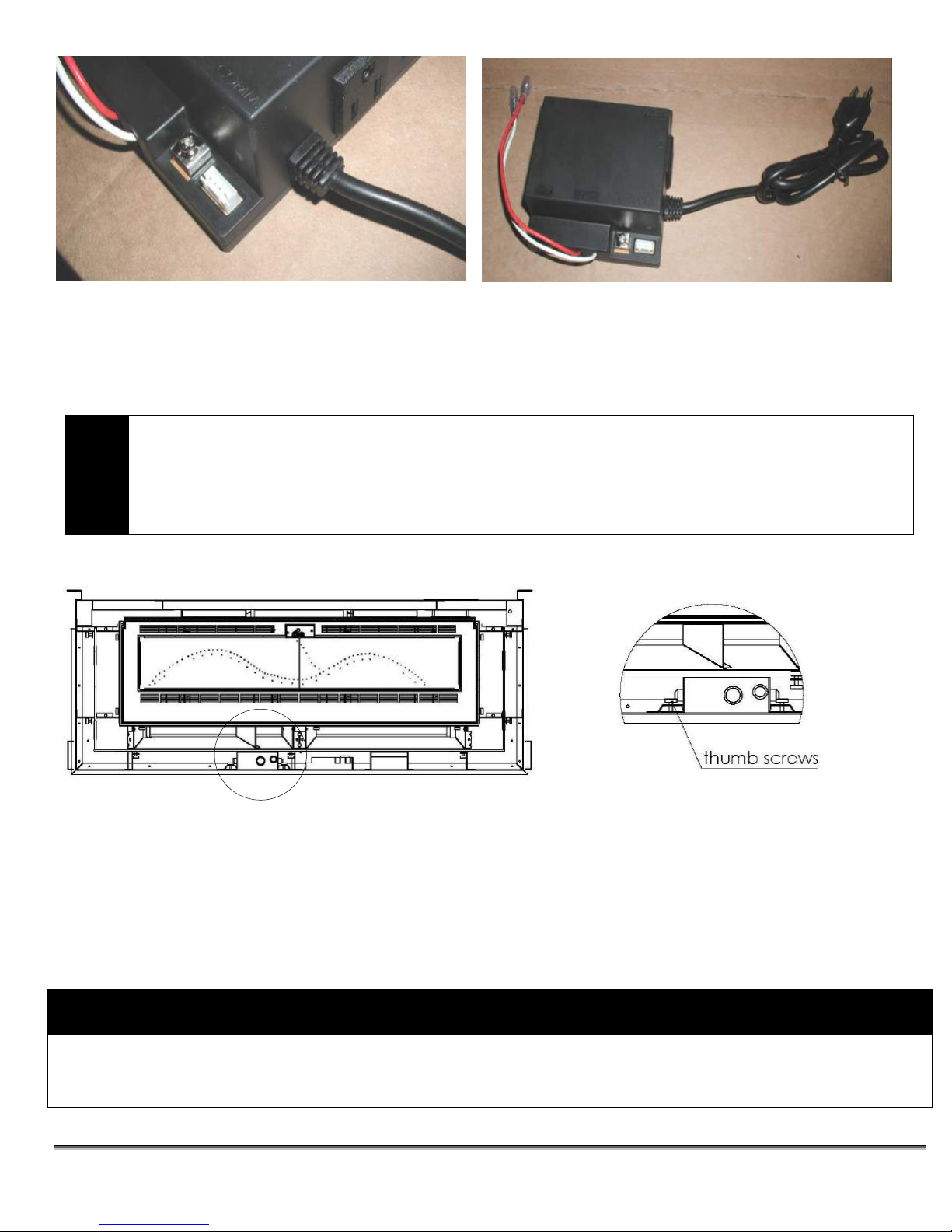
The pictures above show the electrical box that controls the fan, the power cord attached and the strain relief
CAUTION
ATTENTION
TURN THE MAIN GAS & POWER OFF TO FIREPLACE BEFORE COMMENCING ANY WORK ON
THE FIREPLACE THIS SHOULD BE DONE BY A LICENSED, CERTIFIED GAS INSTALLER
TURN LE PRINCIPAL GAZ ET MISE HORS TENSION AU FOYER AVANT DE COMMENCER
TOUT TRAVAIL SUR LA FOYER CELA DEVRAIT ETRE FAIT PAR UNE LICENCE, VOTRE
FOURNISSEUR DE GAZ
WARNING
AVERTISSEMENT
BE CERTAIN TO CHECK FOR GAS LEAKS AT ALL GAS CONNECTIONS AFTER REINSTALLATION OF VALVE.
IL EST INDISPENSABLE DE VÉRIFIER LES FUITES DE GAZ A TOUS LES CONNEXIONS DE GAZ APRÈS LA
RÉINSTALLATION DE LA VANNE.
connected to the box. / Les photos ci-dessus montrent la boîte électrique qui contrôle le ventilateur, le cordon
d'alimentation fourni et le réducteur de tension connecté à la boîte.
3.3.12 GAS VALVE ACCESSIBILITY / ACCESSIBILITÉ ROBINET DE GAZ.
1/. Remove the outer louver and the outer front glass.
2/. Remove the 2 thumbscrews that hold the valve in place and the valve will lift up to remove the
connected gas pipe and pilot.
3/. The IPI (control box) will just lift out. Be careful when lifting out as you may have to remove some
wires off the box.
4/. The fan module will also lift up and out. Be careful when removing this module as the wires are
attached to the underside of the module.
Page 42 of 55

4.0 MAINTENANCE
WARNING
AVERTISSEMENT
TURN OFF THE GAS TO THE MAIN BURNER AND ALLOW THE FIREPLACE TO COOL FOR UP TO
30 MINUTES BEFORE SERVICING.
COUPER LE GAZ AU BRÛLEUR PRINCIPAL ET PERMETTRE AU FOYER DE REFROIDIR JUSQU'À
30 MINUTES AVANT L'ENTRETIEN.
4.1 MAINTENANCE SAFETY / SÉCURITÉ ENTRETIEN
Service and repair should be done by a qualified service person. The appliance should be inspected
before use and at least annually by a professional service technician. More frequent cleaning may be
required due to excessive lint from carpeting, bedding material, etc. It is important that the outer louvers,
burner, and circulating air passageways be kept clean to provide for adequate combustion and
ventilation airflow. Do not substitute materials or use components other than factory supplied. The
appliance area must be kept clear and free from combustible materials, gasoline and other flammable
liquids and vapors.
Entretien et réparation doit être effectuée par un technicien qualifié. L'appareil doit être inspecté avant
son utilisation et au moins une fois par an par un technicien de service professionnel. Un nettoyage plus
fréquent peut être nécessaire en raison des peluches provenant des tapis litière, etc. Il est important que
les persiennes extérieures, le brûleur et les passages de circulation d'air soient maintenus propres pour
assurer une combustion adéquate et un flux d'air de ventilation. Ne pas remplacer les matériaux ou
utiliser des composants autres que l'usine fournie. La zone appareil doit rester clair et exempt de
matériaux combustibles, essence et autres vapeurs et liquides inflammables.
4.2 RECOMMENDED SERVICE / SERVICE RECOMMANDÉ
1. The venting system should be annually inspected by a qualified agency. / Le système de ventilation
devrait être inspectés annuellement par une agence qualifiée.
2. Visually check the burner and pilot flames occasionally. Visually inspect height and color of
flames / Contrôler visuellement le brûleur et les flammes pilotes à l'occasion. Inspecter
visuellement la hauteur et la couleur de flammes
3. Clean the glass as needed. See section 4.3 for instructions on glass cleaning. / Nettoyez la vitre au
besoin. Voir la section 4.3 pour obtenir des instructions sur le nettoyage du verre.
4. Have the appliance inspected annually by a professional service technician. / Avez l'appareil inspecté
annuellement par un technicien de service professionnel.
5. Clean the appliance regularly. / Nettoyez l'appareil régulièrement.
Annual service: An annual service call should take between 1 – 2 hours. Start by disassembling the
unit; take off the outer and inner glass and remove all the embers, burner, and logs. Clean fan with a
vacuum to remove any dust. Vacuum the whole firebox and all the air passages. Clean the burner. After
everything is clean, check all the connections and the chassis ground and reassemble. Clean the glass.
L'entretien annuel: Un appel de service annuelle devrait prendre entre 1 - 2 heures. Commencez par
démonter l'unité; enlever les vitres extérieure et intérieure et enlever toutes les braises, le brûleur et les
bûches. Nettoyer ventilateur avec un aspirateur pour enlever toute trace de poussière. Passez
l'aspirateur sur le foyer entier et tous les passages d'air. Nettoyer le brûleur. Après tout est propre,
vérifier toutes les connexions et la masse du châssis et montons. Nettoyez la vitre.
Page 43 of 55

4.3 GLASS CLEANING / NETTOYAGE DE LA VITRE
WARNING
AVERTISSEMENT
THE FOLLOWING PROCEDURE IS TO BE PERFORMED BY QUALIFIED PERSONNEL ONLY
TURN OFF THE GAS TO THE MAIN BURNER AND ALLOW THE HEATER TO COOL FOR UP TO 30
MINUTES BEFORE SERVICING.
LA PROCÉDURE SUIVANTE EST EFFECTUER PAR DU PERSONNEL QUALIFIÉ
COUPEZ LE GAZ AU BRÛLEUR PRINCIPAL ET LAISSEZ L'APPAREIL REFROIDIR PENDANT
JUSQU'À 30 MINUTES AVANT L'ENTRETIEN.
The inside of the glass may require periodic cleaning to remove deposits left from impurities in the gas
and combustion air. For best results, use a ceramic glass cleaner or polish (e.g. cerama bryte stove
cleaner). Avoid the use of ammonia based cleaners such as Windex®. Do not clean while hot. Do not
use abrasive cleaners. Make sure you clean off any white film on the fireplace glass as soon as possible
– otherwise the glass may deteriorate.
L'intérieur du verre peut nécessiter un nettoyage périodique pour éliminer les dépôts laissés par les
impuretés présentes dans le gaz et l'air de combustion. Pour de meilleurs résultats, utilisez un nettoyant
pour vitres en céramique ou un produit de polissage (par exemple un nettoyant pour cuisinière en
céramique bryte). Évitez l'utilisation de nettoyants à base d'ammoniaque comme Windex®. Ne pas
nettoyer à chaud. N'utilisez pas de nettoyants abrasifs. Assurez-vous de nettoyer tout film blanc sur la
vitre du foyer dès que possible - sinon la vitre pourrait se détériorer.
4.4 BURNER & PILOT CLEANING / BRULEUR ET NETTOYAGE DE PILOTE
Periodic cleaning is necessary for proper operation. Remove the burner, and check that the burner orifice
is clean. Visually inspect the pilot. Brush or blow away any dust, lint, or foreign debris. If the pilot orifice
is plugged, disassembly may be required to remove any foreign material from the orifice or tubing. When
the appliance is back in service, check the pilot flame pattern. For re-lighting, refer to the lighting
instructions in Section 2.1.
Un nettoyage périodique est nécessaire pour un fonctionnement correct. Enlever le brûleur, et vérifier
que l'orifice du brûleur est propre. Inspectez visuellement le pilote. Brossez ou soufflez la poussière, les
peluches ou les débris étrangers. Si l'orifice pilote est branché, le démontage peut être nécessaire pour
éliminer toute matière étrangère de l'orifice ou un tube. Lorsque l'appareil est remis en service, vérifier le
modèle flamme de la veilleuse. Pour ré-éclairage, reportez-vous aux instructions d'éclairage dans la
section 2.1.
4.5 VALVE AND PILOT ASSEMBLY REPLACEMENT / SOUPAPE ET
REMPLACEMENT ENSEMBLE PILOTE
1. Turn off the gas at the meter. / Coupez le gaz au compteur.
2. Follow the instructions in 3.3.12 to access the valve
3. Remove the burner by loosening the screws and lifting it out see section 3.3.10. If the decorative
glass is removed from the burner pan make sure you do not get any medium around the pilot when
replacing it. / Enlever le brûleur en desserrant les vis et en soulevant it out voir la section 3.3.10. Si le
verre décoratif est retiré de la cuvette du brûleur assurez-vous que vous ne recevez pas n'importe
quel support autour du pilote lors de son remplacement.
Page 44 of 55

4. Disconnect the gas line to the appliance and disconnect the gas line from the valve to the main
SYMPTOM
POSSIBLE CAUSE
CORRECTIVE ACTION
I. Pilot will not light after
repeated triggering of the
remote control – intermittent
pilot
A. No spark at electrode (weak or not heat source for pilot ignition)
1. Improper ignition
1. Align the electrode with 1/8” (3mm) gap to
pilot hood
2. Poor connections at starter and
ignition electrode
2. Reconnect if loose
1. Broken ceramic cover on
ignition electrode
3. Replace pilot assembly
2. Battery power low or dead
4. Replace batteries
B. No gas or low gas pressure
5. Gas line shut off(s) may not be
turned on
5. Turn on shut-off valves
1. Air in gas lines
1. Purge gas lines
2. Gas lines may not be
connected
2. Connect all gas lines
3. Low pressure may be caused
by bent line
3. Check for a kinked line
II. Pilot will not stay lit after
following the lighting
instructions
A. Thermocouple / Valve
1. Weak or improperly located pilot
flame
1. Adjust and clean pilot. The flame must
impinge on or engulf the thermocouple, as
shown in Figure 27.
2. Defective thermocouple
2. Replace thermocouple
orifice. / Débrancher la conduite de gaz à l'appareil et débranchez la conduite de gaz de la vanne à
l'orifice principal.
5. Remove the thumbscrews holding the valve bracket to the base of the unit and lift valve & valve
bracket out. / Retirez les vis à ailettes maintenant le support de soupape à la base de l'unité et
soulevez la soupape et le support de soupape.
6. Undo the pilot gas line at the gas valve. / Annuler la conduite de gaz pilote à la vanne de gaz.
7. Disconnect the thermostat or on/off switch wires from the valve (if applicable). / Débranchez le
thermostat ou marche / arrêt fils de l'interrupteur de la vanne (si applicable).
8. Remove the gas line to the valve inlet and outlet. / Retirer la conduite de gaz à l'entrée de la vanne et
la sortie.
9. Remove the screws which hold the valve to the valve bracket. / Retirez les vis qui maintiennent la
vanne sur le support de la vanne.
10. Remove the screws fastening the pilot assembly to the pilot bracket and remove the pilot assembly. /
Retirez les vis de fixation du assemblage de la veilleuse sur le support de pilote et retirer l'ensemble
pilote.
11. Reassemble the components in reverse order. / Remonter les composants dans l'ordre inverse.
5.0 TROUBLE SHOOTING
Page 45 of 55

3.Thermocouple not installed
properly
3. Make sure all wire connections at the gas
valve terminals are tight and the
thermocouple is fully inserted into the
mounting bracket
4. Open wire connection in pilot
circuit
4. Check wire continuity and connections in
the pilot circuit
5. Defective Valve
5. Check with your voltmeter.
B. Defective safety circuit
1. Loose or defective connections
1. Check continuity, tighten wiring or
connections, and repair
III. Main burner will not light
A. Valve / Switches
1. Valve control off
1. Turn to “ON” position
2. Blockage at the burner (line,
orifice, or ports)
2. Check and clean
3. Defective remote
1. Conduct a continuity test or jumper wire
test and replace if defective, check
batteries
4. Defective wiring or connections
2. Conduct a test with a jumper wire and
repair as required
5. Defective Valve
3. Contact service technician
I. Soot deposits
1. Air inlet blocked or restricted
1. Clean air inlets
2. Vent system is restricted or
inadequate
2. Confirm venting & termination are those
which are approved with the appliance
3. Logs are sooting up
3. Check manual for correct log placement
V. Flame burns blue and lifts
off burner
1. Insufficient combustion air being
supplied
1. Ensure that no foreign material blocks air
inlets. Ensure the vent is adequate
2. Manifold pressure set too high
2. Check manifold pressure
3. Vent system restricted
3. Check vent system
VI. Main flame does not burn
properly
1. Incorrect vent or termination
used.
1. Confirm venting & termination are those
which are approved with the appliance
VII. Flames impinge on firebox
top
1. Vent system is restricted or
inadequate
1. Correct flue as required
2. Manifold pressure too high
2. Check manifold pressure as required
Page 46 of 55

6.0 REPLACEMENT PARTS
When requesting service or replacement parts for your unit, please provide model name and serial
number. All parts listed below may be ordered from an authorized dealer.
Description Part# Certification
Door Inner Front Glass 3007 ASTM C1048
Door Inner Side Glass 3015 ASTM C1048
Door Outer Front Glass 3006 ASTM C1048
Door Outer Side Glass 3058 ASTM C1048
Door Glass Gasket .5 rope N/A
Inner Black Glass Liner 3104 ASTM C1048
Burner Left & Right 3110 - 3111 N/A
Fan (3 pieces) 3180 CSA / UL
(2 front fans @ 15” long, 1 back fan @ 10.75” long)
Orifice – NG (x2) MP0505-48 N/A
Orifice – LP (x2) MP0505-56 N/A
Intermittent Pilot & Remote Control Valve Parts
Description Part#
Pilot Assembly (Intermittent) NA292 CSA / UL
Valve (with step motor installed) AF-4044 CSA C & US
Remote Step Motor for AF-4000 Valve AF-4000MOT CSA C & US
Supreme Control Module, incl.wire harness VCS-4000MODS01TC CSA C & US
Plug-in Adapter ((7.5V A/C & 24” wires) AF-4000ADP24 CSA C & US
Extension Module for 120V operation AF-4000120MODS01 CSA C & US
Supreme Handheld transmitter AF-4000HHS04 CSA C & US
Page 47 of 55

7.0 INCA METAL CUTTING’S WARRANTY PROTECTION FOR ALL INCA
METAL CUTTING GAS FIREPLACE PRODUCTS
Inca Metal Cutting’s products are designed with superior components and materials, assembled by trained
craftsmen who take great pride in their work. The burner and valve assembly are leak tested and test fired at a
quality control test station. Once assembled the complete fireplace is thoroughly inspected by a qualified
technician, before packaging, to ensure that you, the customer, receives the quality product that you expect from
Inca Metal Cutting’s.
INCA METAL CUTTING’S GAS FIREPLACE’S WARRANTY
Your Inca Metal Cutting gas fireplace is guaranteed to be free of defects in materials and workmanship for a period
of 5 years from the date of purchase. This covers: combustion chambers, heat exchangers and burners as well as
stainless steel parts against tarnishing.
Electrical (110 volt and millivolt) components and wearable parts such as blowers, gas valves, thermal
switches, switches, wiring, remote controls, igniters, gaskets, glass (thermal damage only) and pilot assemblies
are covered for 1 year and Inca Metal Cutting will provide replacement parts free of charge during the first year of
the limited warranty. Glass damaged through negligence on removal or installation is not covered under warranty.
CONDITIONS AND LIMITATIONS
Inca Metal Cutting warrants its products against manufacturing defects to the original purchaser only – i.e. the
individual or legal entity (registered customer) whose name appears on the original invoice – provided that the
purchase was made through an authorized Inca Metal Cutting dealer and is subject to the following conditions and
limitations:
This factory warranty is nontransferable and may not be extended whatsoever by any of our representatives.
A licensed, authorized service technician or contractor must have installed the gas fireplace. Installation must be
done in accordance with the installation instructions included with the product and all local and national building
and fire codes.
This limited warranty does not cover damages caused by misuse, lack of maintenance, accident, alterations,
abuse or neglect. Parts installed from other manufacturers will nullify this warranty.
This limited warranty further does not cover any scratches, dents, corrosion or discoloring caused by excessive
heat, abrasives, chemical cleaners nor any venting components used in the installation of the fireplace.
This warranty does not cover any problems caused to installation used venting or vent terminations which are not
certified for use with this product.
Any installation, labor, construction, transportation or other related costs or expenses arising from defective
part(s), repair or replacement or otherwise of same, will not be covered by this warranty nor shall Inca Metal
Cutting assume responsibility for same. Further, Inca Metal Cutting will not be responsible for any incidental,
indirect or consequent damages, except as provided by law, and in no event shall they exceed the original
purchase price.
In the first year only, this warranty extends to the repair or replacement of warranted parts, which are defective in
material or workmanship provided that the product has been operated in accordance with the operation
instructions and under normal conditions.
After the first year, Inca Metal Cutting may, at its discretion, fully discharge all obligations with respect to this warranty
by refunding to the original warranted purchaser the wholesale price of any warranted but defective parts.
Page 48 of 55

CONDITIONS AND LIMITATIONS (continued)
Notwithstanding any provisions contained in this warranty, Inca Metal Cutting’s responsibility under this warranty is
defined as above and it shall not in any event extend to any incidental, consequential or indirect damages.
This warranty defines the obligations and liability of Inca Metal Cutting with respect to the Inca Metal Cutting gas
fireplace and any other warranties expressed or implied with respect to this product, its components or
accessories are excluded.
Inca Metal Cutting neither assumes, nor authorizes any third party to assume, on its behalf, any other liabilities
with respect to the sale of this product. Inca Metal Cutting will not be responsible for: over firing, downdrafts,
spillage caused by environmental conditions such as rooftops, buildings, nearby trees, hills, mountains,
inadequate vents, excessive venting configurations, insufficient make up air, or negative air pressures which may
or may not be caused by mechanical systems such as exhaust fans, furnaces, clothes dryers, etc.
Any damages to fireplace, combustion chamber, trim or other component due to water, weather damage, long
periods of dampness, condensation, damaging chemicals or cleaners will not be the responsibility of Inca Metal
Cutting.
The bill of sale or copy will be required together with a serial number and a model number when making any
warranty claims from your authorized dealer.
Inca Metal Cutting reserves the right to have its representative inspect any product or part thereof prior to honoring
any warranty claim.
7.0 GARANTIE DE PROTECTION
Produits Inca Metal Cutting sont conçus avec des composants et des matériaux de qualité supérieure, assemblés
par des artisans qualifiés qui sont fiers de leur travail. Le brûleur et la valve sont des essais d'étanchéité et d'essai
ont tiré sur un poste de contrôle de qualité. Une fois assemblé, chaque foyer est soigneusement inspecté par un
technicien qualifié, avant l'emballage, afin de s'assurer que vous, le client reçoit le produit de qualité que vous
attendez d'Inca Metal Cutting.
FOYER AU GAZ DE COUPE METAL INCA'S GARANTIE
Votre foyer au gaz Inca Metal de coupe est garanti d'être exempt de défauts de matériaux et de fabrication pour
une période de 5 ans à compter de la date d'achat. Cette garantie couvre: chambres de combustion, échangeurs
de chaleur et brûleurs ainsi que des pièces en acier inoxydable contre le ternissement.
Electrique (110 volts et millivolt) et les pièces d'usure comme les souffleuses, les vannes de gaz, capteurs
thermiques, interrupteurs, câblages, télécommandes, allumeurs, les joints, le verre (dommage thermique
seulement) et les assemblées pilotes sont couverts pendant 1 an et Inca Metal Cutting fournira de remplacement
les pièces gratuitement durant la première année de la garantie limitée. La vitre endommagée par négligence lors
du démontage ou de l'installation n'est pas couverte par la garantie.
Inca Metal Cutting garanti ses produits contre les défauts de fabrication à l'acheteur d'origine seulement - la
personne physique ou morale (client inscrit) dont le nom figure sur la facture d'origine - à condition que l'achat a
été effectué auprès d'un revendeur autorisé Inca Metal Cutting et est soumis à les conditions et limitations
suivantes
Cette garantie du fabricant n'est pas transférable et ne peut être prolongé que ce soit par l'un de nos
représentants.
Une licence, un technicien de service autorisé ou l'entrepreneur doit avoir installé le foyer à gaz. Installation
Page 49 of 55

CONDITIONS ET LIMITES (SUITE)
doit être faite en conformité avec les instructions d'installation incluses avec le produit et toutes les capacités
locales et nationales et de prévention des incend
Cette garantie limitée ne couvre pas les dommages causés par une mauvaise utilisation, manque d'entretien,
accident, des altérations, des abus ou de négligence. Installation de pièces provenant d'autres fabricants annulera
cette garantie.
Cette garantie limitée ne couvre pas non plus les égratignures, les bosselures, la corrosion ou la décoloration
causés par la chaleur excessive, les abrasifs, de nettoyants chimiques ou tout composant de ventilation utilisé
dans l'installation de la cheminée.
Cette garantie ne couvre pas les problèmes causés à l'installation d'aération ou de ventilation utilisé licenciements
qui ne sont pas homologués pour une utilisation avec ce produit.
Toute installation, le travail, la construction, le transport ou autres frais connexes ou frais découlant de la pièce
défectueuse (s), la réparation ou le remplacement ou non de même, ne seront pas couverts par cette garantie ni
Inca Metal Cutting assumer la responsabilité de même. En outre, Inca Metal Cutting ne sera pas responsable des
dommages accessoires, indirects ou conséquents, sauf dans les cas prévus par la loi, et en aucun cas, ils
dépassent le prix d'achat original.
Dans la première année seulement, cette garantie s'étend à la réparation ou le remplacement des pièces
garanties, qui sont des défauts de matériaux ou de fabrication à condition que le produit ait été utilisé
conformément aux instructions de fonctionnement et dans des conditions normales.
Après la première année, Inca de coupe en métal peut, à sa discrétion, se décharger de toutes obligations à
l'égard de cette garantie en remboursant à l'acheteur d'origine le prix de gros de toute pièce garantie qui est
défectueuse (s).
Nonobstant toutes dispositions contenues dans la présente garantie, Inca Metal Cutting responsabilité en vertu de
cette garantie est définie comme ci-dessus et il ne doit en aucun cas s'étendre à des dommages indirects,
accessoires ou indirects.
Cette garantie définit les obligations et la responsabilité de l'Inca Metal Cutting à l'égard de l'Inca Metal Cutting
foyer au gaz et toute autre garantie expresse ou implicite à l'égard de ce produit, ses composants ou accessoires
est exclue.
Inca Metal Cutting n'assume, ni n'autorise aucun tiers à assumer en son nom, toute autre responsabilité à l'égard
de la vente de ce produit. Inca Metal Cutting ne sera pas responsable d 'une surchauffe, des refoulements, des
déversements causés par les conditions environnementales telles que des toits, des bâtiments, des arbres à
proximité, des collines, des montagnes, des évents inadéquats, des configurations de ventilation excessive,
l'insuffisance des pressions d'air d'air d'appoint, ou négatives qui peuvent ou peut ne pas être causés par des
systèmes mécaniques tels que les ventilateurs, fours, les sécheuses, etc
Les dommages à la cheminée, chambre de combustion, ou pièce d'habillage d'autres à cause de l'eau, causés par
des intempéries, de longues périodes d'humidité, la condensation, des produits chimiques ou de nettoyants
dommageables ne sera pas la responsabilité de l'Inca Metal Cutting.
L'acte de vente ou sa copie sera requise ainsi que le numéro de série et un numéro de modèle lors de toute
réclamation auprès de votre revendeur agréé.
Inca Metal Cutting se réserve le droit d'avoir son représentant d'inspecter tout produit ou pièce avant d'honorer
toute réclamation.
Page 50 of 55

8.0 LABEL INFORMATION
Page 51 of 55

8.0 LABEL INFORMATION (continued)
WARNING
Electrical Grounding Instructions
This appliance is equipped with a three prong (grounding) plug for your protection against shock
hazard and should be plugged directly into a properly grounded three prong receptacle. Do not cut or
remove the grounding prong from this plug.
AVERTISSEMENT
Instructions à la terre électrique
Cet appareil est équipé d'un à trois broches (terre) pour votre protection contre les risques de choc
électrique et doit être branché directement dans une prise à trois broches récipient. Ne pas couper ou
retirer la broche de terre de cette fiche.
This appliance must be properly connected to a
venting system in accordance with the
manufacturer’s installation instructions.
This is a direct vent appliance.
“S” connection to module (brown wire)
“I” connection to module (orange wire)
APPENDIX A (AMERICAN FLAME VALVE INFORMATION)
Page 52 of 55

APPENDIX A (Continued)
Page 53 of 55

Special Features on the AF-4000 System
The AF-4000 Module can be powered two different ways. The first is a standard 110 volt AC to 6.0
volt DC adaptor. This adapter is connected to the AF-4000 Module by connecting the two 1/4” female
terminals from the adapter to the two 1/4” male terminals, located on the AF-4000 Module , marked
POWER.
The AF-4000 module has 2 special features built into the system.
Please check with local City codes regarding the use of the following feature.
1. Continuous Pilot Feature - This feature allows the user to change from a spark to pilot system to a
standing pilot system, for direct vent appliances during cold climate, to keep the firebox warm.
a) There is a switch located on the side of the AF-4000 module that reads “Continuous Pilot ON/OFF”,
this switch will allow the user to select the pilot mode of operation.
b) When the Continuous Pilot switch is in the OFF position and the appliance ON/OFF switch is
turned to ON the pilot will spark and light. When the appliance ON/OFF switch is turned OFF the pilot
will shut off when the main burner shuts off.
c) When the Continuous Pilot switch is in the ON position and the appliance ON/OFF switch is turned
on the pilot will spark and light. When the appliance ON/OFF switch is turned to OFF the pilot will
stay ON when the main burner shuts off. This setting is generally used in cold climates to keep the
firebox warm.
d) The Continuous Pilot mode can also be activated by an optional hand held remote control.
2. Remote Control Feature - The AF-4000 module has a built in remote control receiver. This allows
the user to program a hand held remote transmitter, wireless wall mount thermostat or wireless wall
mount switch to the appliance at any time during or after the installation of the appliance.
a) There is a switch located on the side of the AF-4000 module that reads REMOTE/OFF.
b) When the Remote/Off switch is in the OFF position the appliance will operate from an appliance
mounted rocker switch or wall switch connected to the (2) brown wires on the AF-4000 module.
c) When the Remote/Off switch is in the REMOTE position the appliance will operate from the
Remote Control transmitter, wireless wall mounted thermostat or wireless wall mounted switch.
NOTE: The AF-4000 module must be programmed to the Remote Control transmitter, wireless wall
mounted thermostat or wireless wall mounted switch.
a) To program the AF-4000 locate the LEARN button on the AF-4000 module. Press and release
the LEARN button, the AF-4000 module will beep then press any key on the Remote Control. Once
the AF-4000 internal receiver accepts the transmitter code there will be a series of confirming beeps.
b) The Remote system is now ready for use.
APPENDIX A (Continued)
Page 54 of 55

APPENDIX A (Continued)
Brown
AF-4000 Wiring Diagram
Inca Metal Cutting Ltd
Unit 100 – 11091 Bridgeport Road
Richmond, BC V6X 1T3
Canada
Page 55 of 55
 Loading...