

inbro IB-RSC1501, IB-RSC1201 Operating Instructions Manual


wNw.lnbrotech.com
«
IOPERATING
INSTRUCTIONS
For
ModeIIB-RSCI501

SAFETY
/
OPERATING
INSTRUCTIONS
Automatic Embroidery Machine
for model IB-RSC1201
*
Please
read
all of
these
instructioI1s carefully
before
you
operate
your
machine.
*
Save
this
iI1structioI1 for future
reference.
inbro
l"tC"Qr~'¢j
Emhroider.d
Page
Contents
1.
Introduction -..---
..
--~-..---~
...
~~--
..
--------
4
5
1-2.
\Varning
symboi
--------
_._._._-
6
1-3.
Stickers positions
~---
--~---.--
~-~
...
--
7
1-4.
Each
pa::t
name -
--
..
-.--~-
-
-------
...
-----~-
----.---- ,-
----.----..-------
8
1-5. Front cover
s/w
namE: -...
---
...
---
..
---
..
_--
..
_--
-
-~..-~----
9
2.
Carrying the machine -
..
~~.
~~
....
~-
..
-~-
..
-~.
10
2-1. Carrying the nachine by manpQWf.'f
-~-
..
---
..
------
..
-----
..
----
10
2-2. Carrying the machine
-.-----~---
-~.-------
10
3.
Installation
and
Assembly
-~--
11
3-
L Installation
El1viroment
-----~
..
------
.------.-------.---------------
...
~-
12
3-2. Electric Installation
Enviro!ller;t
-~----
..
---
..
--
..
----
..
----.-.-
12
13
3-4.
AdjllSting
the machine level
----------~.-------
14
3-5. Asserr.bling
rhe
frame
--
-------
'-~---
16
4.
Upper threading
and
How
to
assemble
the
tension
--.
17
.j-1. Upper threading
--
..
---
..
---.-
..
---
..
---
..
---
..
------
17
4-2,
Adj'Jsting the upper thread tens.ion
--
..
--.-
..
----
..
~--.---
..
--.--
20
5.
Lower threading
and
How
to
assemble the tension
--.-
21
5-!.
Ilanging a lower thread
--
--
..-.--
..
-
.-~
..
---
..
~-
-..-
21
6.
Selecting a thread
and a needle---···-----
22
6-1.
Se~ecting
a needle
...
--
..
---
...
--~
...
-.--
..
--~
..
---
..
--
22
6-2_
Changing a needte ~..
---
..
---
..
---
...
---
...
---
..
--~--
23
1)-3. Position adjust:ng
of
needle
and
threadjng hook -
..
---
..
-----~
24
7.
The relation between a needle
and a hook
~---~--
26
7-
L Adjusting tt,e
timing
of
a needle
and a hook
------
-------.----
...
-.--
..
-
26
7-2.
The type of thread loop made I;y the needle movement
-----
.-~--
---_.
--~
.--~
26
8.
Maintenance
and
checkup
of
the
machine
-.
~-
...
~
27
8-
I. The perionic checkpoint of the
machine
.-
..
----
..
~-
..
-~~-
..
-.
27
8-2. Cleaning
--.---.-~---.----
..
---
..
-~-.---
---
28
8~3.
Oil
supply
-~"-~~-----
29
8~4.
Supply of Grease
-----
..
----
..
~~--
..
--
30
8-'5.
How
to
empty
;rimmings
bin
-.---~-
.'.---------
..
~----
..-------..---
--
...
-
31
21
___
l_~ontent_s
Page
I
I
-----~---~-.~~.-
9.
How
to
adjust the
main
part
of
the
machine
-~--.--~
32
g-],
Adjustbg tl:e hook
-~.~~.---~..--~.--~
..
,~~.--~.,,--~~-~.~-----
33
0-2.
Adjusting
Lhe
upper dead point of needle and hook
pvim~--.----.----~--.-
34
9--3,
How
to
replace
re:::lprocator
-----
..
---~--
_.
__________.____.
____.___
h.
~._
36
Y-4.
The
relation between a
ptesser
foot
.and
2:
needle
~-.---~.-----------
38
9-5.
Adjusting
the
encorder
~-..-.--~--.--.-
...
--.--~.~.----
39
9-6.
Aciusting
the
movable
mes
entry
angle
and
positlon
---
..
-~.,,--.~~.---.-
41
9-7. Ad;usting
L"te
picker
-.-----.---.----.----.----.--
43
9-8.
Adjusting the belt tension
--.--.-~.--.----.---.--.--.-.----
44
9-9.
Adjusting the
take-up
lever position
.~--.-~-.~-~.---.~-~.---.--~.---
47
9-10.
Setting up the position of thread sensor
--.--.--.---.-~.--.-~.--
48
9-11. Pueumatk system f'aeh
name
and
layout
--.-.-.---.--.~~.--
..
--.
v
;:;0
10.
Trouble
and
repairing --
..
--.~-.~-~.-
-.~.~.-.-
..
~.-
53
10-1.
The
start
and operation error
~-.----.----~.~.----.----.
53
20-2. The stop pcsitiau err(lr
~------.~---~-~~.~~-,,~-.~--.~---.~~-----.~
'--'
::;5
10-3.
The
upper thread
sensor
error
-~.--.--.---.--.-~.-~,,--.---.-.-
56
10-4. The
Jwnping
error
~~-.--
..
--
•.
--.---
.-----~-.---------.-
57
lO-f).1'he twiste(l embroidery
---.----.-~-----.-----.-
•.
--.--~
58
10-6,
The
thread
b:--eak,
needle hreak, skipping over stitch
~-.-"---.~,-------.----,,
60
1(}-7.
The
cutting working
error
-.--~.~.~.--,,~.--
..
--.~-
..
-,
,,~.--
..
--
62
10-8 The threan can't
be
cut or get shorlen
-.--.-~.--.--.--.~-.--
63
even the mes retracting
sensor
"vorks normally
10-9, Tbe lower thread break
-""-.-.-,,.---,-
..
-------~.-.------.~.-----.~.-
u
1~5
10-10.
vY:--:en
the
u;=;per
thread
catcher
does not eperate
-.~."'---.-.~.--.--.~.-~
66
1.
INTRODUCTION
These
instructions
were
made
for a
user
and a technician
of
the
automatic
embroidery
machine (model:
IB-RSC120l)
to
explain
the
safety
contents
when
carrying, installing
and
maintaining
the
machine.
These
instructions
describe
the
operation
process
and
function
of
embroidery
machine
to
perform
efficient
and
correct
embroidery
working.
Please
read
all
of
these
instructions
carefully
before
you
operate
your
machine to
utilize
the
machine
suitable for working
use.
Always
save
these
instructions
within striking
distance
to
provide
for
the
future
necessary
case.
Do
not
operate
or
treat
this machine with
any
method
or
form in
accordance
with not specified
contents
and/or
prohibited
contents
especially
on
these
instructions.
Inbro will
not
bear
the
responsibility for
mechanical
trouble
and
accidents
may
occur
when a user
does
not
observes
the
instructions
specified
on
this
book.
These
instructions
may contain
the
differences
in
detailed
content
of
the
machine
such
as
operation,
maintenance
or
improvement
of
the
construction
according
to
the
modeL
Should
you
have
further
questions
about
these
instructions,
contact
with
the
Inbro's
agent
or
your
supplier.
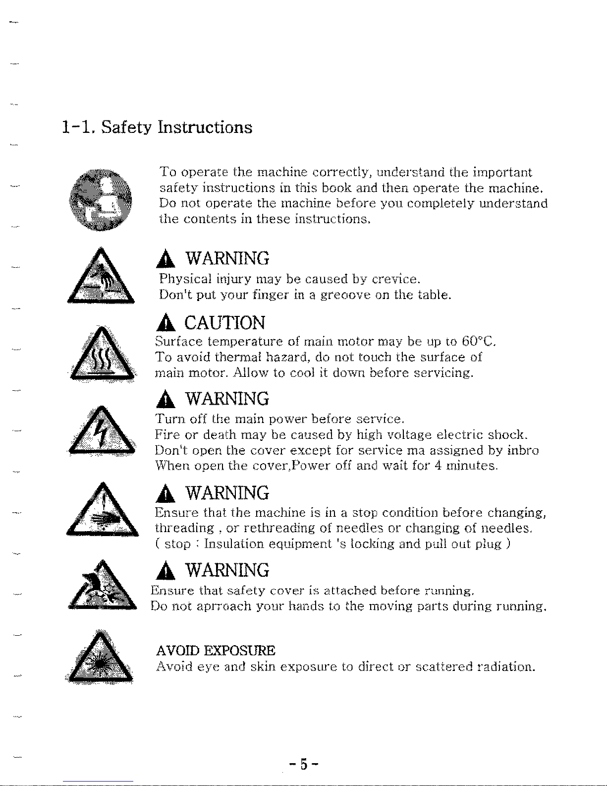
1-1.
Safety Instructions
To
operate
the
machine
correctty,
understand
(he
important
safety
instructions
in
this
book
and
then
operate
the
machine.
Do
not
operate
the
machine
before
you
completely
tmderstand
the
contents
in
these
instructions.
A
WARNING
Physical
injury
may
be
caused
by
crev'1ce.
Donlt
put
your
finger
in a
greoove
on
the
table.
A
CAUTION
Surface
temperature
of main motor may be up
to
60Q C.
To
avoid
thenna!
hazard,
do
not
touch
the
surface
of
main
motor.
Allow
to
coo] it down
before
servicing.
A
WARNING
Turn
off
the main
power
before
service.
Fire
or
death
may
be
caused
by
high
voltage
electric
shock.
Don't
open
the
cover
except
for
service
rna
assigned
by
inbra
Wben open
the
cover,Power off and watt for 4 minutes.
A
WARNING
Ensure
that
the
machine
is
in a
stop
condition
before
changing,
threading,
or
rethreading of
needles
or
changing of needles.
(
stop:
Insulation
equipment
IS locking
and
pull
out
piug )
A
WARNING
Ensure
that
safety
cover
i;:;
attached
before
running,
Do
nor
aprroach
your
hands
to
the
moving
parts
during funning.
AVOID
EXPOSURE
Avoid
eye
and
skin
exposure
to
direct
or
scattered
radiation.
-5-

OVERTURN
HAZARD
Do
not
place
the
machine
on
an
unstable
cart,
stand,
bracket
or
tab]e.
The
machine
may
fall,
causing
serious
injury to a
person,
and
serious
damage
to
the
1113chine.
A
machine
and
carl
combination
should
be
moved
with
care.
Qllick
stops,
excessive
force,
and
uneven
surface
may
cause
the
machine
and
cart
combination
to
overtur.
1-2.
WARNING SYMBOL
The
content
required a user's
special
caution
when
operating
the
machine
is
specified
as
the
warning
symbol
below.
;!,\ CAUTION
This
mark
means
dangerous
consequences
wiH
arise,
with
the
possibility
of
death
or
serious
injury
to
the
user,
if
the
embroidery
machine
is
handled
incorrectly.
A.
DANGER
This
mark
means
dangerolls
consequences
could
arise,
with
the
possibility
of
death
or
serious
injury to
the
user
ar:d/or
damage
to
the
embroidery
maehine
and facilities, if
the
embroidery
machine
is
handled
incorrectly.
/1"\
WARNING
This
mark
means
dangerous
consequences
may
arise,
with
the
possibility
of
somewhat
serious
injury
to
the
user
and/or
damage
to
the
embroidery
machine
and facilities, if
the
embroidery
m2chine
is
handled
incorrec\ly.
& LIGHTING EQUIIPMENT
Should
do
work
under
lighting.
-6-

1-3.
Stickers
Position
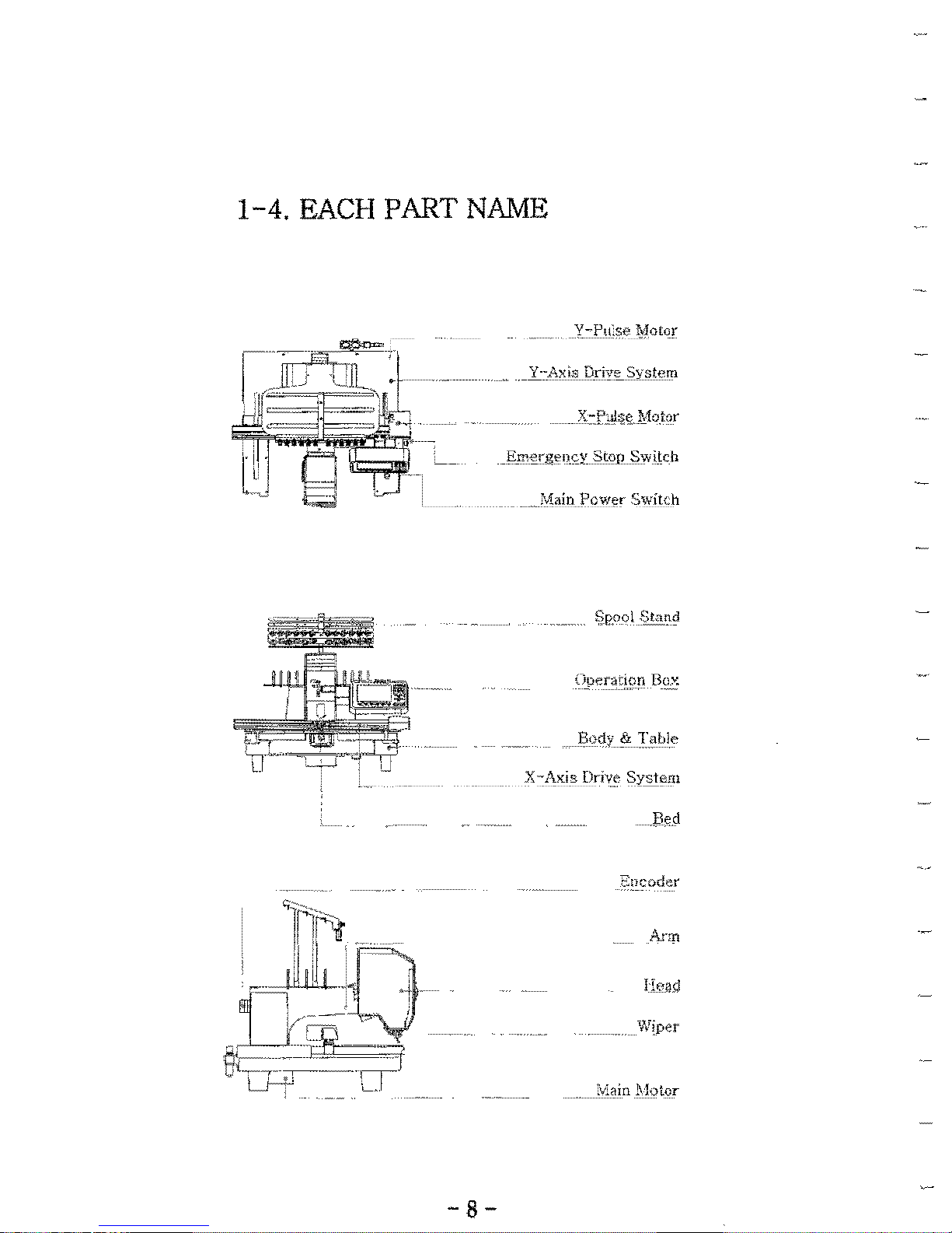
1-4.
EACH PART NAME
I
~
;\!Iain
Power
Switch
Operation
Box
l?ody
§z.
TaLle
encoder
VJjper
-8-
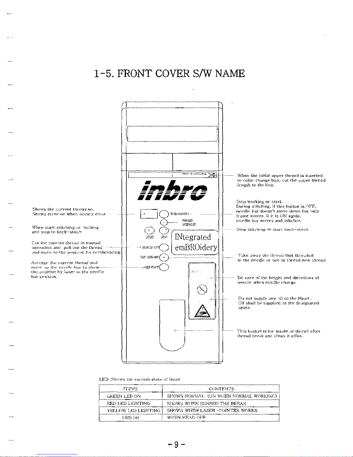
1-5.
FRONT COVER
8/W
NAME
Shows
til'"
c,,~rf'''t
t~n';n
'w,
Sh0','iU
e,r,.,t
<It",
whet~
()Cq'~$
;;-rr,A'
\Vh,·"
",ar,
stit,;hinz
'"
;m-hin,'I
ami
SI\)I'
to
b,w\(-"ti<c'l
C'm n,·:-
cmn'nllhtf;),;
in
ma""",i
nf>f'r>!l;""
M";
pull
em
th,"
tln'c'aJ
.",d
;-r,,,v,,
,,,
Hw
(NN.:·,n
f,;,'
r"-(t.r"'.H~~ng_
A''''fl,W
lL"
nm-cm
lhr",,,d
md
me""
~p
in",
F.r-",Ik
har
to
show
til"
(",,,ilion
by
:"SC]'
co
th"
n.;:,:r':"
b'l!"
p".,:.[on.
l
W1teh
(he
in!tial
"pret
lh.",,:!
is
j".~",(e:l
tn
"do:
ch:.ng"
box,
<:\tt
th&
<;;per
thtTll<J
knglh
!Q
Ihp
lin""
Swp
w[)rkirtg
Dr
~!srt.
During
s'lkh'!>".
if
tn'8
tn"rt""
is
nFP.
m-~",I)"
lnr do..
;m'l
moW-
,1<Iwn
bu,
"11;)1
frM!l~
I1hC1ve",;;
it
is
ON
"'>1"''',
mo",Ue
b.:r
m(>Y""
,md
slil{;h""
T
~k.:
,!\~~)'
01e:
(trp,,,:
Itmt
tkO',,:!n1
in
til'''
n"edk
G'
,-,~e
lO
t "-.,.,,,1
'ww
:':~fC¥.HL
n"
""re
a[
the
Iwight
und
tiir,-,eth,r>s
ef
n"'"":;,,
wtwn
r.""llt"
,'"a,-
&"
n"
m,( sum,ly
,my
"il
to
th<o
H~'"d
,
Oll
~h,.l!),,,
~'-'I-'I'LN\
;0
II'"
n""igIlflt"d
:>PG-ts.
'n-,:s
b~skH
I~
f"r
wa21
...
"I
Un ,,"a,l
u!\.('r
=--}",,,.d
\1r(',,1<
"tlr:
.:I"""
it
c!("".
-9-
2.
Carrying" the machine
Ll\
WARNING
This
machine
must
be
carried
out
only
by
the
man
who
is
familiar
with
safety
instructions and regulations.
The
following
instruclions
must
be
observed
when
carrying
L~e
machine
to
prevent
injury
an~
physical
damage
and
occurrence
of
mechanical
trouble.
When
tarrying
the
machine,
especially
setting
down
the
machine,
keep
up
the
level
of
the
machine
to
prevent
injury
and
mechanical
damage.
&21C
'th
hibman
r
WAR;<lNG
-.
arrymg
e mac
ne
y
powe
\,ftlhen
carrying
the
machine
by
human
power,
make
sure
to
wear
the
safety
shoes
and
seize
the
light
and
left
sides
of
the
machine.
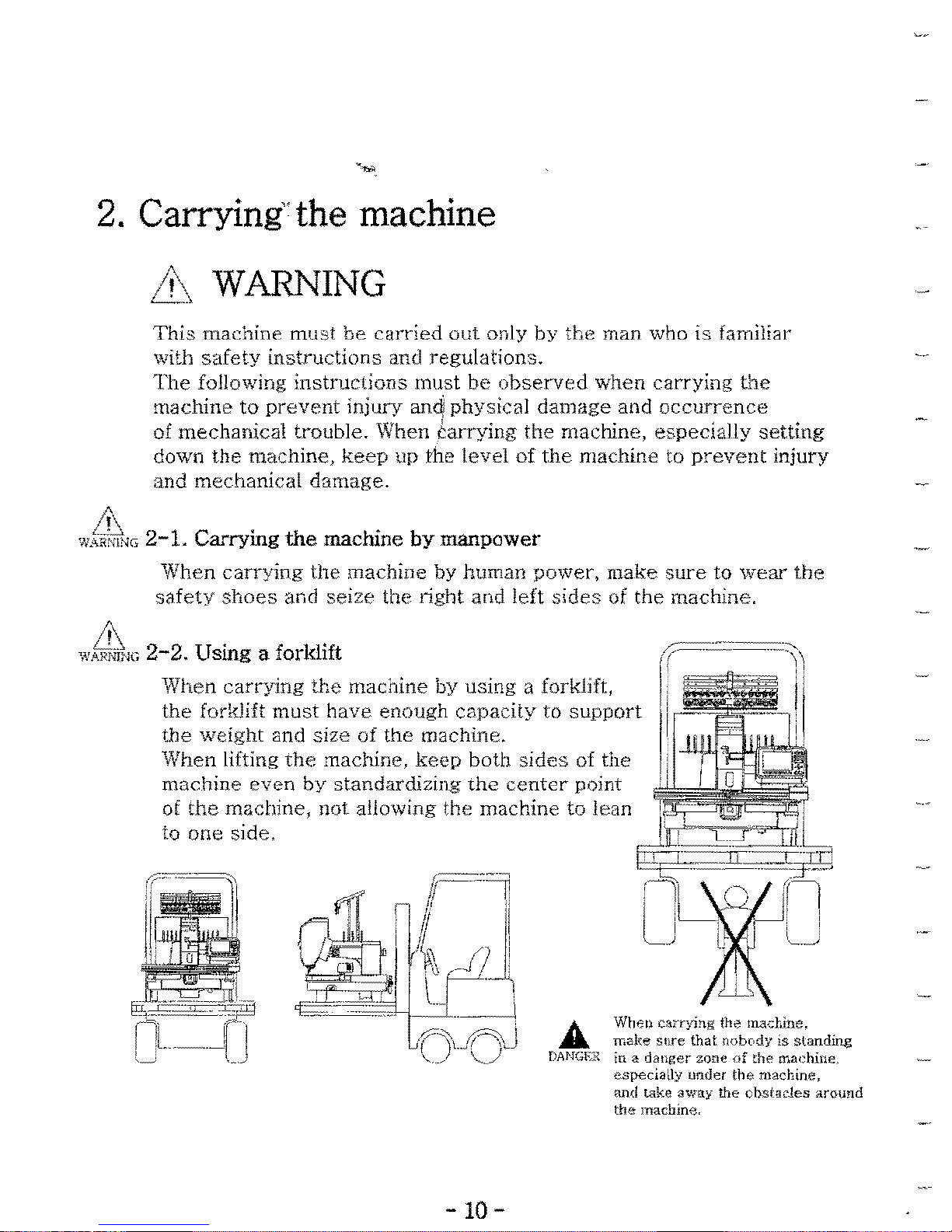
1\
w,~R;iiNG
2-2.
Using
a forklift
When
carrying
the
machine
by
using
a forklift,
the
forklift
must
have
enough
capacity
to
support
the
weight
and
size
of
the
machine.
When
lifting
the
machine,
keep
botb
sides
of
the
machine
even
by
standardizing
the
center
point
ot
the
machine,
not
allowing
the
machine
to
lean
to
one
side,
A
Wh€l~
canyjng
th0 mad-,inc.
rr.ake
SHe
that
nobody
is
standing
[lANGE:;:
in a danger zone
of
the machine,
especiaUy under the machine,
and
take
away
the
cbstades
around
the
machine,
-10-

3. INSTALLATION
AND
ASSEMBLY
&
CAUTION
When
installing
the
machine, follow
these
instructions
to
prevent
mechanical
damage
such
as
maUunction,
break
down,
etc.
or
physical injury,
A
DANGER
To
prevent
an
electrical
shock
caused
by a
short
circuit,
earth
the
ground
wire
of
the
machine
to the ground,
The
grounding
resistance
must be
100
ohms
II
or
less,
&
WARNING
Check
the
input
power
of
the
location
ior
installing
the
machine,
When installing
the
machine, do
not
change
arbitrarily
the
input
power,
'which
was
set
up at
the
factory. \Vhen a
user
changes
the
input
power
at will,
the
machine
may
cause
physical
damage
and/or
mechanical problems,
When
installing
the
power
cable, a
user
may
trip
OVer
the
cable,
therefore
install
the
cable
out
of
the
user's
working
space,
-11-
3-1.
INSTALLATION
ENVIRONMENT
L
The
machine
must
be
installed
on a
strong
floOf
that
can
bear
the
weight
of
the
machine
(marked
on
the
specifications)
sufficiently.
2. Do
not
install
the
machine
near
heat
sources
such
as
radiators,
heat
registers,
stoves.
or
other
appliances
that
produce
heat.
3. Install
the
machine
near
an
air
conditioning and
clean
up
the
machine
periodically,
as
dirt and
rust
may
cause
not
only
pollution
and
corrosion
of
the
machine
but
also
a fire and an
electric
shock,
4.
In
case
that
the
machine
is
exposed
to
direct
rays
of
light for a
long time,
it
may
cause
discoloration
and
transformation
of
the
machine. Install
the
machine
at
the
appropriate
place
away
from
direct
rays
of
light.
To
reduce
noise
of
operation,
complete
the
interior
work
of
the
factory
by
using
soundproofing
material
to
the
walls, ceiling and floor
inside
the
factory.
6.
Space
the
machine
at
least
50
em
from
the
left,
right
and
back
sides
of
the
machine
for
enough
mending
space
of
the
machine.
Ll\
3-2.
ELECTRIC
INSTALLATION ENVmONMENT
WA"NlNG
1. Input
Power
(adjusted
when
taking
out
of
the
factory)
:
Single
Phase
100V,llOV.120V,200V.220V,240V
(50/60Hz)
2. Approvable
voltage
range:
within ± 10%
of
rating voltage
,>.
Power
capacity
and
consumption
of
electricity: 450VA,
300W
4. Insulation
resistance:
more
than
lOMQ
(measured
by
500V
insdation
tester]
-12
-

&
3-3.
INSTALLATION ENVlROMENT FOR COMPRESSOR
"V?8NING
1.
NPUT
POWER :
llOv
, 220v l50/60Hz)
2.
APPROVED VOLTAGE
R,\NGE:
R,\TING VOLTAGE
±10%
3. STAND
SET
POSITION (FIG)
4. COMPRESSOR TUBE CONNECTION
Size:
8x5
, APPROX
1M
NOTICE : PlIt
the
marked A in
deeply
then
meet
the
pressure
of
air
with
,1,4
"4.5
Bar.
*
If
air leaks due
to
not complete insert.
Compressor
may be
overheated
or
abnormal working.
Make
compressor
automaticaHy
stop
at
the
pressure
point 5.5
bar
by using
aetomatic
pressure
adjuster.
(
if
the
pressure
drops around 4.5 bar.
compressor
3utomatica!iy works,)
Ill'
ill
CAUTION
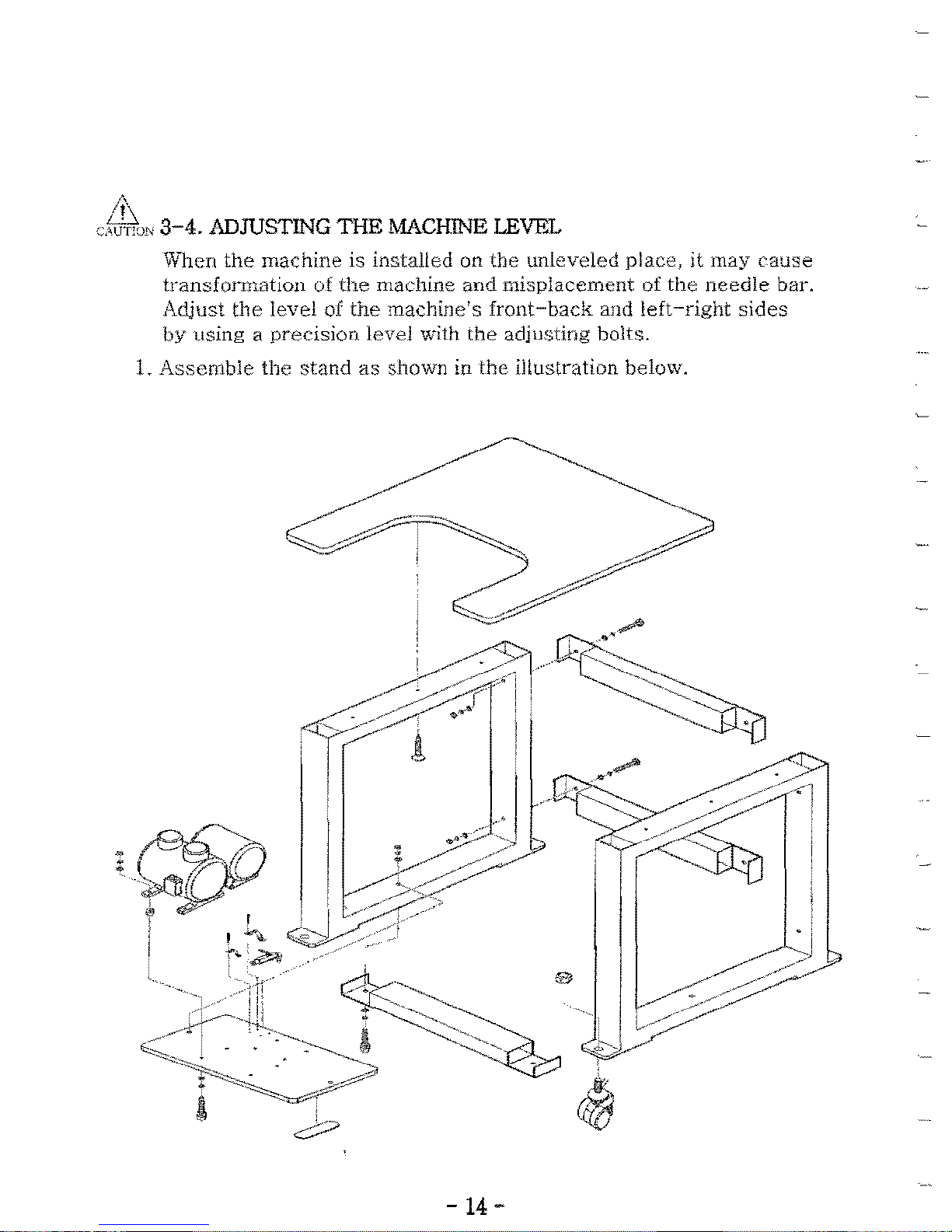
3-4.
ADJUSTING
THE
MACHINE LEVEL
Wilen
the
machine
is
installed
on
the
unleveled
place,
it
may
cause
transfonnation
of
the
machine
and
misplacement
of
the
needle
bar.
Adjust
the
level
of
the
machine's
front-back
and
left-right
sides
by
using a precision
level
with
the
adjusting
bolts,
L
Assemble
the
stand
as
shown
in
the
illustration
below,
•
·
•
-14
-
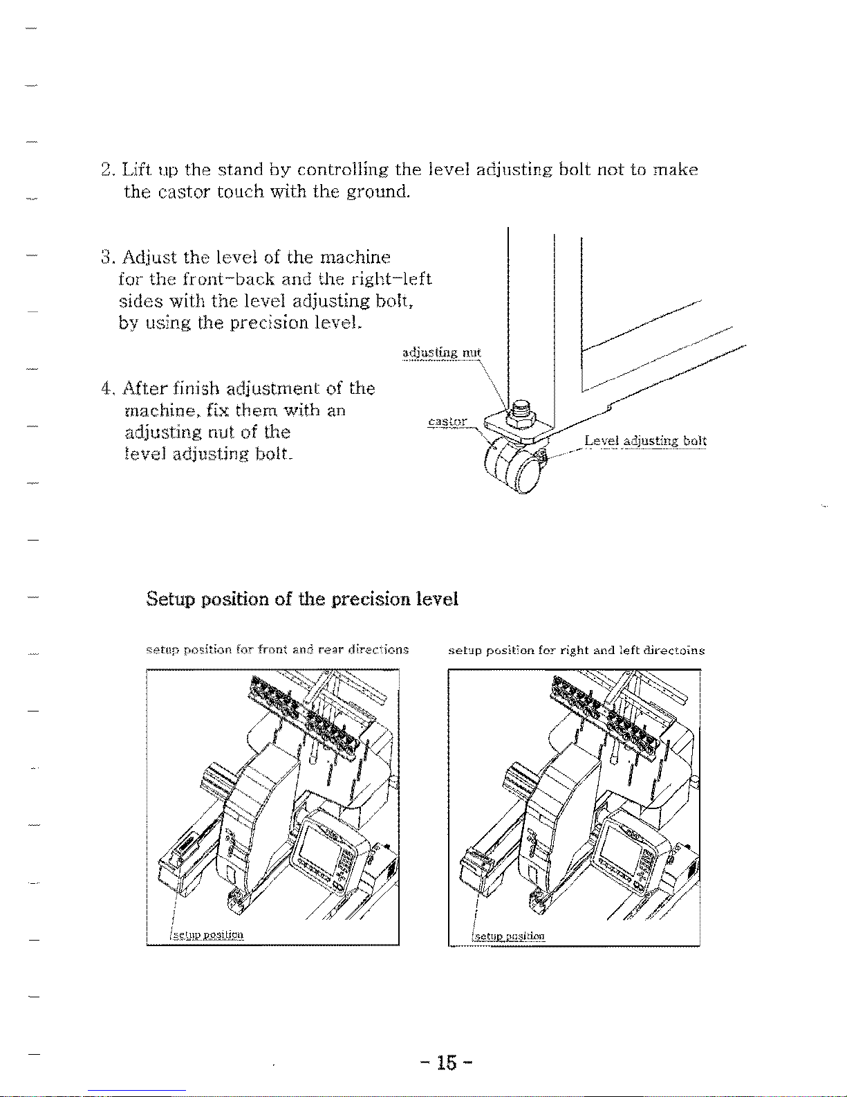
2,
Lift up the
stand
by
controlling
the
level adjusting bolt
not
to
make
the
castor
touch
with
the
ground,
3, Adjust
the
level of the machine
for
the
front-back
and the
right-left
sides
with
the
level adjusting bolt,
by using the
precision
leveL
adjusting nut
..
,
...
_._
..._....
- -
--"\
4,
After
finish
adjustment
of
the
\
"-
"?:;c=?
machine, fix
them
with an
castor
~-~~-~
adjusting nut of
the
"
_
Le':':t:~
,~djusting
bolt
level adjusting bolt.
Setup
position
of
the
precision
level
setu;:: position for front ano
fear
dir-ecions
setJp
pusifon
for
right
and
ieft
direcwins
"
-
15-
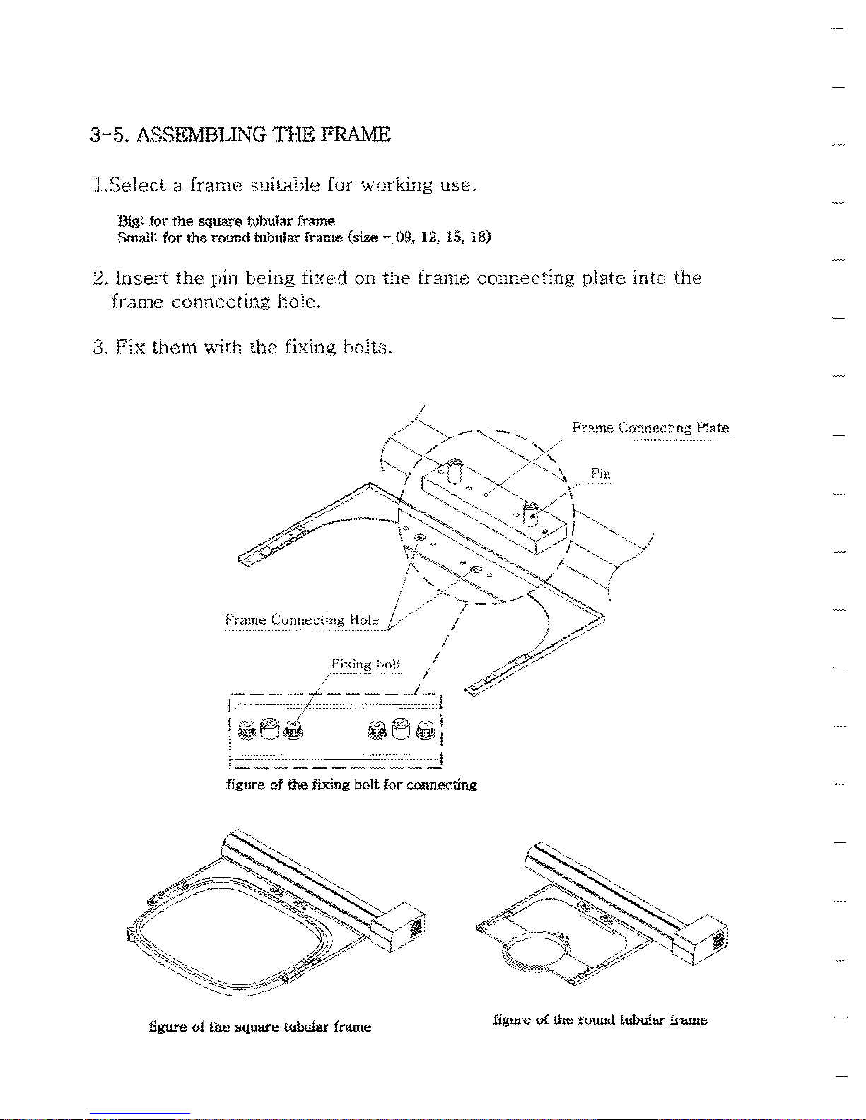
3-5.
ASSEMBLING
THE
FRAME
LSelect a frame
suitable
[or
working
use.
Big:
tor
the square tubular frame
Small:
for
the round tubular frame
(size
-.09.
12, 15, 18)
2.
Insert
the
pin
being
fixed
on
the
frame
connecting
plate
into
the
frame
connecling
hole.
3. Fix
them
\\~th
the
fixing bolts.
figure
Qf
the round tubular frame
figure
of
the square tubular frame
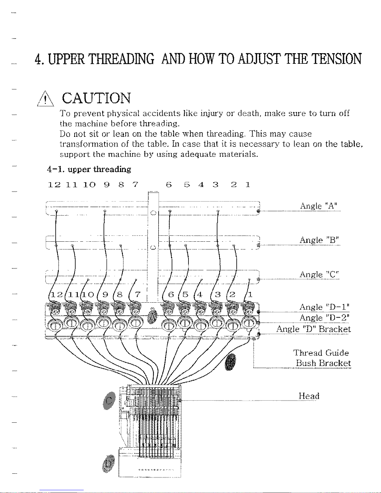
4.
UPPER
THREADING
AND
HOW
TO
ADmST
THE
TENSION
& CAUTION
To
prevent
physicat
accidents
like injury
or
death,
make
sure
to
turn
off
the
machine
before
threading.
Do not
sit
or
lean
on
the
table
when
threading.
This
may
cause
transformation
of
the
table. In
case
!hat
it
is
necessary
to
lean on
the
table,
support
the
machine
by
using
adequate
materials.
4-1.
upper threading
12
11
10
9 8 7
654321
p-=-
---------
-----1
-----------------,
,
'-;:------._-
_
..
_-
_
..
________
._
_. --•.
i Angle
ff
A
II
_______
0
_______
'" ----
------------
\--
-\
Ie
.',-
+'
-----\::-----:
---:
";~.----------~",
,.
l-tI0g1e
I'D-l
n
Anil:
1e
"[):::?"
Angle
"D"
Brack..et
Thread
Guide
~_!H,-"e
ad
,
i
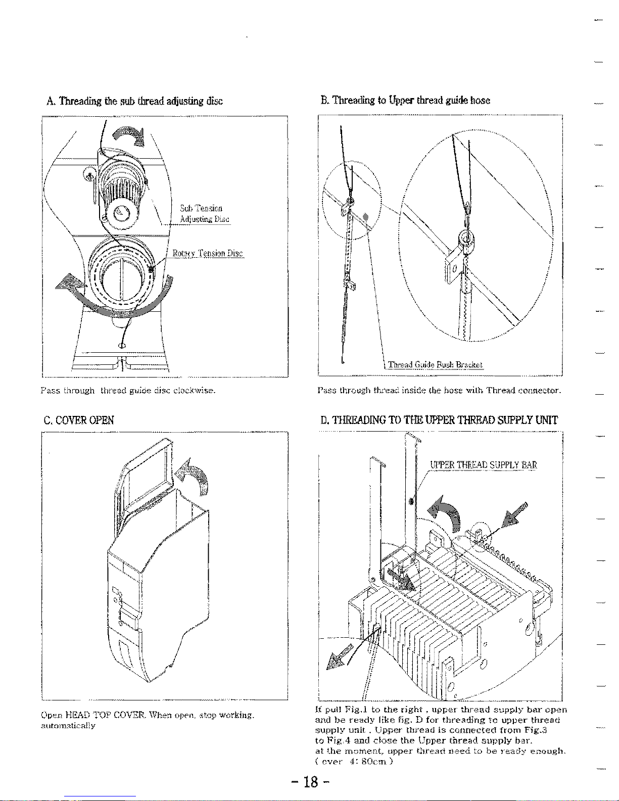
A,
Threading
the
IlUb
thread
adjusting
disc
B.
Threading
to
Upper
thread
guide
hose
,
I
3d)
--=-81;;lon
Atljsstill,i;
be
.1--
..
L
Pass
through tt.:"ea;;' insiG;;
the
hose
wilh
Thread
connector.
D,
TIlRllADlNG
TO
TIlE
UPPER
THllF.AD
SUPPLY
UNIT
UPPER
THRSA.t:
SliPPLY
EAR
?<1SS ::Jrough tlireuci
guiae
:ijs,~
c!oc]{wise.
C,
COVER
OPEN
r~~~~-~
I'
-
.-
-~---~-~
l\P"'Jl
HEAD
TOF
COV3:Ft
Whe-:l
open,
,ViJP
w(lrki:ng.
3UfOffi."Itic<iEy
18
-
E.
RUN
S!W
'THD.\JPIDOWN'
BUTTON
ON
THE
HEAD
FRONT
(Ref.
FIG
1-2)
u
'A,
If
YDU
don':
dc-se
the
upper
S1JPP~Y
bar
ftnd
button
'works,
('_'''Xr.:)1\!"
jt
rrwy be c;lused by ;ne<:hc.niol malfunction.
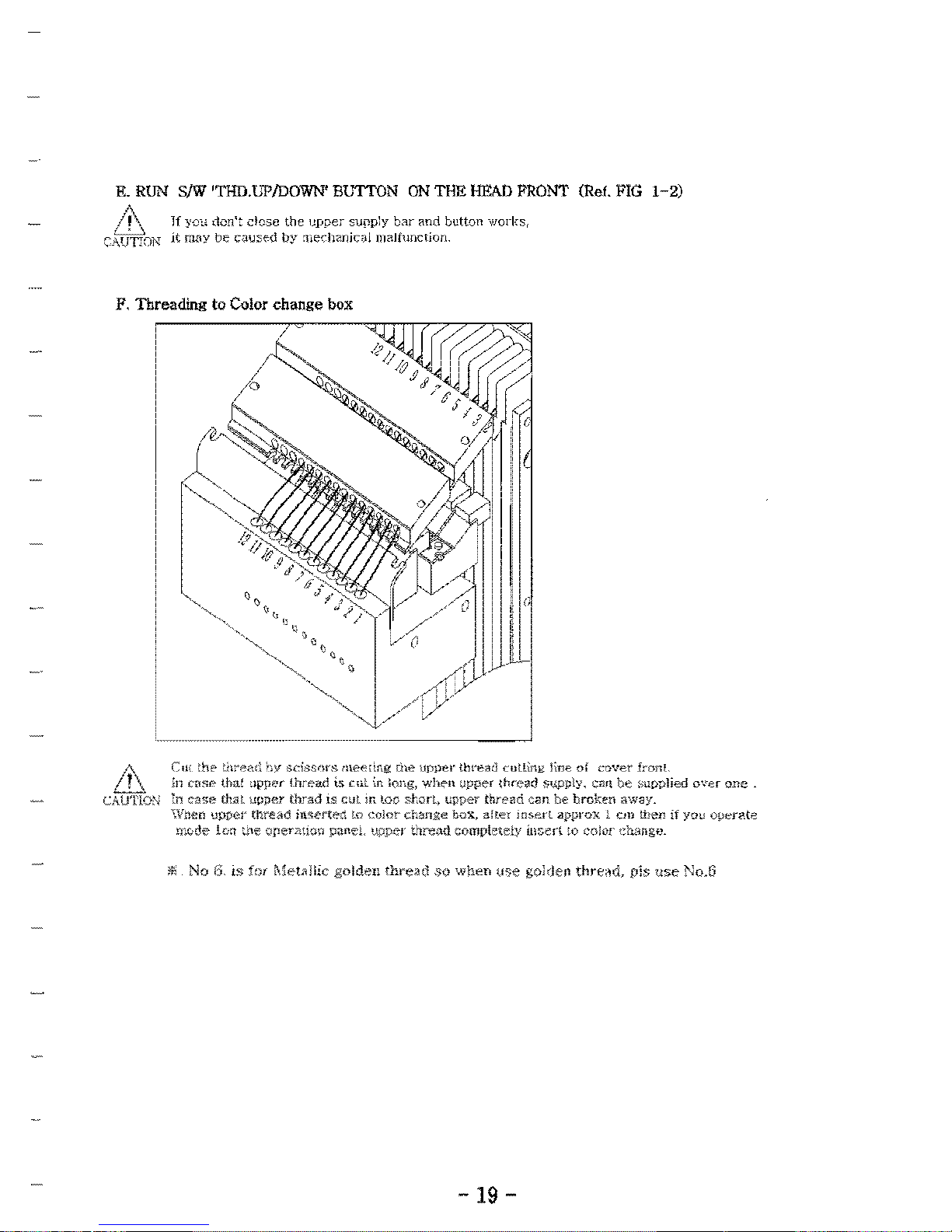
p,
Threading
to
Color
change
box
&
em
:hi"
:h:0dl
'lY "dSYlrs.
mee:mg
[he
upper
tiweaci
cuning
line
o!
cover
ironL
;n
(T'$i'
tha~
:Ipper
lhread
is
cuL
il1
long,
wht'lt
:;pper
,nn:;,lIj 5<JPply,
em\
be
supplied
over
one.
CAUTiON
:11
case
thill
upper
thrad
IS
cut
111.
loe
shon,
upper
thread
e<ln
be
broken
away.
\Vnctl
upper
thre;.d
iW'l:ertect
LO
eolor
change
bex,
alter
insert
;approx i
em
lhen
if
you
0pen'.te
rL.0Ce
10:;
~"f'
Qperl!tl(i\) paneL upper thre;;td completely Loserl to
color
dunge.
-19
-
 Loading...