


ASSEMBLY INSTRUCTIONS
2 DRAWER CPU STAND
PAGE 1 OF 7

ASSEMBLY INSTRUCTIONS
ASSEMBLY TIME
PARTS IDENTIFICATION
60 MINUTES
ASSEMBLY TIPS:
1. Remove hardware from box and sort by size.
2. Please check to see that all hardware and parts are present prior to start of assembly.
3. Please follow attached instructions in the same sequence as numbered to assure fast & easy assembly.
WARNING!
1. Don’t attempt to repair or modify parts that are broken or defective. Please contact the store immediately.
2. This product is for home use only and not intended for commercial establishments.
NOTE:
Phillips head screw driver is required in the assembly process; however, manufacturer does not provide this item.
A
PAN EL
LEFT SIDE
RIGHT SIDE
B
C
D BOTTO M PANE L
E TOP PAN EL
PAN EL
MIDDLE DIVIDER
PAN EL
1 PC
1 PC
1 PC
1 PC
1 PC
G
H
I
J
K
DRAWER
FRONT PANEL
DRAWER BACK
PAN EL
LEFT DRAWER
SIDE PANEL
RIGHT DRAWER
SIDE PANEL
DRAWER
BOTTO M PANE L
2 PCS
2 PCS
2 PCS
2 PCS
2 PCS
F BACK PANEL
Z
NO DESCRIPTION FIGURE Q’TY
1 GLUE 40g
WOODEN DOWEL
2
Ø 8x30mm
HARDWARE IDENTIFICATION
1 PC
1 PC
26 PCS
PAGE 2 OF 7
NO DESCRIPTION FIGURE Q’TY
3
4
SCREW
Ø 4.5x42mm
CAM LOCK
Ø 15x12mm
6 PCS
10 PCS

Z
HARDWARE IDENTIFICATION
NO DESCRIPTION FIGURE Q’TY
5
6
7
8
9
CA M BOLT
Ø 7x35.5mm
RAIL
L = 270mm
SCREW
Ø 3x12mm
LOCK CASTER
Ø 50mm
CASTER
Ø 50mm
CL
CR
DL
DR
10 PCS
2 SET
24 PCS
2 PCS
2 PCS
Z6,Z8,Z9,Z10 not included in blister packaging.
NO DESCRIPTION FIGURE Q’TY
10
11
12
13
14
SCREW
Ø 4.8x16mm
HANDLE
L=50mm
BOLT
Ø 4x21.5 mm
SCREW
Ø 4.2x35mm
STICKER
Ø 20mm
16 PCS
2 PCS
4 PCS
8 PCS
2 PCS
STEP 1
5 x6
4 x2
1
4
2
5
5
2
5
E
5
5
2
A
2
2
2 x6
The Glue (1) should be used in the indicated
locations to help solidify the assembled unit.
NOTE:
Phillips head screw driver is required in the assembly process; however, manufacturer does not provide this item.
PAGE 3 OF 7
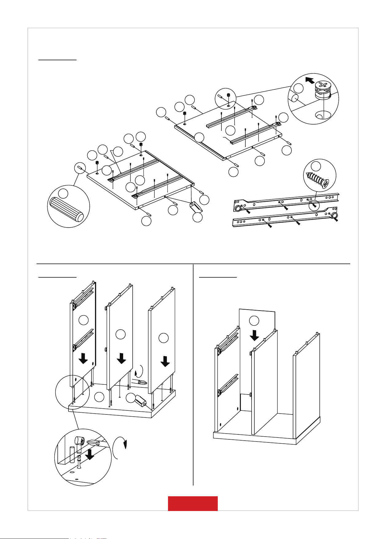
STEP 2
4 x4
2 x12
STEP 3
2
4
2
B
4
2
2
4
6 (CL)
7
C
7
2
2
6 (CR)
2
2
1
7
7
2
2
7 x6
STEP 4
B
E
C
F
A
1
PAGE 4 OF 7

STEP 5
3 x6
1
3
3
D
3
3
STEP 6
10
9 x2
8
10
8 x2
9
PAGE 5 OF 7

STEP 7
13 x4
12 x2
11 x1
13
4
2
2 x4
I
2
1
H
J
4 x2
7 x6
6 (DR)
13
13
1
5
G
5 x2
K
6 (DR)
6 (DL)
STEP 8
COMPLETE
4
14x10
6 (DL)
G
G
PAGE 6 OF 7

215mm(8.25")
450mm(17.5")
450mm(17.5")
450mm(17.5")
575mm(22.5")
219mm(8.5")
209mm(8")
Note : Dimension tolerance ±5%
130mm(5")
334mm(13")
129mm(5")
PAGE 7 OF 7
 Loading...