

Inbeca MF 30 AS, MF 30 WS, MF 22, MF 30, MF 41 Operation And Maintenance Manual
...

Technical Specifications:
- Function Limitations …….. ............................................................. 1
- Production capacity……… ............................................................. 1
- Dimensions .................................................................................... 2
- General Features ........................................................................... 2
General information and installation:
- Introduction .................................................................................... 3
- Unpackaging and inspection........................................................... 3
- Location and levelling….................................................................. 4
- Electrical connection ...................................................................... 4
- Drain and water connexions.. ........................................................ 4
Operation instructions
- Start-up…………….......................................................................... 5
- Verifying operation with the equipment working………………........ 5
Operation principle
- Water circuit….. ............................................................................. 7
- Cooling circuit…… ........................................................................ 8
- Components description……. ...................................................... 11
INDE
X
Process of adjusting, elimination and substitution of
components…............................................................................. 14
Electrical diagram ..................................................................... 19
Troubleshooting … .................................................................... 20
Diagnosis service....................................................................... 21
Cleaning and maintenance instructions
- General ........................................................................................ 22
- Cleaning the ice making equipment……...................................... 22
- Instructions for cleaning the water circuit………… ...................... 23
Control Panel ……..................................................................... 25
Components of Ice making equipment…............................. 26
Type of installation
- Installation in an adjacent room… ............................................... 28
- Installation in a false ceiling….. ................................................... 29
- Ice fountain semiannual maintenance
….. .................................. 30
TECHNICAL SPECIFICATIONS
MODULAR ELECTRONIC ICE EQUIPMENT
mod. GEL-MF 30
¾ OPERATION LIMITS
MIN MAX
Environmental temperature
10º C 40º C
Water temperature
5º C 35º C
Water pressure
1 bar 5 bares
Variation with regard to plate tension
-10% 10%
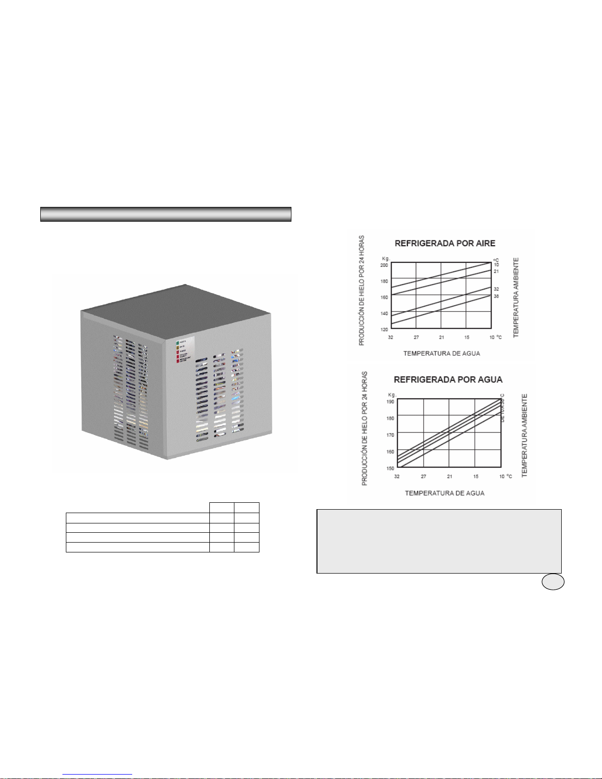
¾ PRODUCTION CAPACITY
NOTE: The daily production capacity change when the environmental
temperature and the water supply change, a capacidad de producción
diaria varía al variar la temperatura ambiente y del agua de alimentación
, thus the space around the equipment..
So as to mantain the equipment in maximum efficient conditions, it is
necessary to do the periodic maintenance as explained in the
correspondence part of the manual
1
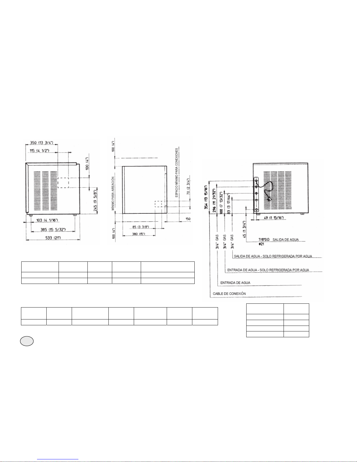
¾ DIMENSIONS OF THE EQUIPMENT
High (Whitout
base)
525 mm
High (with base)
542 mm
Wide
560 mm
Deep
533 mm
Weight
49 Kg.
¾ MF – 30 GENERAL FEATURES
Model Cooling Material Compr. CV
Water consumption (l/24
HR)
MF 30 AS Air Stainless 3/4 200
MF 30 WS Water Steel 3/4 850 *
Ampere Electrical cons. Cable Fuse
Tension Amperes Start-up Power Kw h by 24 HR Section Amperes
230 / 50 / 1 4 20 760 W 17 3 x 1 mm 2 10
* To 15º C of water temperature
2
¾ INTRODUCTION
¾
This operation manual has been writing to give the technical
specifications as well as all the instalation instructions, start-up,
operation, maintenance and cleaning the modular equipment of ice
crusher and super ice crusher of MF electronic range.
The electronic equipment of ice crusher and super ice crusher has been
designed and manufactured with high quality level.
The equipment is tested during several hours and reassure a maximum
performance in whatever use and situation.
2. Check the external cartoon packaging and the wood platform used for the
delivery. Whatever obvious damage in the external packaging has to be notify
to the transport; in this case check the equipment with a representative of the
transport agency.
3. a) Cut and take out the plastic ribbons that mantain seale the cartoon
packaging.
b) Take out the cramps that fix the cartoon in the platform.
c) Open the upper side of the packaging and take out the V
protective angular plate
d) Lift the cartoon taking it out of the equipment.
4. In models MF 22, MF 30, MF 41 Y MF 51 take out frontal panel / saque el
frontal / top panel , while in model MF 61 take out top and lateral panels and
check the unit so as to verify it has not been damage during transport.
5. Take out the inner supports used for the transport as well as adhesive
ribbons.
6. Check the pipe of the cooling circuit do not graze between them and it do
not touch other pipes or surfaces; make sure the fan spin freely.
7. Check the compressor it is free of swing above their own shock absorbers..
8. Observe the details of the plate located in the back part of the frame near
the water and electrical connexions and check that the voltage of the electric
net it is suitable for the equipment.
ATTENTION: A wrong voltage of electric supply will cancel
automatically the warranty.
9. Fill in the warranty coupon located inside the User manual, refer to the
model and the serial number of the unit located in the plate fixed to the frame.
Send the coupon to your local distributor.
INSTALLATION AND GENERAL INFORMATION
NOTA: It is recommended when making the installation and the maintenance
operation, follow this manual so as not to damage or reduce the quality and
security characteristics of the equipment.
- Store of ice
The equipment model MF do not have pile ice dispenser basin, thus it is
necessary to design and build one with the material most suitable according
the the decoration of the room. Having into account the following points:
The high of the basin has to be between 90 and 100 cm to make easy the
pick up of the ice.
The dimensions of the ice dispenser has to be approximately of 60 cm wide
x60 cm deep x20 cm high.
It has to have a drain to throw away the ice.
¾ UNPACKAGING AND INSPECTION
- Ice equipment
1. Ask the assistance of the official distributor for a correct installation.
3
Before connecting the ice equipment with the electric line, check the ampère
again of the unit, detail in the plate, with the correspondent ampère of the
electric supply.
¾ WATER AND DRAIN CONNEXION
- General
When choosing the water line for the modular crush and supercrush ice
equipment of model MF take care of the following: la serie MF,
a) Length of the line
b) Clear and pure water
c) Suitable pressure of the line.
¾ LOCATION AND LEVELLING
Water is the most simple and important ingredient for making ice, for this
resason the previous points are very important. A low pressure of water,
below 1 bar can origin problem with the operation of the unit.
Water that contains and excess of minerals can produce a residuum sheet
in the inner parts of the water system, meanwhile a soft water containing
lower mineral salts produce a granular ice too “dry”.
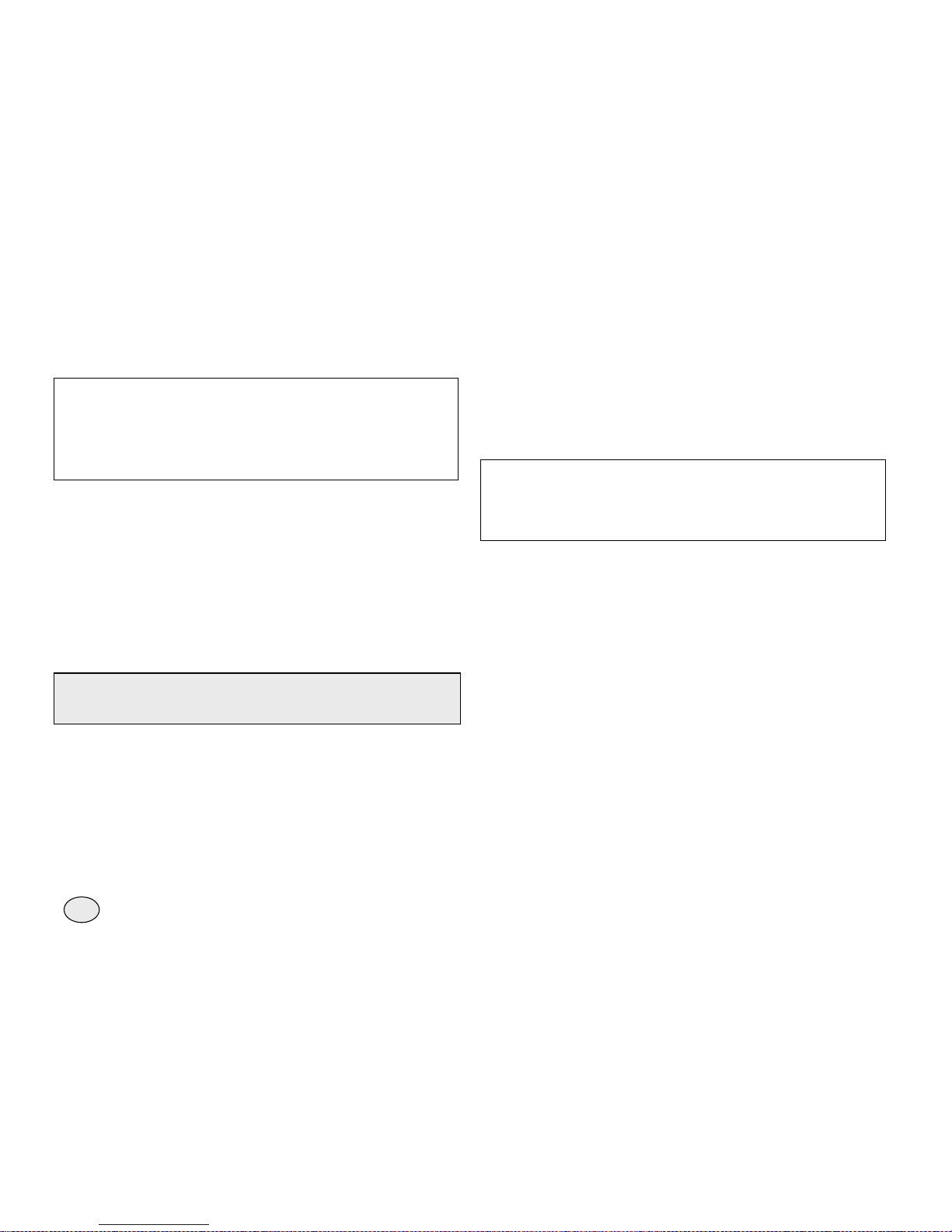
ATTENTION: this ice equipment has been designed to be installed in
areas where the room temperature do no exceed the maximum of 40 º C
nor the minimum of 10 º C
Prolonged period of operation with temperature different ot the
mentioned represents a wrong use of the equipment and suppose the
nullity of the guarantee.
¾ ELECTRICAL CONNEXIONS
To choose the kind and section of the cable observe the ampère indicated in
the plate of the equipment.
All the equipments has an electric supply cable, so it is needed a conection
to the electric line equipped with earth cable and with magnetothermic
switch with fuse appropriate as it is indicated in the plate of each equipment.
The maximum ampere variation permitted does not have to exceed a 10%
of the plate or be less than a 10% of the same.
A lower ampère can produce an anomalous operation and make damage
seriously the protection device and the electric winding.
NOTE: All the external connexions has to be perfect, according with the local
laws. In some cases it is needed the intervention of a qualified electrician..
A
TTENTION: Using soft water (lower mineral salt) with less electric
conductivity of 30 mS don’t let the low tension electricity to go
through between the sensors of water level, causing the stop or wrong
function of the unit.
Chlorine water or ironish water can be partially improve with active coal
filters.
- Inlet of water
Connect the male connector to the water inlet of 3/4" Gas to the water line
using a reinforced plastic pipe with non-polsonous material for food or a
copper pie with external diameter of 3/8".
The inlet water line has to have a stopcock located in an accessible place
near the unit. If water has a high level of impirites it is recommended to install
a fitler or a purifier to prepare it appropriately.
- Water inlet – Water cooling models
The models cooled with water need two separate inlet lines; one for the tank
and the other one has to go through one adjustment mechanic valve to the
cooling condenser.
Also for the water connection of the condenser use a reinforced plastic
flexible pipe or a copper pipe of 3/ 8 with female connector of+" Gas and a
separet bypass valve.
4
¾ CHECKING THE PERFORMANCE WITH THE UNIT WORKING
D. Take out the front panel and if it is needed put the high and low pressure
gauge in their corresponding tyre valve to check the condensation and air
intake pressure.
- Drain
It is recommended a rigid plastic pipe with internal diameter of 18 mm and
constant flow of 3 cm per meter. The draining of remainder water it is made
by gravity; it is necessary a drianing with vertical air inlet near the connector
and that it go to the open siphon for a constant flow.
- Drain – Model cooled with water
The equipment cooled with water need a new line of drain separet with a
male connector 3/4" Gas that comes with the indication “Drain- Only for
cooled with water".
C. After the compressor work 2 or 3 minutes, check that the ice go out
through the unloading hole and through the pipe go to the store.
NOTE: All the water connections has to be perfect and realise according to
the local laws. In some cases it is necessary the intervention of a qualified
plumber.
¾ STARTING
A
fter a correct electrical, water and drain installation, follow the next
instructions for the starting up:
A. Open the tap and connect the plug or electric general switch located in the
electrical connexion line. The first GREEN LIGHT will light, showing the unit
is under tension.
OPERATION INSTRUCTIONS
NOTE: When the unit has been some time disconnected, the RED LIGHT
it is flashing during 3 minutes; afther these minutes it will start the motor ot
the gear reduction and after 5 seconds the compresor.
B. After the 3 minutes, the unit will start up activating the
following components:
- MOTOR / S REDUCTION GEAR COMPRESSOR
- MOTOR / S OF FAN(if the unit is cooling with air), controled by the
temperature sensor of the condenser located in the wings of the same.
NOTE. The first ice granule present a scarce consistence because the
temperature of evaporation still have to reach the normal functioning
value. Wait 10 minutes so as the evaporation temperature go down to
the normal functioning values so as the ice has the correct consistence.
NOTE. If after 10 minutes of being working the equipment the
temperature of the evaporator has not reach below 1°C due to an
inadequate quantity of cooler, the temperature sensor of the evaporator
detects this abnormal situation and consequently stop the unit. In this
circumstance, the YELLOW LIGHT switch on.
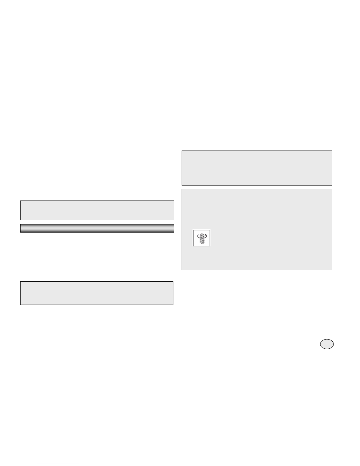
After diagnosing and eliminating the problem of this poor
evaporation temperature due to inadequate quantity of
cooler or excessive condensation temperature, press the
boton RESET located in the lid of the control
After 3 minutes, with the RED LIGHT flashing, the unit will start working.
5
F. Check the correct function of ice level control electronic eyes, put the
hand between the two sensor located in the outlet pipe. (one in every
pipe in model MF61). In this way it is interrumped the beam and switch
off the RED LIGHT located in the front side of the electroic
Card. After 6 second the unit stops automatically and switch
On the YELLOW LIGHT showing the situation FULL CABIN.
The beam of light is retablished after 6 seconds, the unit will start up
Automatically (after de 3 minutes of delay) and the yellow
Light that has been switched on before.
NOTE: in the air cooled models, the condensation pressure remain
between two values preestablished throught the fan, sending
intermittently through the sensor located in the wings’ condenser.
If the condensation temperature reach to 70 º C due to
and obstruction in the condenser and/or the motor of the
fan do not work, the sensor temperature of the condenser
stop the unit and consequently a RED LIGHT of danger is
switch on.
After diagnosing and solving the problem, repit the operation indicated in
the previous “Note” to start up again the unit.
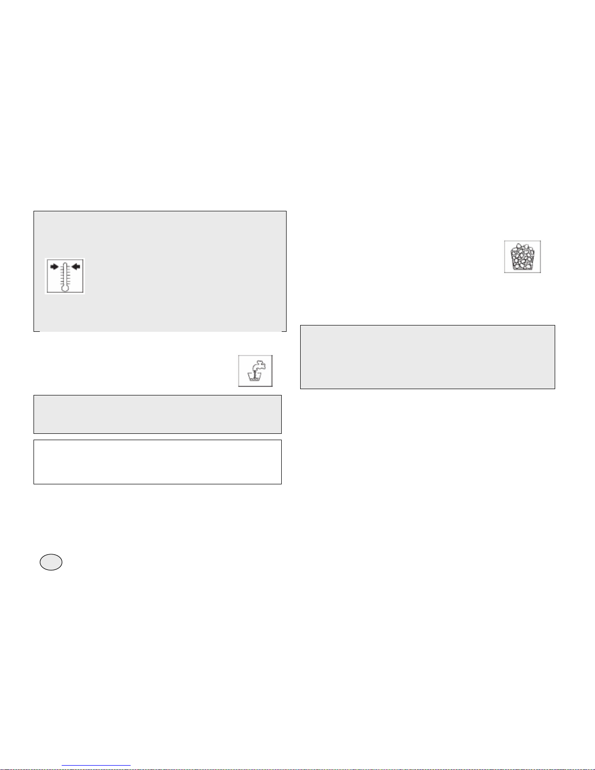
E. Check the correct functioning of the water level sensor, close the
stopcock. After some minutes when the level of water
Go down the sensor, the unit will stop and inmediately
switch on the YELLOW LIGHT showing the lack of water.
NOTE: The water level sensor detects the presence of inadequate quantity
of water in the tank and it confirms it to the microprocessor manintining an
electric low ampère flow through the sensors using the water as a
conductive material.
ATTENTION. To use demineralize water (water whitout or with little
salt) with a electric conductivity of less than 30 mS not allow the
lower tension electricity to pass making the unit to stop or not
functioning, a YELLOW LIGHT swith one showing a lack of water.
After open again the stopcock, the YELLOW LIGHT switch off automatically
and a RED LIGHT is flashing. After 3 minutes the unit start up again, first
the reduction gear and after 5 seconds the compresor.
NOTE. The control level of the ice (infrared system) is independent of the
temperature, otherwise it can be affected for the external light and the dirty or
lime deposits located directly in the eyes(infrared sensors).
For a correct operation of the unit it necessary to install it far away of direct
point of light and to scrupulously observe the points mentioned in the
maintenance of the eyesde los ojos.
G. If they are instaled take out the auxiliar manometers and install again the
frontal panel that have been taken before.
H. Explain to the owner the function of the ice equipment as well as the
cleaning and maintenance of the same.
6
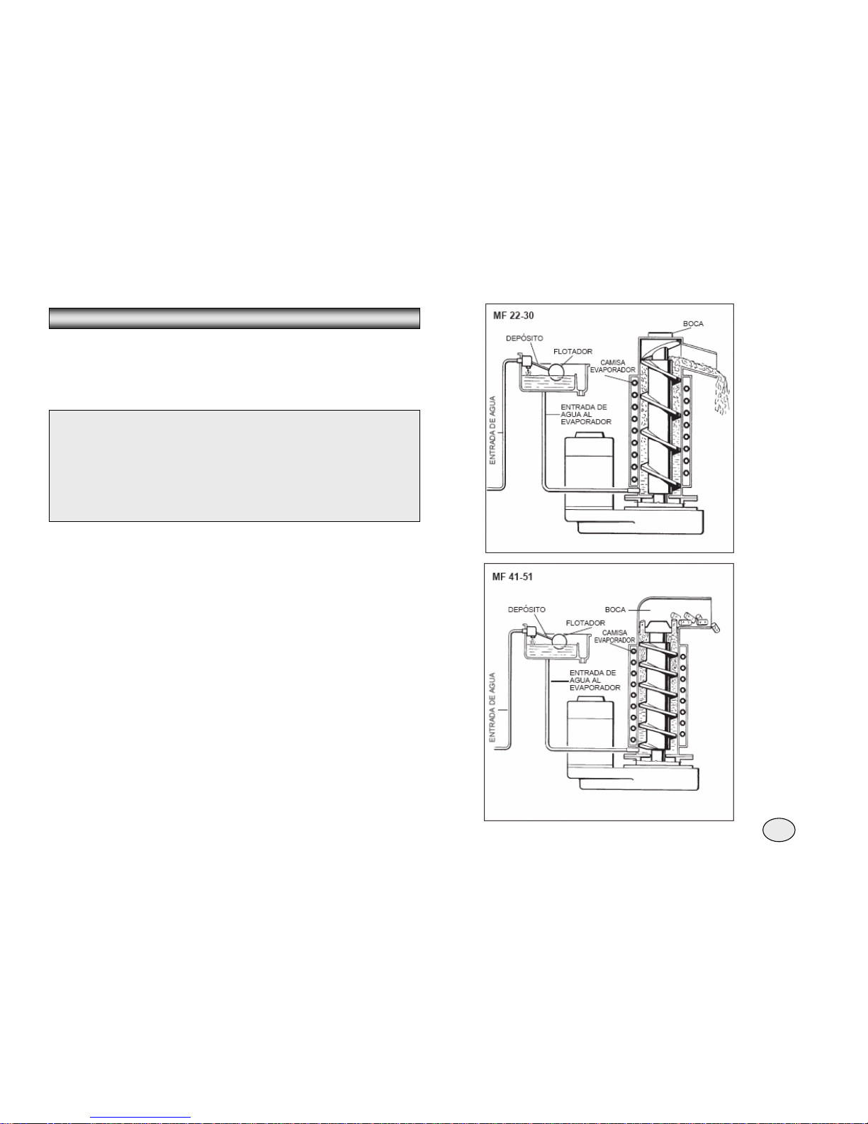
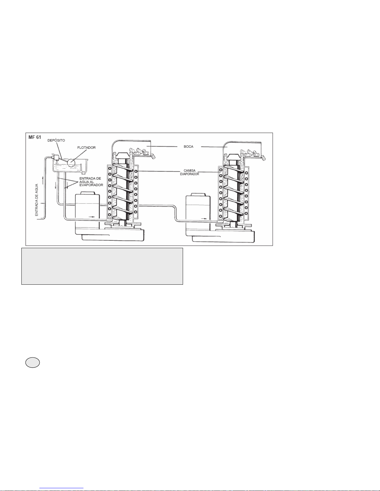
¾ WATER CIRCUIT
Water enter into the machine by the inlet line, where there is a small arille filer
located in the back side and here reach the wáter tank going through a float
valve.
PRINCIPLE OF OPERATION
NOTE: The presence of water in the tank is detected by a system of two
sensors that work together with the electronic board. Both sensors use the
water as a conductive to maintain a electric flow of low voltage that it is send
to the electronic board showing the presence of water in the tank. The lack of
water or the presence of soft water with an electrical conductivity with less of
30mS (demineralize waters)means the interruption of electrical flow to the
electronic boards and consequently the stop of the unit and the switch on of
the YELLOW LIGHT of ” lack of water”.
Tank of wáter is located allied of the evaporator case to a high that allows
through the communicative pipes, maintain constantly a correct level of
wáter inside the evaporator case.
Water enters from the tank through the conexion pipe inside the
evaporator case, where it is unfreeze and it is transformed in ice; this is
constantly mantained in movement by a stainless steel shaft that turn
inside the evaporator case.
The shaft, sumerge in water inside the evaporator turn in antitimetable
direction by the action of a reductive motor, pushing up the sheet of ice
that is formed in the internal cooled walls of the evaportor.
The ice, when it is push up by the shaft becomes more thick and when it
reach the crush it is compacted and cut into pieces, going through the outlet
pipe and falling into the ice keeper.
When the unit start up, it start up the continuous process of ice making,
process that continue until the ice keeper is full until the level sensors located
in the pipe of outlet ice.
When the ice interrumps the infrared beam of light between both electronic
eyes ( one or both in the model MF 61), the unit stops, the YELLOW LIGHT
switch on that shows the situation of full cabin.
7
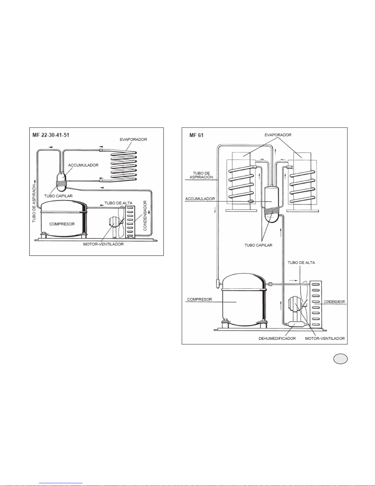
The liquid circuit lead the
refrigerant from the condenser
to the capillary tube through a
dehydrated filter.
When the refrigerant in liquid state
goes through the capillary tube
lose gradually a part of pressure
and a part of temperature.
Then it reachs and enter in the coil
evaporator. Water in contact with
the cooled walls of the evaporator
give heat to the refrigerant that
flow inside the coil, making its
evaporation and the consequent
change of liquid state into steam.
The regrigerant in steam state after
going through the accumulator it is
suck in again in the compressor
trhough the aspiration line.
NOTE: The interruption of the beam between the sensors is inmediately
showed by the switch off of the RED LIGHT located in the electronic board.
Afther the interrumption of the beam of light during 6 seconds, the unit stops
and the YELLOW LIGHT switch on. The 6 seconds of delay protect the unit
of unnecessary stops due to the eventual interruption of the beam of light,
that can be produced for the fall of the ice through the pipe.
When the ice is taken out of the store cabin and the outlet pipe get free, the
beam of light between the two sensors is inmediately reestablished and the
RED LIGHT is switch on in the centre of the board. After 6 seconds the unit
start up again, the YELLOW LIGHT of full cabin switch off and after 2-3
seconds the ice fall again through the pipe.
¾ COOLING CIRCUIT
The refrigerant in gaseous state and high temperature it is pumped from the
compressor, going through the condenser and it is transformed in regrigerant
in liquid state.
The pressure of push of the refrigerant system (high pressure) it is mantained
between the previously establish values (8/9 bar for MF 22 and 17/18 bar for
MF30, MF 41, MF 51 Y MF 61) through the temperature sensor of the
condenser that has the probe located inside the sheet of the condenser, in th
e
air cooled models.
This sensor notice the increase of temperature in the condenser above the
established limit, change its electric resistance and send low tension electricit
y
to the MICROPROCESSOR of the electronic board that supply through a triac
the fan motor in intermittend way ON – OFF.
8
In water cooled models, the high pressure of the system is constant
to 8.5 bar in model MF 22, and to 17 bar in models MF 30, MF 41, MF
51 Y MF 61, due to a quantity of water that goes through the
condenser, which flow is controled by the action of the presostate
valve that it is open to increase the water flow that cool the
condenser.
9
NOTE, In case the temperature sensor of the condenser detects 70ac ' in the
cooled air model or 62º Cin the water cooled version for one of these
reasons:
- DIRTLY CONDENSER (cooled by air)
- INADEQUATE CONDENSATION WATER (cooled by water)
- BURNT FAN OR STOPPED (cooled by air)
- HIGH ROOM TEMPERATURE (UP TO 43° C)
the unit stop inmediately so as to prevent to be working in extremely
abnormal and dangerous situation. When this happens it switch on the RED
LIGHT,that warn of high temperature.
After eliminating the cause of excessive temperature in the condenser,
push button RE-SET.
The RED LIGHT will flash and after 3 minutes the unit will start working. The
temperature sensor of the condenser has also another option for security, it
consist in preventing the start up of the unit if the room temperature (detected
by the sensor of the condenser) in where it is installed the unit is less than 10
C.
When the room temperature is up to 10º C, the electronic board start up
again the unit automatically after 3 minutes.
The pressure of air intake or low pressure in normal conditions is of 0.5 bar in
model MF 22 and 2.4+2.6 bar in model MF 31, MF 41, MF 51 Y MF 61 after
some minutes of operation. These valuer can change between 0.1 bar or 1.2
bar, in relation with the water temperature that supply the evaporator.
NOTE If after 10 minutes of operation not produce ice and the tempertaure
registered by the sensors of the evaporator do not reach -1 C, the unit stops
and switch on flashing the 5
th
YELLOW LIGHT
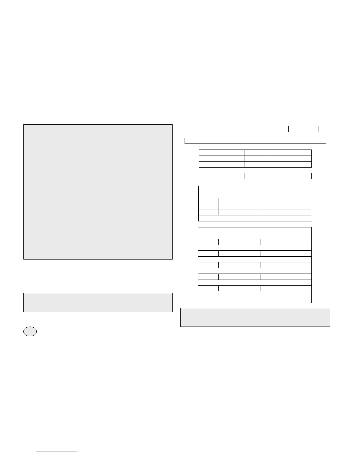
COOLING EXPANSION DEVISE:
Capillary pipe
PRESSURE OF OPERATION (With a room temperature of 21º)
Pressure of impuls: MF - 22 MF 30 - 41 - 51 - 61
Cooling by air 8 / 9 bar 17 / 18 bar
Cooling by water 8,5 bar 17 bar
Pressure of air intake:
0,5 bar 2.5 bar
COOLING CHARGE (R 134 A)
Cooling by air Cooling by water
MF 22
440 g 380 g
COOLING CHARGE (R 404 A)
Cooling by air Cooling by water
MF 30
540 g 410 g
MF 41
750 g 600 g
MF 51
880 g 820 g
MF 61
2200 g 1300 g
NOTE: Before charging the refrigerator system, check the technical data of
the identification plate of the unit for the kind of indentification of the
equipment as well as the kind of refrigerant and the quantity
10
 Loading...