

Page 1

Video Intercom | User Manual - Villa
V1.0.1
Page 2

II
Mandatory actions to be taken towards cybersecuri ty
1. Change Passwords and Use Strong Passwords:
The number one reason systems get “hacked” is due to having weak or default passwords. It is
recommended to change default passwords immediately and choose a strong password
whenever possible. A strong password should be made up of at least 8 characters and a
combination of special charac t er s, numbers, and upper and lower case letters.
2. Update Firmware
As is standard procedure in the tech-industry, we recommend keeping NVR, DVR, and IP
camera firmware up-to-date to ensure the system is current with the latest security patches and
fixes.
“Nice to have” recommendations to improve y our ne twork security
1. Change Passwords Regularly
Regularly change the credent ia ls t o your devices to help ensure that only authorized users are
able to access the system.
2. Change Default HTTP and TCP Ports:
● Change default HTTP and TC P port s f or systems. These are the two ports us ed t o
communicate and to view v ideo feeds remotely.
● These ports can be changed to any set of numbers between 1025-65535. Avoiding the
default ports reduces the ris k of outsiders being able to guess which por ts you are using.
3. Enable HTTPS/SSL:
Set up an SSL Certificate to enable HTTPS. This will encrypt all communication between your
devices and recorder.
4. Enable IP Filter:
Enabling your IP filter will prevent everyone, except those wit h specified IP addresses, from
accessing the system.
5. Change ONVIF Password:
On older IP Camera firmware, the ONVIF password does not change when you change the
system’s credentials. You will need to either update the camera’s firmware to the latest revision
or manually change the ONVI F password.
6. Forward Only Ports You Need:
Cybersecurity Recommendations
Page 3

III
● Only forward the HTTP and TCP ports that you need to use. Do not forward a huge range of
numbers to the device. Do not DMZ t he device's IP address.
● You do not need to forward any ports for individual cameras if they are all connected to a
recorder on site; just the NVR is needed.
7. Disable Auto-Login on STORM VMS:
Those using STORM VMS to view their system and on a computer that is used by multiple
people should disable auto-login. This adds a layer of security to prevent users without the
appropriate credentials fro m accessing the system.
8. Use a Different Userna me and Password for STORM VMS:
In the event that your social media, bank, email, etc. account is compromised, you would not
want someone collecting those passwords and trying them out on your video surveillance
system. Using a different username and password for your security system will make it mo re
difficult for someone to guess their way into your system.
9. Limit Features of Guest Accounts:
If your system is set up for multiple users, ensure that each user only has rights to features and
functions they need to use to per form their job.
10. UPnP:
● UPnP will automatically try to forward ports in your router or modem. Normally this would be a
good thing. However, if your system automatically forwards the ports and you leave the
credentials defaulted, you may end up with unwanted visitors.
● If you manually forwarded the HTTP and TCP ports in your router/modem, this feature should
be turned off regardless. Disabling UPnP is recommended when the function is not used in real
applications.
11. SNMP:
Disable SNMP if you are not using it. If you are using SNMP, you should do so only temporarily,
for tracing and testing purpos es only.
12. Multicast:
Multicast is used to share video streams between two recorders. Currently there are no known
issues involving Multicast, but if you are not using this feature, deactivation can enhance your
network security.
13. Check the Log:
If you suspect that someone has gained unauthorized access to your system, you can check
the system log. The system log will show you which IP addresses were used to login to your
system and what was accessed.
14. Physically Lock Down t he Device:
Page 4

IV
Ideally, you want to prevent any unauthoriz ed physical access to your system. The best w ay to
achieve this is to install the recorder in a lockbox, locking server rack, or in a room that is
behind a lock and key.
15. Connect IP Cameras to the PoE Ports on the Back of an NVR:
Cameras connected to the PoE ports on the back of an NVR are isolated from the outside world
and cannot be accessed directly.
16. Isolate NVR and IP Camera Network
The network your NVR and IP camera resides on should not be the same network as your
public computer network. This will prevent any visitors or unwanted guests from getting access
to the same network the security system needs in order to fun ct ion properly.
Page 5
V
General
This document mainly intr oduces function, structure, net working, mounting process, debugging
process, WEB interface o per at ion and technical parameters of villa VUO products.
Models
VUO6000A, VUO6110B, VUO6110BW, VUO6210B, VUO6000C, VUO6000CM, VUO6100C,
VUO2000A and VUO2000A-2
Device Upgrade
Please don’t cut off power supply during device upgrade. Power s upply can be cut off only after
the device has completed upgrade and has rebooted.
General Description about Keys
OK: it is used to save the settings.
Default: it is used to restor e all par ameters at the present interface to default system
configurations.
Refresh: restore paramet ers at the present interface to pres ent system configurations.
Safety Instructions
The following categorized signal words with defined mean ing m ight appear in the Manual.
Signal Words
Meaning
Indicates a high potential hazard which, if not avoided, w ill res ult
in death or serious injury.
Indicates a medium or low pot ent ial hazard which, if not avoided,
could result in slight or moder at e injury.
Indicates a potential risk w hich, i f not avoided, could result in
property damage, data loss, low er per f ormance, or unpredictable
result.
Provides methods to help y ou s olv e a pr oblem or save you time.
Provides additional infor m at ion a s t he emphasis and supplement
to the text.
Revision History
Foreword
Page 6

VI
No.
Version No.
Revision Content
Release Date
1
V1.0.0
First release
2017.11.10
2
V1.0.1
Add privacy protection notice
2018.05.23
Privacy Protection Notice
As the device user or data controller, you might collect personal data of others' such as face,
fingerprints, car plate number, Email address, phone number, GPS and so on. You need to be
in compliance with the local privacy protection laws and regulations to protect the legitimate
rights and interests of other people by implementing measures include but not limited to:
providing clear and visible identification to inform data subject the existence of surveillance
area and providing related contact.
About the Manual
The Manual is for reference only. If there is inconsistency between the Manual and the
actual product, the actual pr oduct s hall prevail.
We are not liable for any loss caused by the operations that do not comply with the Manual.
The Manual would be updated according to the latest laws and regulations of related
regions. For detailed information, see the paper User's Manual, CD-ROM, QR code or our
official website. If there is inconsistency between paper User's Manual and the electronic
version, the electronic ver sion shall prevail.
All the designs and software are subject to change without prior written notice. The product
updates might cause some differences between the actual product and the Manual. Please
contact the customer serv i ce for t he latest program and supple m ent ar y documentation.
There still might be deviation in technical data, functions and operations description, or
errors in print. If there is any doubt or dispute, please refer to our fi nal explanation.
Upgrade the reader software or try other mainstream reader software if the Guide (in PDF
format) cannot be opened.
All trademarks, registered trademarks and the company names in the Manual are the
properties of their respecti ve owners.
Please visit our website, contact the supplier or customer service if there is any problem
occurred when using the device.
If there is any uncertainty or cont r oversy, please refer to our final explanation.
Page 7

VII
The following description is the correct application method of the device. Please read the
manual carefully before use, in order to prevent danger and property loss. Strictly conform to
the manual during applica t ion an d keep it properly after reading.
Operating Requirement
Please don’t place and install the device in an area exposed to direct s unl ight or near heat
generating device.
Please don’t install the device in a humid, dusty or fuliginou s area.
Please keep its horizontal inst allation, or install it at stable p lac es , and prevent it from
falling.
Please don’t drip or splash liquids ont o t he device; don’t put on the device anything filled
with liquids, in order to prevent liquids from flowing into the device.
Please install the device at w ell-ventilated places; don’t block it s ventilation opening.
Use the device only within rat ed input and output range.
Please don’t dismantle the device arbitrarily.
Please transport, use and stor e t he device within allowed humid ity and temperature range.
Power Requirement
The product shall use elec t r ic w ires ( pow er wires) recommended by this area, which shall
be used within its rated specification!
Please use power supply that meets SELV (safety extra low voltage) requirements, and
supply power with rated voltage that conforms to Limited Power Source in IEC60950-1. For
specific power supply req uir ements, please refer to device labels.
Appliance coupler is a disconnecting device. During normal use, please keep an angle that
facilitates operation.
Important Safeguards and Warnings
Page 8

VIII
Cybersecurity Recommendations ........................................................................................................ II
Foreword ................................................................................................................................................. V
Important Safeguards and Warnings ................................................................................................. VII
1 Product Overview ............................................................................................................................... 1
1.1 Product Profile ............................................................................................................................... 1
1.2 Product Function ........................................................................................................................... 1
2 Product Structure ............................................................................................................................... 3
2.1 VUO6210B/VUO6210BW ............................................................................................................. 3
2.1.1 Front Panel ......................................................................................................................... 3
2.1.2 Rear Panel .......................................................................................................................... 4
2.2 VUO6000CM/VUO6100C ............................................................................................................. 5
2.2.1 Front Panel ......................................................................................................................... 5
2.2.2 Rear Panel .......................................................................................................................... 7
2.3 VUO2000A/VUO2000A-2 ............................................................................................................. 8
2.3.1 Front Panel ......................................................................................................................... 8
2.3.2 Rear Panel .......................................................................................................................... 9
3 Networking Diagram ........................................................................................................................... 13
3.1 VUO6210B/VUO6210BW/VUO6000CM/VUO6100C/VUO2000A ............................................. 13
3.1.1 One-to-one Scene ............................................................................................................
13
3.1.2 One-to-many Scene .......................................................................................................... 13
3.1.3 Group Call Scene ............................................................................................................. 14
3.2 VUO2000A-2 ............................................................................................................................... 15
3.2.1 One-to-one Scene ............................................................................................................ 15
3.2.2 Group Call Scene ............................................................................................................. 15
4 Device Mounting .................................................................................................................................. 17
4.1 Mounting Flow Chart ................................................................................................................... 17
4.2 Open-case Inspection ................................................................................................................. 17
4.3 Mounting Requirement ................................................................................................................ 18
4.4 Device Mounting ......................................................................................................................... 18
4.4.1 VUO6210B and VUO6210BW .......................................................................................... 18
4.4.2 VUO6000CM and VUO6100C .......................................................................................... 19
4.4.3 VUO2000A/VUO2000A-2 ................................................................................................. 20
5 Device Debugging ............................................................................................................................... 24
5.1 Debugging Settings ..................................................................................................................... 24
5.1.1 VUO Settings .................................................................................................................... 24
5.1.2 VUH Config (Version 3.1) ................................................................................................. 29
5.1.3 VUH Settings (Version 4.0) ...............................................................................................
32
5.2 Debugging Verification ................................................................................................................ 38
5.2.1 Verification with Version 3.1 VUH ..................................................................................... 38
5.2.2 Verification with Version 4.0 VUH ..................................................................................... 39
6 Basic Function ..................................................................................................................................... 42
Table of Contents
Page 9

IX
6.1 Call Function ............................................................................................................................... 42
6.1.1 Call Management Centre .................................................................................................. 42
6.1.2 Single Call of VUH ............................................................................................................ 42
6.1.3 Group Call ......................................................................................................................... 43
6.2 Unlock Function .......................................................................................................................... 44
6.2.1 Remote Unlock at VUH/VUS ............................................................................................ 44
6.2.2 Open Door at WEB Interface ............................................................................................ 44
6.2.3 Unlock w ith IC Card .......................................................................................................... 45
6.2.4 Unlock w ith Exit Button ..................................................................................................... 45
6.3 Issue Card ................................................................................................................................... 45
6.4 Monitoring Function..................................................................................................................... 46
6.5 Tamper Switch ............................................................................................................................. 47
6.6 Restore Backup ........................................................................................................................... 47
7 WEB Config .......................................................................................................................................... 49
7.1 Initialization ................................................................................................................................. 49
7.2 Reset the Password .................................................................................................................... 50
7.3 System Login .............................................................................................................................. 52
7.4 User Manager ............................................................................................................................. 53
7.4.1 Add User
........................................................................................................................... 53
7.4.2 Modify User ....................................................................................................................... 54
7.4.3 Delete User ....................................................................................................................... 56
7.5 Network Parameter Config .......................................................................................................... 56
7.5.1 Network Config ................................................................................................................. 56
7.5.2 FTP Server ........................................................................................................................ 57
7.5.3 Port ................................................................................................................................... 57
7.5.4 DDNS Server .................................................................................................................... 59
7.5.5 P2P ................................................................................................................................... 60
7.5.6 HTTPS Setting .................................................................................................................. 60
7.5.7 UPnP ................................................................................................................................. 61
7.5.8 IP Purview ......................................................................................................................... 63
7.6 LAN Config .................................................................................................................................. 65
7.7 Local Parameter Config .............................................................................................................. 66
7.7.1 Local Config ...................................................................................................................... 66
7.7.2 Access Manager ............................................................................................................... 67
7.7.3 Sound Control ................................................................................................................... 68
7.7.4 Talk Manager .................................................................................................................... 68
7.7.5 System Time .......................................................................................................................... 69
7.7.6 Config Manager ................................................................................................................
70
7.8 Indoor Manager ........................................................................................................................... 70
7.8.1 Add VUH ........................................................................................................................... 71
7.8.2 Modify VUH ....................................................................................................................... 71
7.8.3 Delete VUH ....................................................................................................................... 72
7.8.4 Config Manager ................................................................................................................ 72
7.8.5 Card Manager ................................................................................................................... 73
7.9 Video Set ..................................................................................................................................... 74
7.9.1 Video Set .......................................................................................................................... 74
7.9.2 Audio Set ........................................................................................................................... 76
Page 10

X
7.10 IPC Info ..................................................................................................................................... 76
7.10.1 Add One IPC ................................................................................................................... 77
7.10.2 Delete .............................................................................................................................. 78
7.10.3 Batch Import ................................................................................................................... 78
7.10.4 Batch Export ................................................................................................................... 78
7.11 Info Search ................................................................................................................................ 78
7.11.1 Call History ...................................................................................................................... 78
7.11.2 Alarm Record .................................................................................................................. 78
7.11.3 Unlock Record................................................................................................................. 79
7.12 Reboot Device ........................................................................................................................... 79
7.13 Logout ....................................................................................................................................... 79
8 FAQ ............................................................................................................................................................................. 81
Appendix 1 Technical Parameters ........................................................................................................ 82
Appendix 1.1 VUO6210B .................................................................................................................. 82
Appendix 1.2 VUO6000CM and VUO6100C .................................................................................... 82
Appendix 1.3 VUO2000A .................................................................................................................. 83
Appendix 1.4 VUO2000A-2 ............................................................................................................... 83
Appendix 2 Accessory Specification ................................................................................................... 85
Appendix 2.1 Specificatio n of Network Cable ................................................................................... 85
Appendix 2.2 Specificatio n of E xt ension Power Cord
...................................................................... 85
Appendix 2.3 Specificatio n of Embedded Box .................................................................................. 85
Page 11

1
1.1
Product Profile
Villa VUO (hereinafter referred to as VUO) combines with VUH, VUS and platform to establish
a video intercom system. Support video call between a visitor and a resident, group call,
emergency call, unlock, video preview and record search. It is mainly applied in villa system,
and matched with management platform to realize all-round anti-theft, disaster prevention and
monitoring function.
1.2
Product Function
Video Intercom
Call VUH users and realize video talk.
Group Call
Call multiple VUH users at one VUO simultaneously.
Be Monitored
VUH or Management Center can monitor VUO image, and support max. 6-cha nnel video
stream monitoring.
Emergency Call
Press the key to call the Center in case of an emergency.
Auto Snapshot
Snapshot pictures automa t ical ly during unlock or talk, and stor e t hem in FTP.
Unlock
Realize unlock with card, unl ock with password and remote u nl ock.
Alarm
1
Product Overview
Page 12

2
Support tamper alarm, do or sensor alarm and alarm of unlock wit h dur ess password.
Meanwhile, report the alarm inf o to Management Center.
Record Search
Search call records, alar m r ecor ds and unlock records.
Page 13
3
2.1
VUO6210B/VUO6210BW
2.1.1
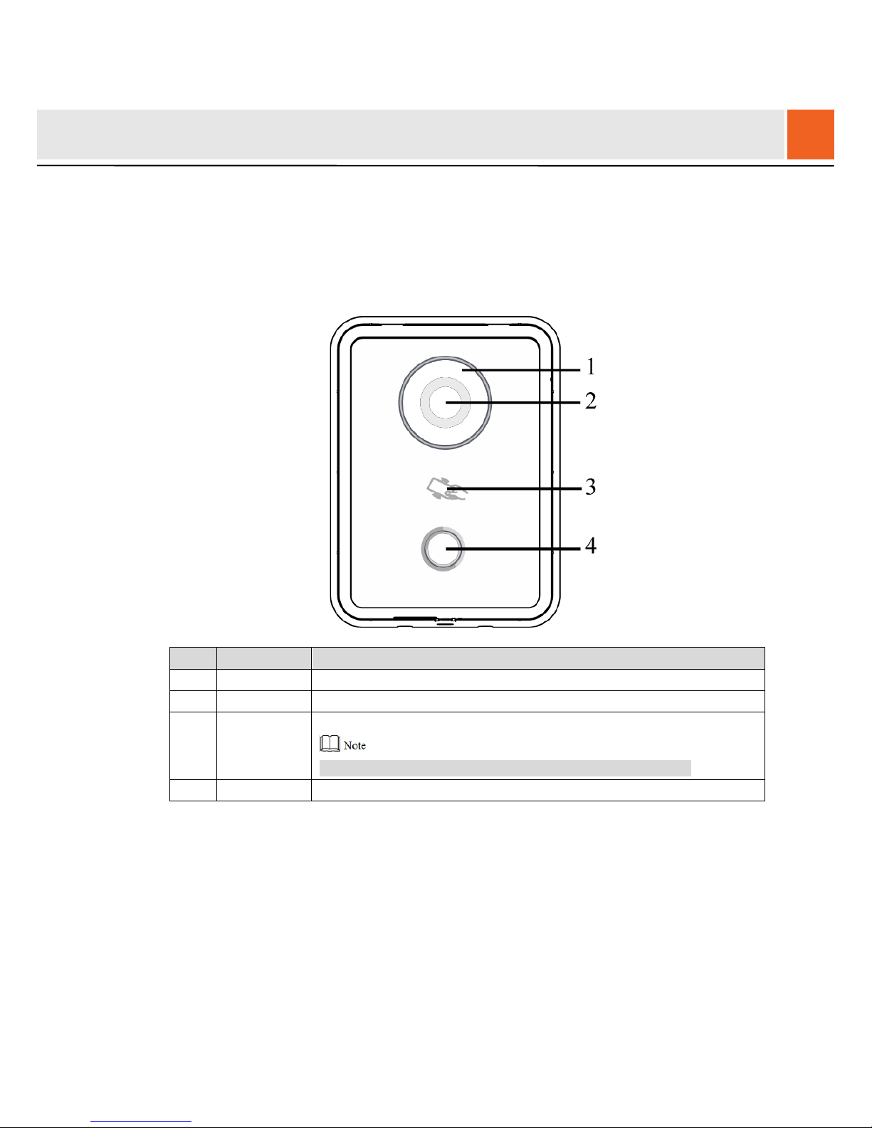
Front Panel
Figure 2-1
No.
Name
Description
1 Fill-in light Provide fill-in light for camera in case of insufficient light.
2
Camera
Monitor the door area.
3
Card
swiping area
Open the door with authoriz ed I C card and swiping card.
Ensure that access extension m odule has been connected.
4
Call key
Call management center or VUH.
Table 2-1
2
Product Structure
Page 14
4
2.1.2
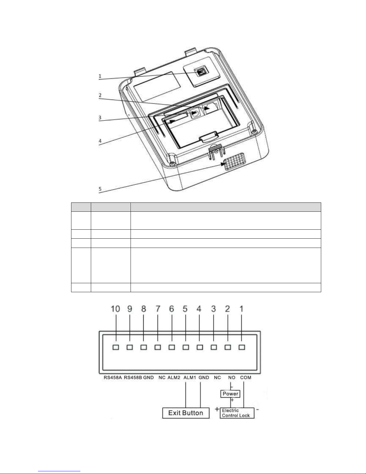
Rear Panel
Figure 2-2
No.
Name
Description
1
Tamper
switch
When VUO is detached from the wall forcibly, give out alar m so und and
report alarm info to manage ment center.
2
Network port
Insert network cable (RJ4 5 plu g) .
3
Power port
Connect 12V DC power supply.
4
10-core port
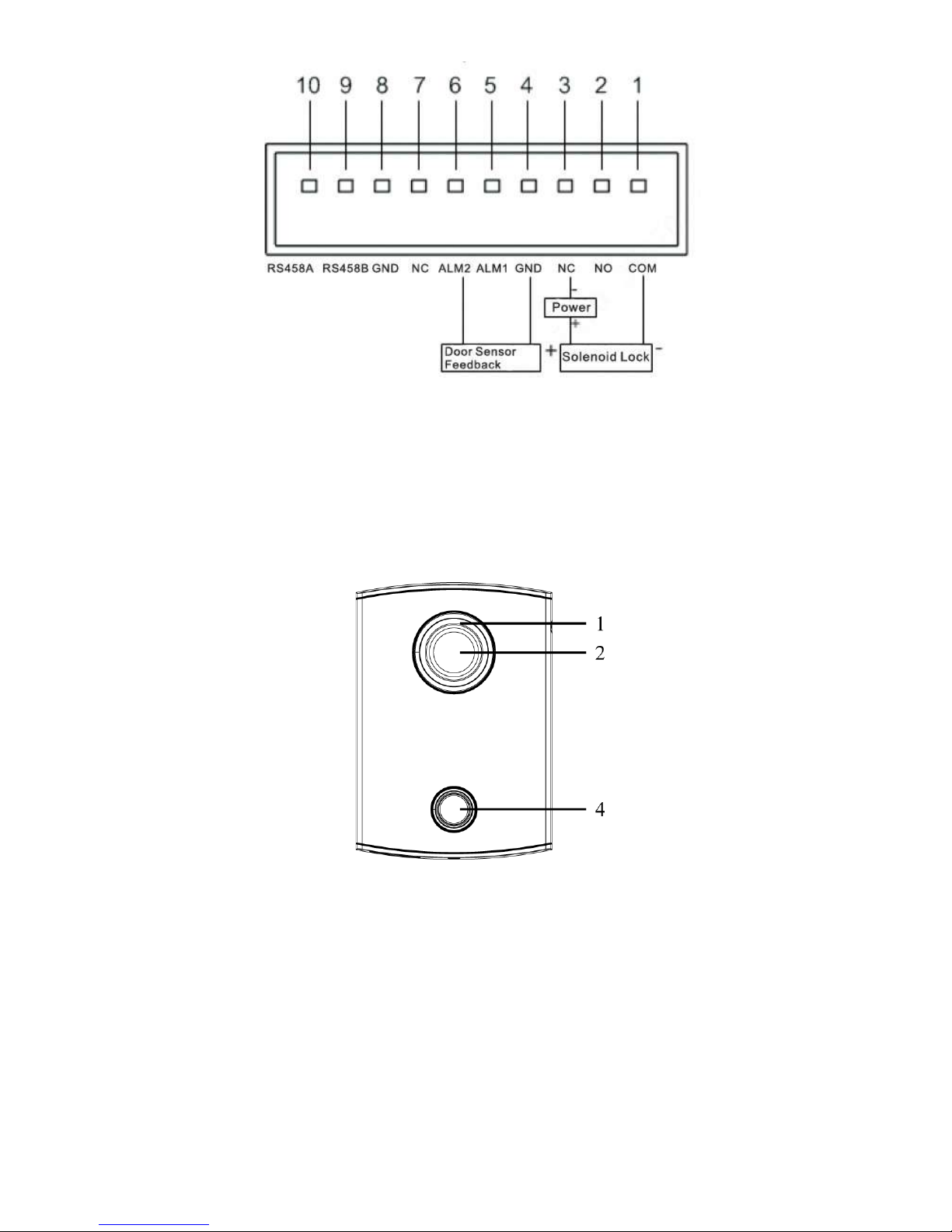
Provide lock port, door sensor feedback port and exit button port
to connect electric control lock, solenoid lock and exit button.
Wiring method is shown in Figure 2-6 and Figure 2-7.
Provide a reserved port to connect access extension module.
5
Speaker
Audio output.
Table 2-2
Figure 2-3
Page 15
5
Figure 2-4
2.2
VUO6000CM/VUO6100C
2.2.1
Front Panel
Figure 2-5
Page 16
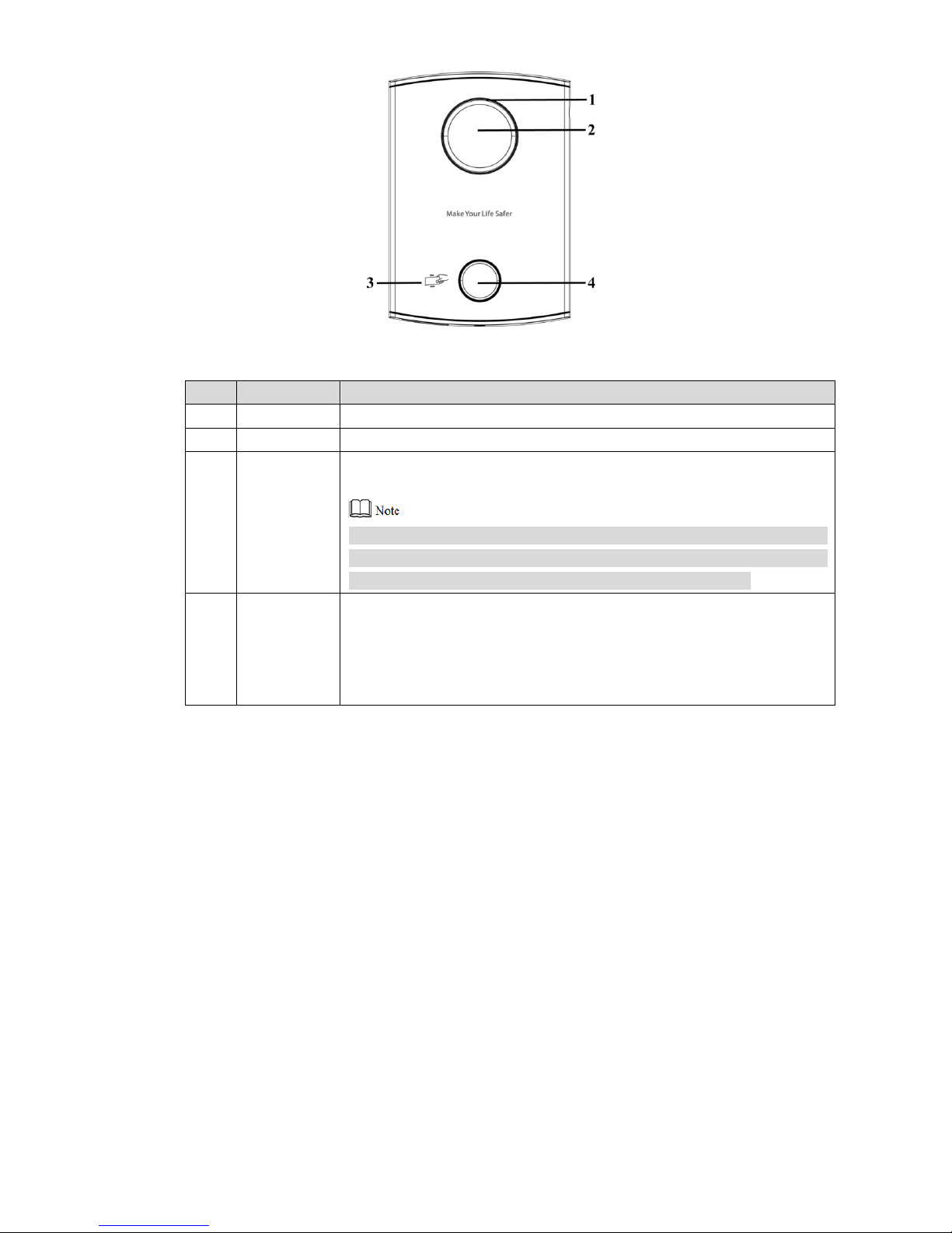
6
Figure 2-6
No.
Name
Description
1
Fill-in light
Provide fill-in light for camera in case of insufficient light.
2
Camera
Monitor the door area.
3
Card
swiping area
Open the door with authorized IC card (card issuing function) and
swiping card.
Only VUO6100C supports to exit with IC card. Silkscreen icon of card
swiping area may have different positions; the actual product shall
prevail. This schematic diagram is only for your refer ence.
4
Call key
Call management center or VUH.
Blue solid light: VUO is in standby status.
Blue flashing light: VUO is calling or
talking.
Yellow: it is unlocked with I C car d or t her e i s a pr oblem in calling.
Table 2-3
Page 17
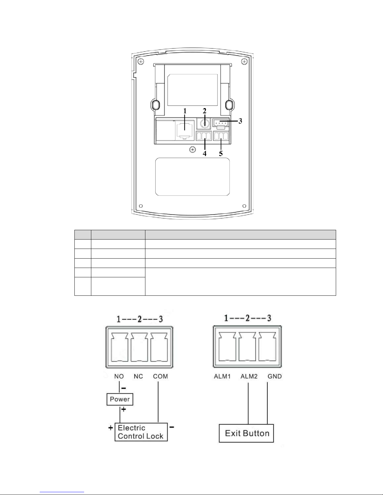
7
2.2.2
Rear Panel
Figure 2-7
No.
Name
Description
1 Network port Insert network cable (RJ4 5 plu g) .
2 Power port Connect 12V DC power supply.
3 Debugging port It is used by engineering personn el during debugging.
4 Green plug port 1 Prov ide lock port, door sensor feedbac k p ort and exit button port to
connect electric control lock, solenoid lock and exit butt on. Wiring
method is shown in Figure 2-8 and Figure 2-9.
5
Green plug port 2
Table 2-4
Figure 2-8
Page 18
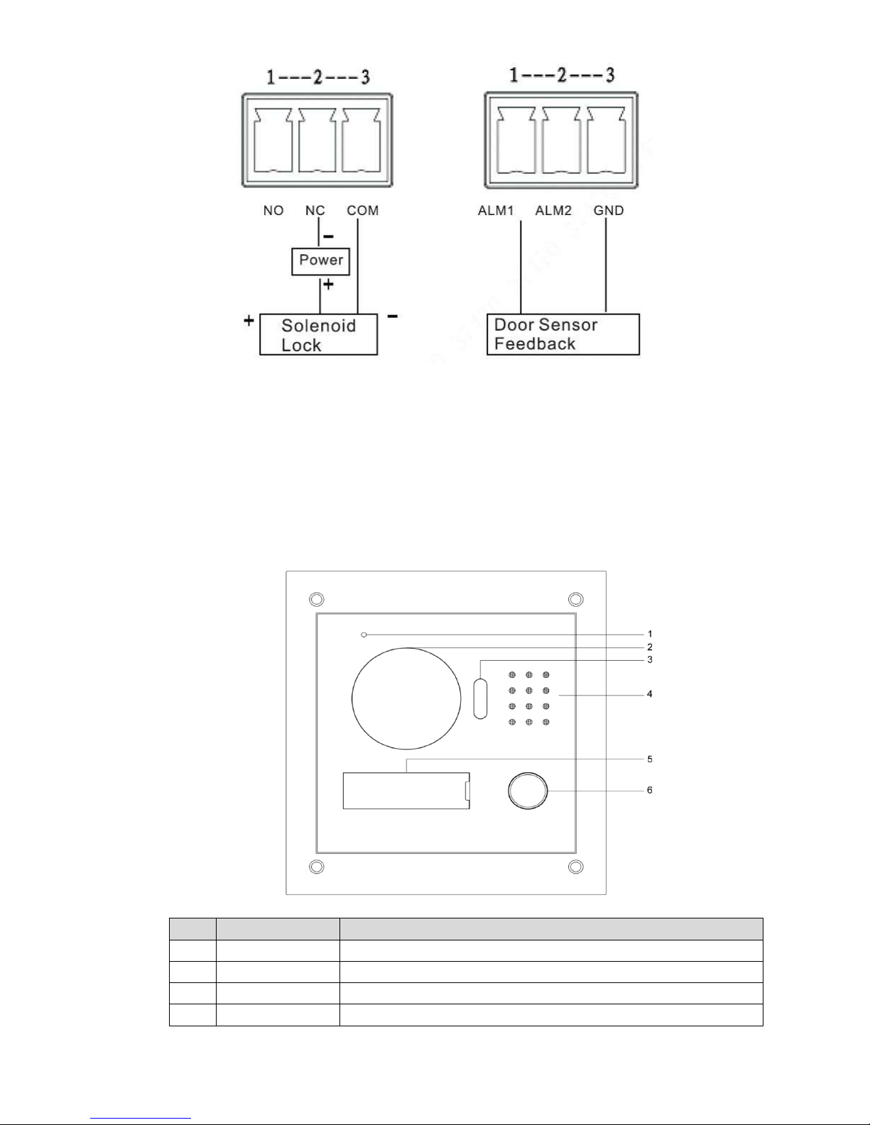
8
Figure 2-9
2.3 VUO2000A/VUO2000A-2
2.3.1
Front Panel
Figure 2-10
No.
Name
Description
1
Microphone
Audio input.
2
Camera
Monitor the door area.
3
Fill-in light
Provide fill-in light for camera in case of insufficient light.
4
Speaker
Audio output.
Page 19
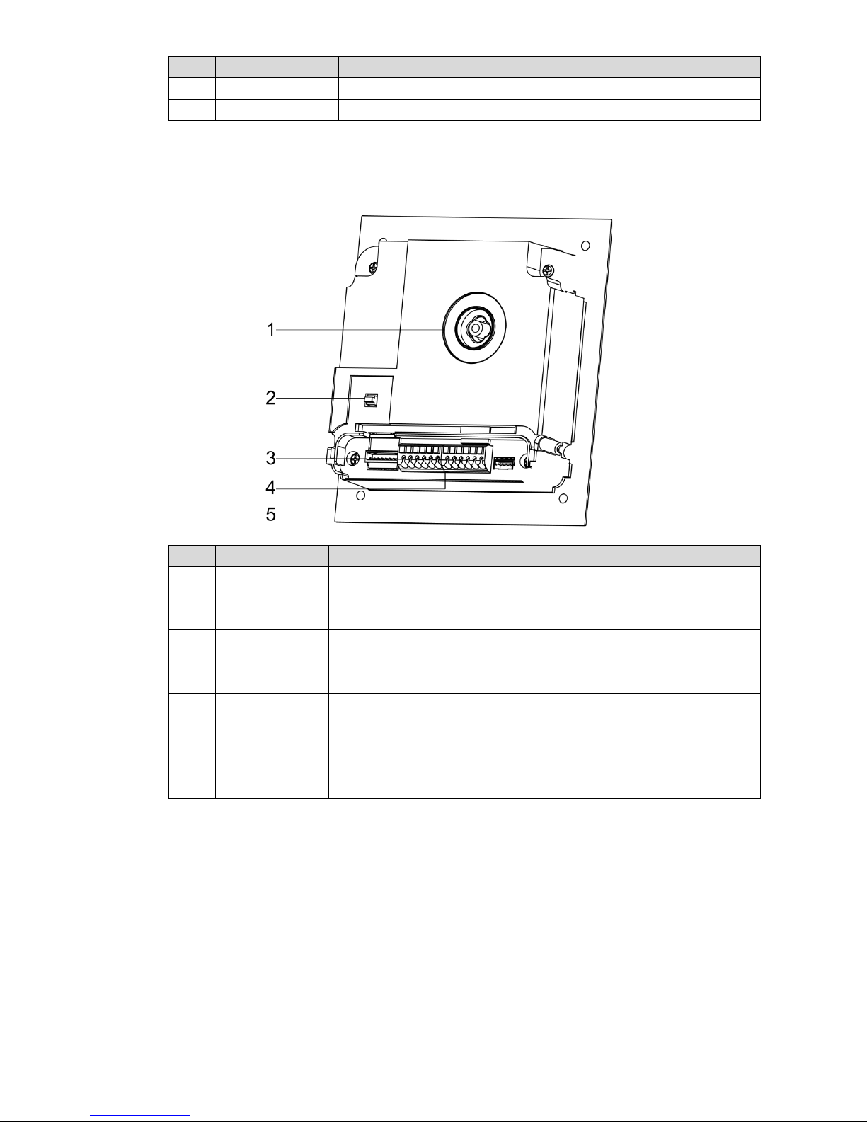
9
No.
Name
Description
5
User directory
Set user info.
6
Call key
Call management center or VUH.
Table 2-5
2.3.2
Rear Panel
Figure 2-11
No.
Name
Description
1
Camera angle
adjusting
column
Adjust camera angle.
2 Tamper switch
When VUO is detached from the wall forcibly, give out alar m so und
and report alarm info to management center.
3 Network port Connect network cable (RJ45 plug) with adapter cable.
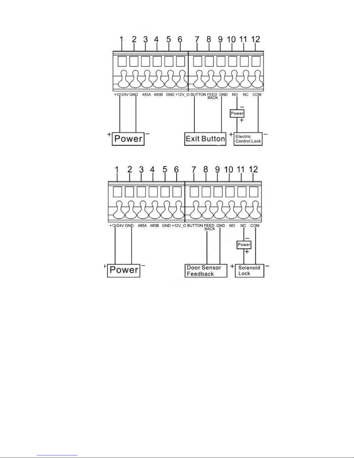
4
User port
Provide power port, lock port, door sensor feedback port and exit
button port to connect power supply, electric control lock, solenoid
lock and exit button. Wiring method is shown in
Figure 2-15 and
Figure 2-13.
5 Debugging port It is used by engineering personn el during debugging.
Table 2-6
Page 20
10
Figure 2-12
Figure 2-13
Page 21
11
Figure 2-14
No.
Name
Description
1
Camera angle
adjusting column
Adjust camera angle.
2 Tamper switch
When VUO is detached from the wall forcibly, give out alar m so und
and report alarm info to management center.
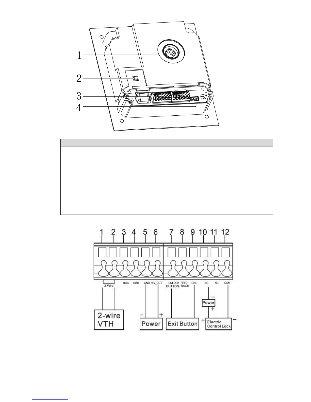
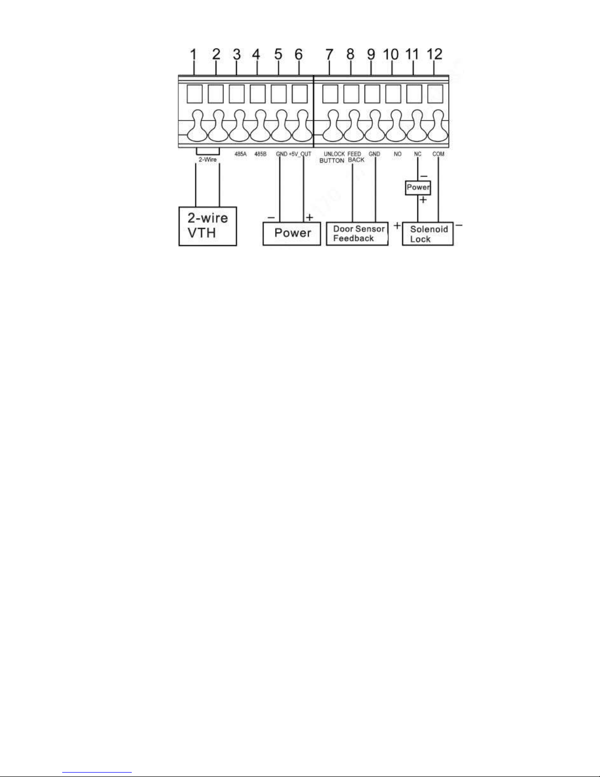
3
User port
Provide power port, 2-wire port, lock port, door sensor feedback
port and exit button port to connect power supply, 2-wire VUH,
electric control lock, solen oid l ock and exit button. Wiring meth od is
shown in Figure 2-15 and Figure 2-16.
4 Debugging port It is used by engineering personn el during debugging.
Table 2-7
Figure 2-15
Page 22
12
Figure 2-16
Page 23

13
3 Networking Diagram
3.1
VUO6210B/VUO6210BW/VUO6000CM/VUO6100C/VU
O 2000A
3.1.1
One-to-one Scene
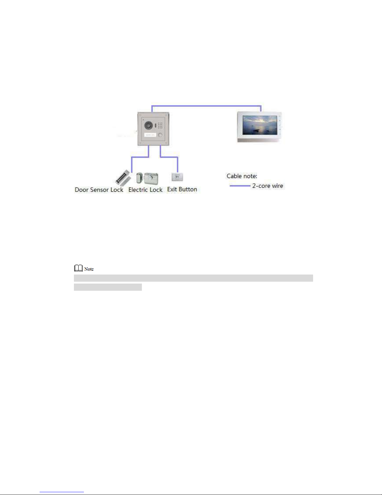
Villa VUO connects with VUH directly. A visitor presses call key on villa VUO to call the
resident (VUH) or Management Center. Take digital villa VUO VUO6110BW for example; its
networking diagram is show n in F igure 3-1.
Figure 3-1
3.1.2
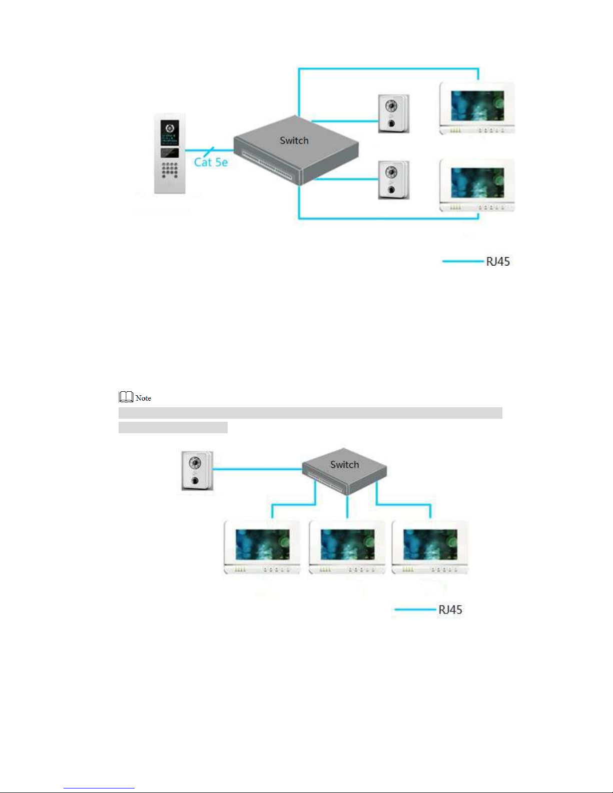
One-to-many Scene
Generally, unit VUO is installed at the gate of apartment building, whereas villa VUO is
installed at the resident’s gat e. The operation process is as follows.
Step 1
Step 2
The visitor calls any resident with unit VUO.
The resident’s VUH rings. After unlo cking, the visitor goes into the apartment building.
Call the resident with villa VUO, and ask the resident t o unloc k the house.
Take digital villa VUO6110BW for example; its networking diagram is shown in Fig ur e 3-2.
Page 24
14
Figure 3-2
3.1.3
Group Call Scene
When the visitor presses call key on villa VUO, multiple VUHs ring at the same t ime; the
resident can pick up, hang up or unlo ck on any VUH.
Take digital villa VUO6110BW for exa mp le; its networking diagram is shown in Figure 3-1.
VUH consists of master VUH and extension VUH. There is 1 ma st er VUH at mo st and 5
extension VUHs at most.
Figure 3-3
Page 25
15
3.2 VUO2000A-2
3.2.1
One-to-one Scene
The visitor presses call key to call the resident (VUH) or Management Ce nter, as shown in
Figure 3-4.
Figure 3-4
3.2.2
Group Call Scene
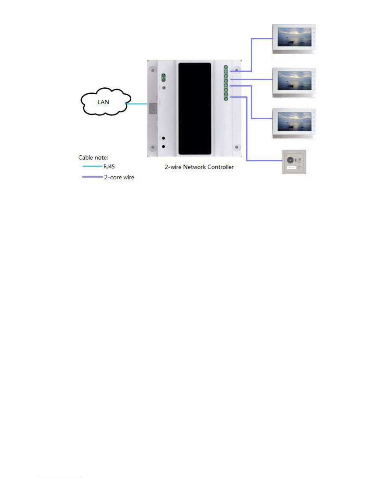
When the visitor presses call key on villa VUO, multiple VUHs ring at the same t ime; the
resident can pick up, hang up or unlo ck on any VUH, as shown in Figure 3-5.
VUH consists of master VUH and extension VUH. There is 1 ma ster VUH at most and 4
extension VUHs at most.
Page 26
16
Figure 3-5
Page 27
17
4.1
Mounting Flow Chart
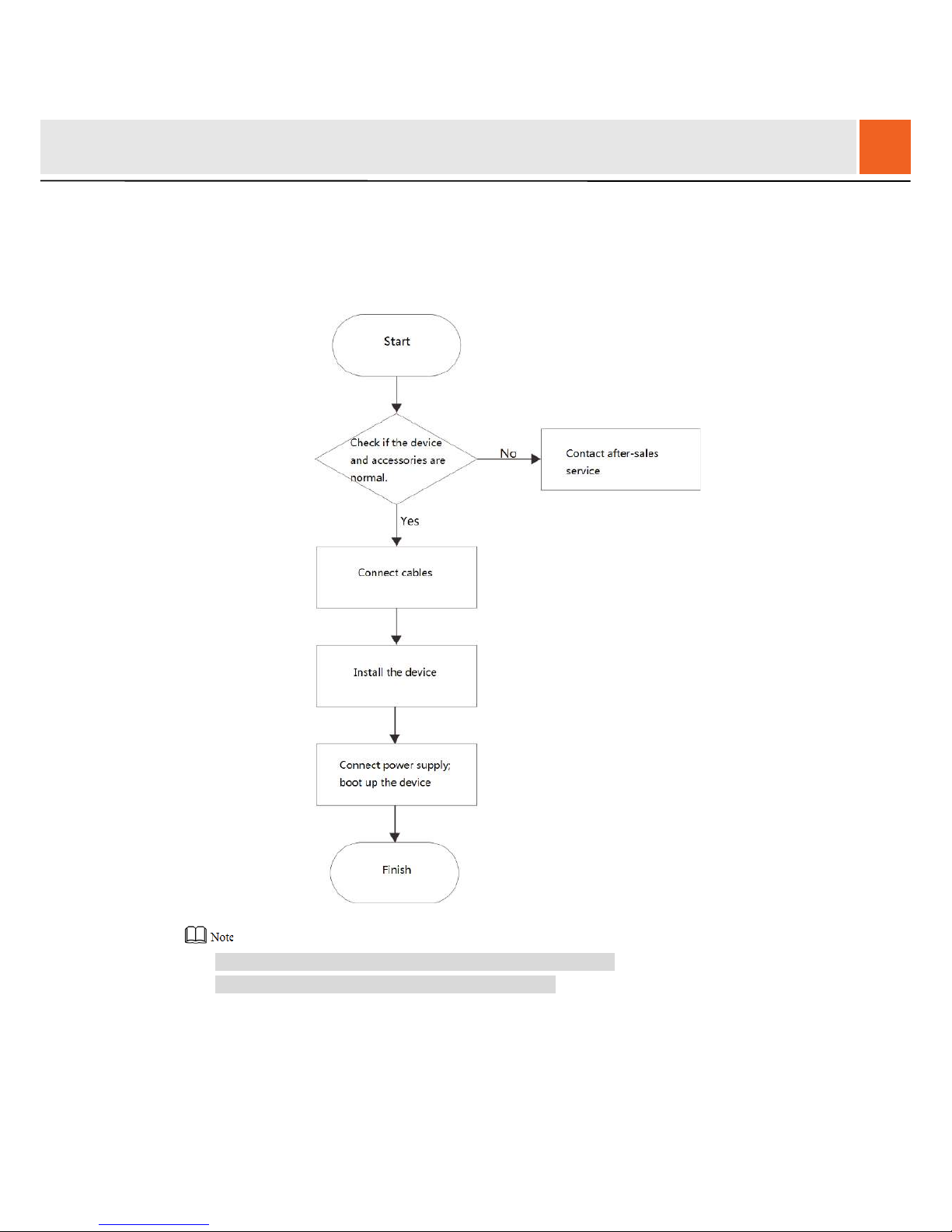
VUO mounting flow char t is shown in Figure 4-1. Please inst all VUO in the following steps.
Figure 4-1
For cable connection, please refer to “2 Product Structure”.
For device mounting, please refer to “4.4 Device ”.
4.2
Open-case Inspection
Please carry out open-case inspection when receiving the device. Please timely contact our
4
Device Mounting
Page 28
18
after-sales service personnel in case of any problems.
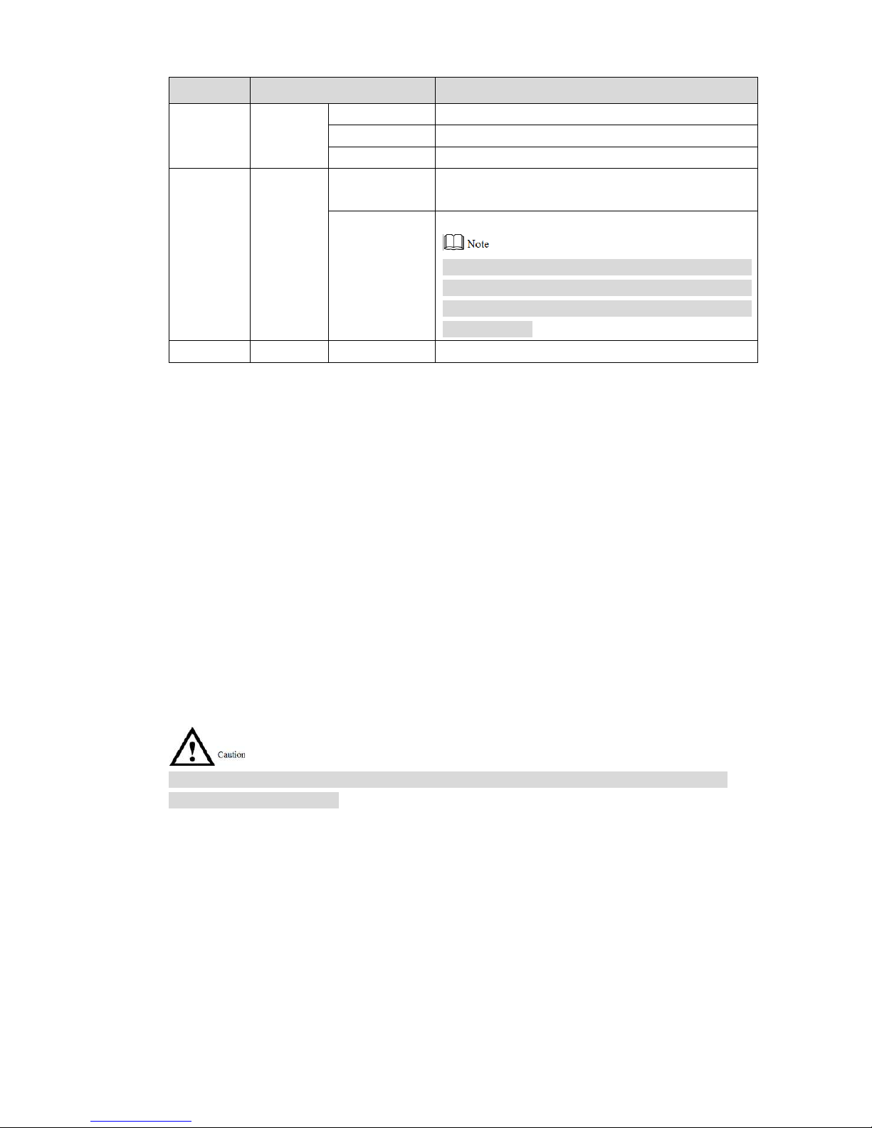
Sequence Item Content
1
Overall
package
Appearance
Inspect whether there are obv ious damages.
Package Inspect whether there are acci dent al impacts.
Fittings Inspect whether fittings ar e c omplete.
2
Model
and label
Device model
Inspect
contract.
whether it is consistent with order
Label
device
on the
Inspect whether it is torn or dam aged.
Don’t tear or discard the label, otherwise warranty
service won’t be provided. When dialing our
after-sales hotline, please provide serial number
of the product.
3 Device Appearance Inspect whether there are obvious damages .
Table 4-1
4.3
Mounting Requirement
Don’t install VUO in bad environment, such as condensation, high temperature, stained,
dusty, chemically corros ive, direct sunshine or unshi elded environment.
Engineering mounting and debugging shal l be done by professional teams. Pl ease don’t
dismantle or repair arbitra r ily in cas e of device failure.
4.4
Device Mounting
4.4.1
VUO6210B and VUO6210BW
Before installing the brac ket or flus h mount box, cables in the wall shall be led through the
bracket or flush mount box.
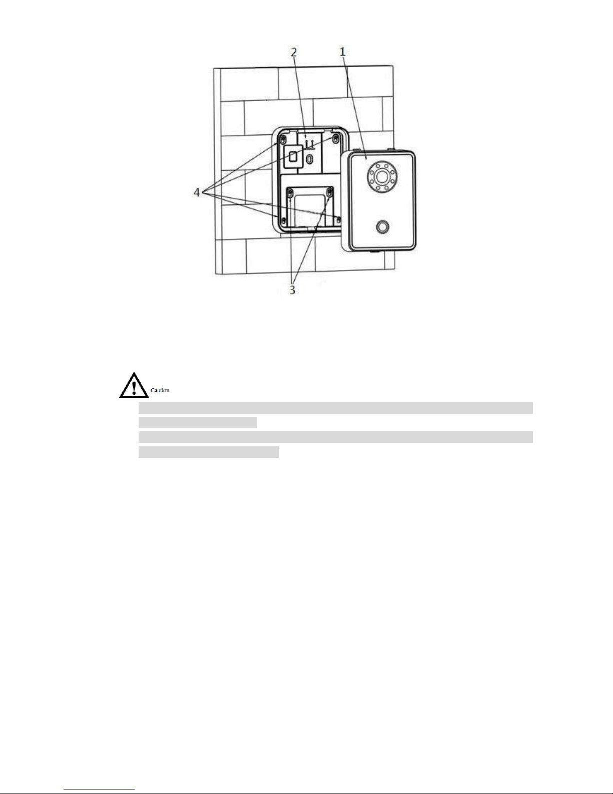
Mounting method of VUO6210B and VUO6210BW is the same. Take “VUO6210B” for example.
Step 1
Step 2
Step 3
Step 4
Fix the mounting bracket onto the wall.
1. Fix the bracket onto 86 box with M4 screws. Screw holes are located in Points 3 a
s
shown in the figure.
2. To strength en pr oduct firmness, tighten it w it h S T3. 0 screws in Points 4 as show
n
i
n the figure.
Connect cables. Please refer to “2.1.2 Rear Panel” for detai ls.
Put the bare device onto the mounting bracket; fit the upper edge first and then push
the lower edge gently.
Fix the whole device onto the bracket with M3 screws.
Page 29
19
Figure 4-2
4.4.2
VUO6000CM and VUO6100C
Before insta ll ing the bracket or flush mount box, cables in the wall shall be led through the
bracket or flush mount box.
Try not to install VUO6100C onto an iron door directly. Otherwise, signals may be shiel ded
and card induction may be poor.
Step 1
Step 2
Step 3
Step 4
Step 5
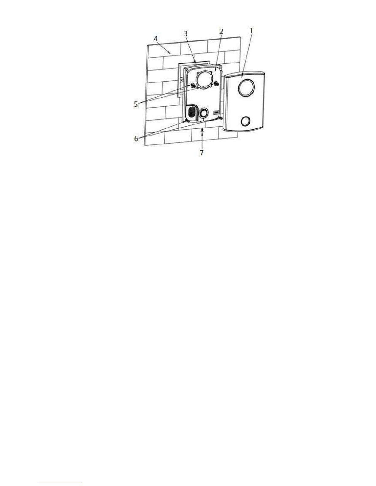
Dismantle M3 screws at the bot tom of VUO and take off the decorative cap.
Connect cables. Please refer to “2.2.2 Rear Panel” for detai ls.
Fix the bare device onto 86 box with M 4 sc rews. Screw holes are locat ed in Points 3 as
shown in the figure.
To strengthen product fir mn ess, after 86 box is in place, tighten it w it h S T3. 0 screws in
Points 6 as shown in the figure.
Install the decorative cap onto the bare device, and fix it with M 3 scr ew s .
Page 30
20
Figure 4-3
4.4.3 VUO2000A/VUO2000A-2
VUO2000A and VUO2000A-2 devices support the same mou nt ing method and process. Ta ke
“VUO2000A” for exampl e.
4.4.3.1 Surface Mounting
Step 1
Step 2
Step 3
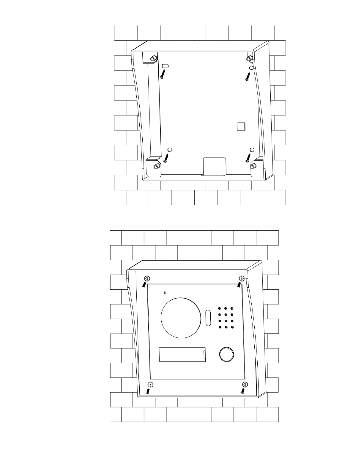
Drill holes according to hole pos itions of sheet metal bracket, and put expansion pipe in
place.
Connect cables. Please refer to “2.3.2 Rear Panel” for detai ls.
Fix sheet metal bracket onto t he w all with ST3×18 screw s.
Page 31
21
Step 4
Figure 4-4
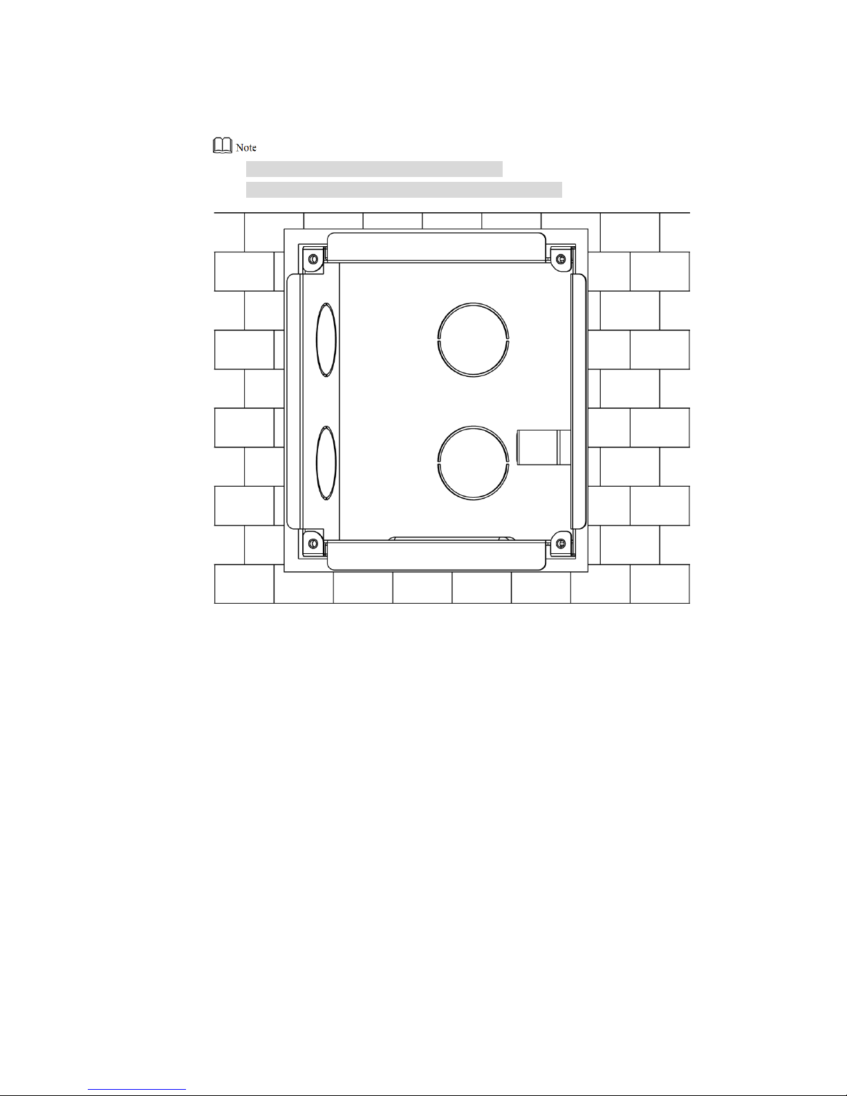
Fix the bare device onto sheet m et al bracket with M3×6 screws.
Figure 4-5
Page 32
22
4.4.3.2 Flush Mounting
Step 1
Step 2
Step 3
Dig a hole in the wall, embed flush mou nt ing box into the wall, and ensure tha t box
edge clings to the wall.
Hole dimensi on is 117mm×128mm×80mm.
During flush mo unt ing, lead cables out from the wall.
Figure 4-6
Connect cables. Please refer to “2.3.2 Rear Panel” for detai ls.
Fix the bare device onto the box with M3×8 screws.
Page 33
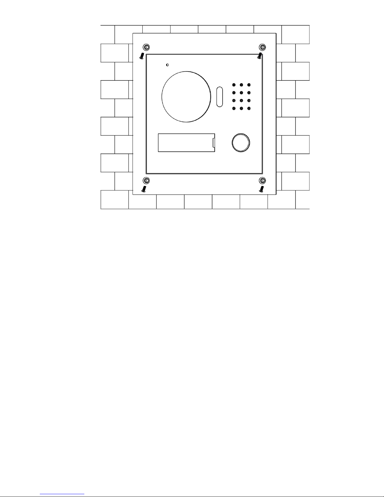
23
Figure 4-7
Page 34

24
5 Device Debugging
Carry out debugging to ensure that the device can realize basic network access, call and
monitoring functions after installation. Before debugging, please check whether the following
work has been completed.
Debugging per sonnel shall get familiar with re levant documents in advance, and get to
k
now device mounting, wir ing and use.
Check whether t here is short circuit or open circuit. Power on the device only after t he
ci
rcuit is confirmed to be normal.
IP and no. (or room no.) of every VUO and VUH have been planned.
5.1
Debugging Settings
5.1.1
VUO Settings
5.1.1.1 Initialization
For the first time, please initia lize login password.
Please ensure that default IP addresses of PC and VUO are in the same network segment.
Default IP address of VUO is 192.168.1.110.
Step 1
Step 2
Connect VUO power and boot up.
Enter default IP address of VUO at the address bar of PC browser.
The system displays “Setting” interface, as shown in Fig ur e 5-1.
Page 35
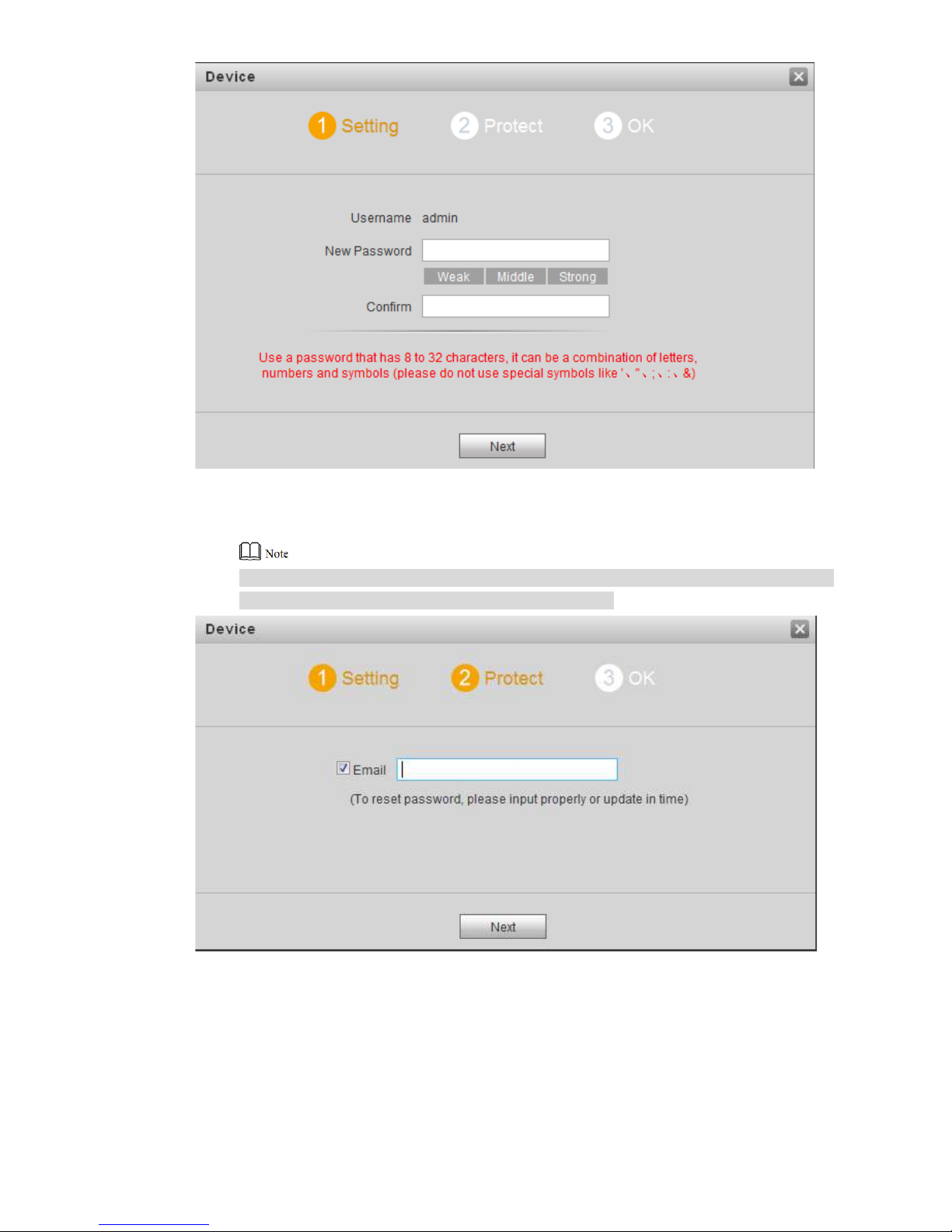
25
Step 3
Step 4
Step 5
Figure 5-1
Enter “New Password” and “ Confirm”, and click “Next”.
The system displays “Protect” interface, as shown in Figure 5-2.
This password is used to login WEB interface. It shall be at least 8 char acters, and shall
include at least two types of num ber , letter and symbol.
Figure 5-2
Select “Email” and enter your Email address.
This Email address is used t o r eset t he pas sw or d, so it is recommended that it s houl d
be set.
Click “Next” .
The system displays “OK” inter face, as shown in Figure 5-3, and sh ows “Device
succeeded!”
Page 36
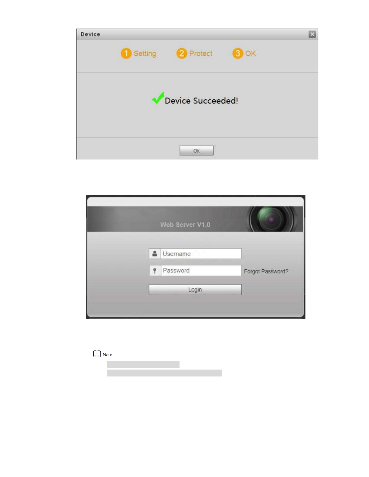
26
Step 6 Click “OK”.
Figure 5-3
The system displays WEB login interface, as shown in Figur e 5-4.
Step 7
Figure 5-4
Enter username and password, and click “Login”.
Log in the WEB interface of the device.
Default userna me is admin.
Password is the one set during initialization.
5.1.1.2 Network Config
Modify IP address of VUO to be planned IP address.
Step 1 Select “System Config > Network Config > TCP/IP”.
The system displays “TCP /IP” interface, as shown in Figure 5-5.
Page 37
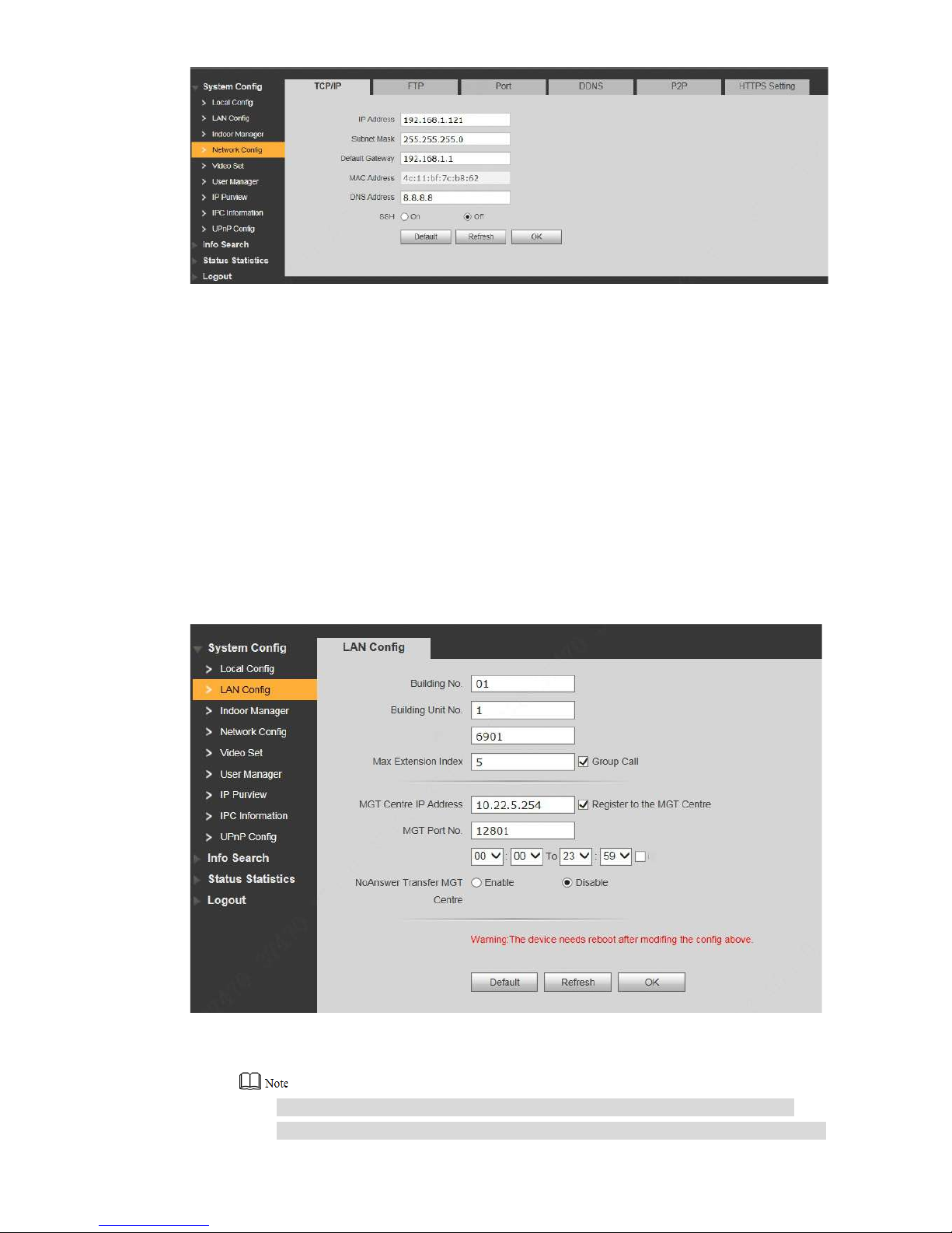
27
Step 2
Figure 5-5
Enter the planned “IP Address”, “Subnet Mask” and “Default Gateway”, and click “OK”.
After modification is completed, VUO reboots automatically, while the following two
cases occur at WEB interface.
If PC is in the planned network segment, WEB interface jumps to new IP log in
i
nterface automatically.
If PC is not in the planned network segment, t he webpage cannot be displaye d.
Please add PC into the planned network segment and login WEB interface again.
5.1.1.3 LAN Config
Set building no., unit no. and VUO no..
Step 1
Step 2
Select “System Config > LAN Config”.
The system displays “LAN Config” interface, as shown in F igure 5-6.
Figure 5-6
Enter VUO “Building No.”, “Build ing Un it No.” and “VUO No.”.
To call management c entre, please select “Register to the MGT Centre”; set
“MGT Centre IP Address” and “ M G T Port No.”. Set “Call VUS Time” and t ick “Call
Page 38
28
Step 3
VUS or Not”.
To provide group cal l, ple ase select “Group Call” and set “Max Extension Index”
which can be 5 at most.
Click “OK”.
5.1.1.4 Add VUH
Add VUH info. After VUH and VUO debugging is completed, VUH will be regist er ed t o VUO
automatically, in order to real ize binding.
Add master VUH only.
After “Network Terminal” interface of extens io n VUH adds main VUO and enables it, VUO
interface will obtain extension VUH info automatically.
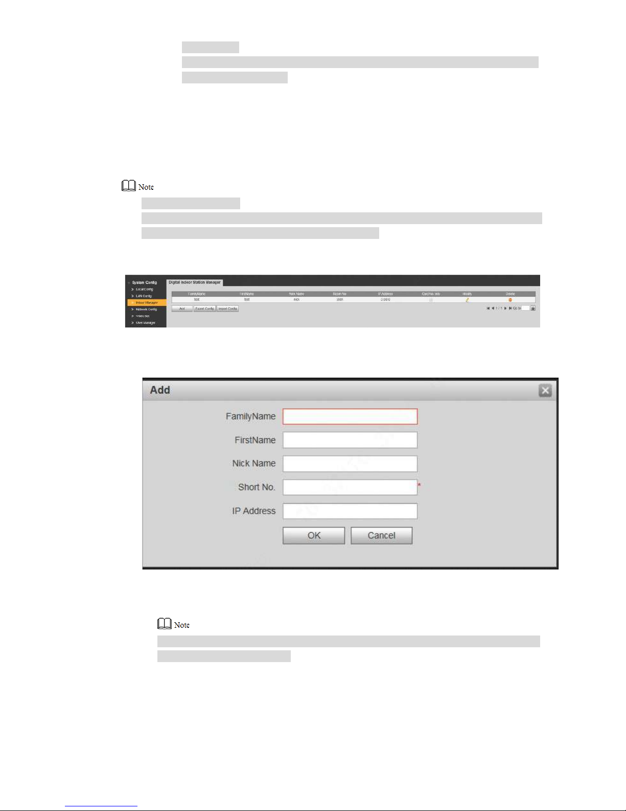
Step 1 Select “System Config > Di gital Indoor Station Manager”.
The system displays “Digital Indoor Station Manager ” inter fa c e, as shown in Figure 5-7.
Step 2 Click “Add”.
Figure 5-7
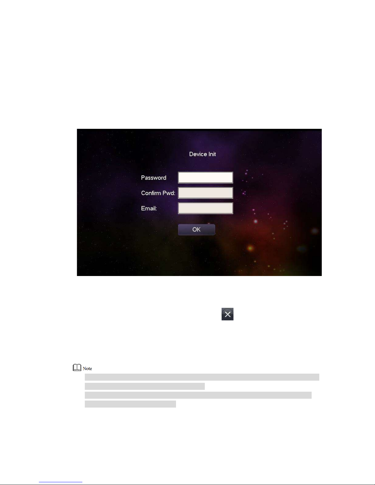
The system displays “Add” int erface, as shown in Figure 5-8.
Step 3
Step 4
Figure 5-8
Enter VUH “Family Name”, “First Name”, “Nick Name”, “VUH Short No.” (VUH room no.)
and “IP Address”.
It is OK if IP address is not filled in. A fter VUH is reg istered to VUO successfully, VUO
will obtain IP address of VUH.
Click “OK”.
Page 39
29
5.1.2
VUH Config (Version 3.1)
5.1.2.1 Initialization
Set the password and bind your Em ai l.
Password: it is used t o enter project setting interface.
Email: it is used to r et r ieve your password when you forget it.
Step 1
Step 2
Step 3
Power on the device.
The system displays “Welcome” and enters “Device Initial ization” interface, as shown in
Figure 5-9.
Figure 5-9
Enter “Password”, “Confirm Pwd” and “Email”. Click [ OK].
Click “OK”.
The system displays “Info I nit ” inter f ace. Press to turn it off.
5.1.2.2 Network Setting
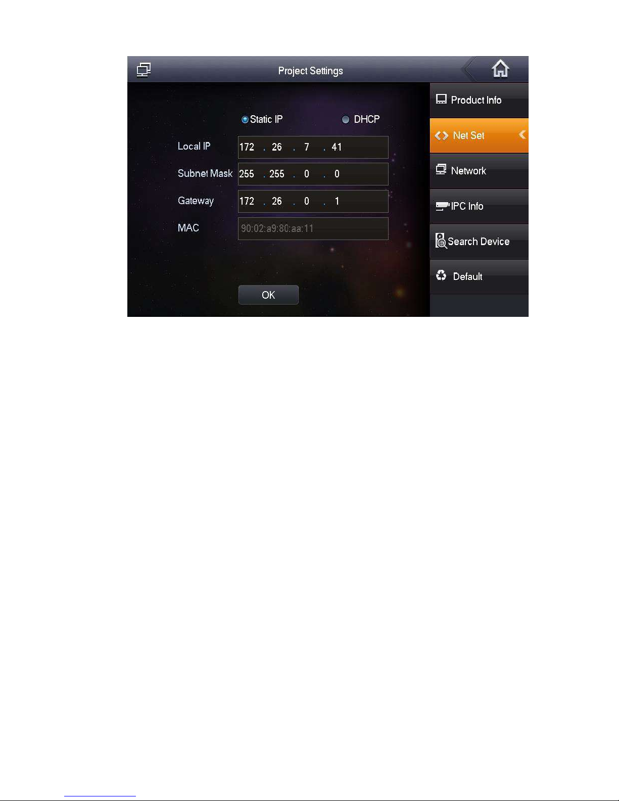
Set VUH network information; Support st at ic I P and DHCP.
IP addresses o f VUH and VUO shall be in the same netw ork segment. Otherwise, VUH
will fail to obt ain VUO info after configuration.
To obtain IP with DHCP, please ensure the c onnected router has DHCP function and
DHCP function has been enabled.
Step 1
Step 2
Step 3
Select “System Config >Project Settings”.
The system pops up “Passw or d” pr ompt box.
Enter the password set during init i al ization, and click [OK].
Click [Net Set].
Page 40
30
The system displays “Net Set” interface, as shown in Figure 5-10.
Step 4
Figure 5-10
Set according to actual net w or k acces s mode.
Static IP
1. Select “Static IP”.
2. Enter “Local IP”, “Subnet Mask” and “Gateway”.
Step 5
DHCP
Select “DHCP” to obtain IP address automatically.
Click [OK] to save the settings.
5.1.2.3 Product Info
Set VUH “Room No.”, type and “Master IP”.
Step 1
Step 2
Step 3
Select “System Config >Project Settings”.
The system pops up “Passw or d” pr ompt box.
Enter the password set during init i al ization, and click [OK].
Press [Product Info].
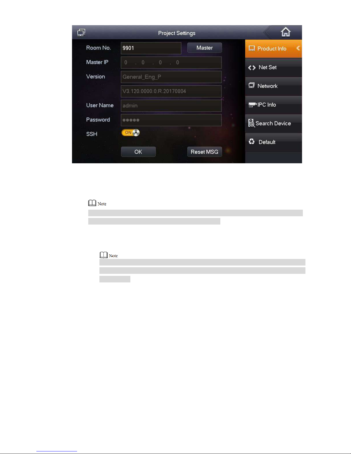
The system displays “Pro duct Info” interface, as shown in Fig ur e 5-11.
Page 41
31
Step 4 Set VUH info.
Figure 5-11
Be used as a mast er VUH.
E
nter “Room No.” (such as 9901).
“Room no.” shall be the same with “ VUH Shor t No. ”, which is set when adding VUH at
WEB interface. Otherwise, it will fail to connect VUO.
Be used as an extension VUH.
1. Press [Master] and switch to “Extension”.
2. Enter “Room No.” (such as 9901-1) and “Mast er I P” (IP address of master VUH).
Step 5
“Username” and “Password” are the username and password of master VUH.
Default username is admin, and the password is the one set during device
initialization.
Click [OK] to save the settings.
5.1.2.4 Set Network
Add VUO and fence station info; at VUH interface, bind VUH with VUO and fence station.
Step 1
Step 2
Step 3
Select “System Config >Project Settings”.
The system pops up “Passw or d” pr ompt box.
Enter the password set during init i al ization, and click [OK].
Press [Network].
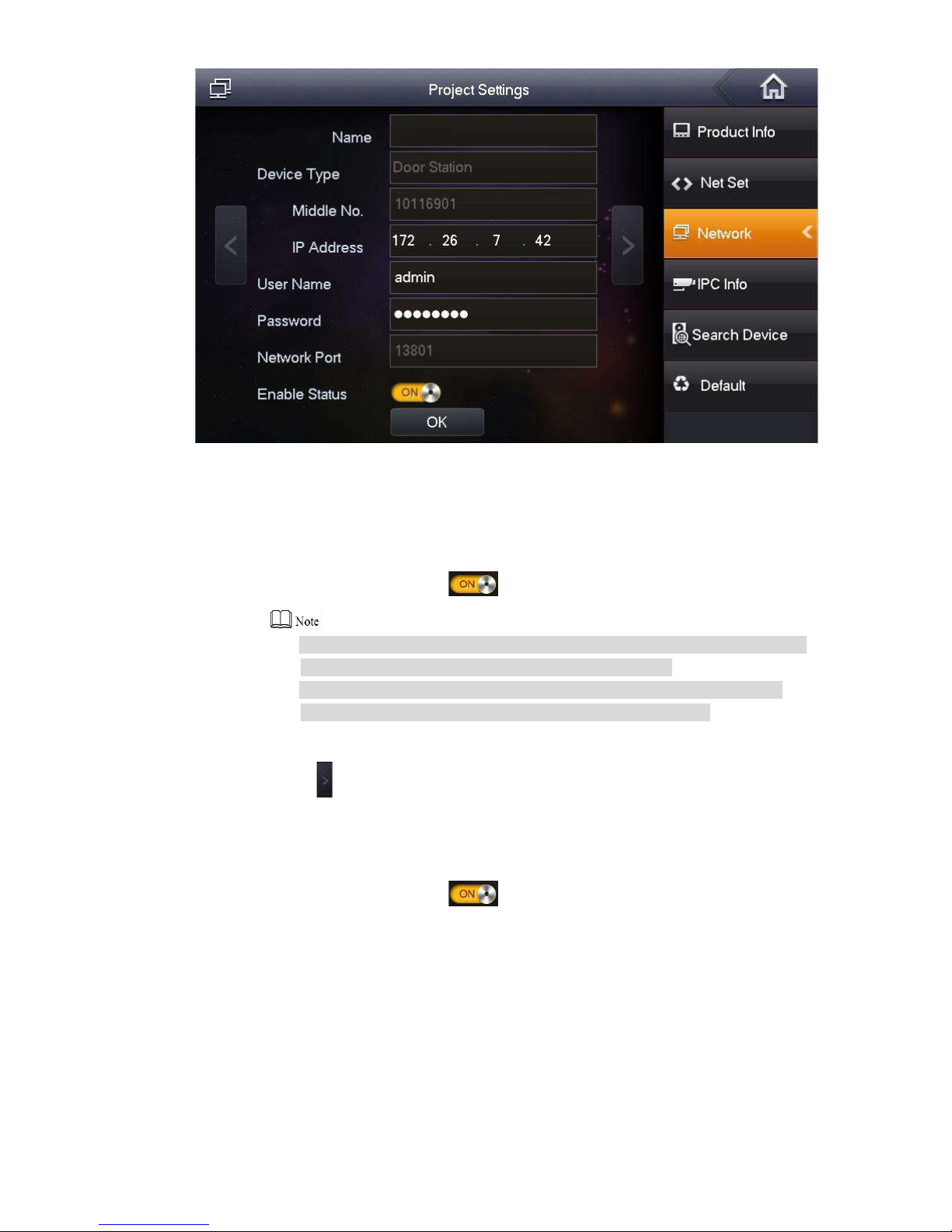
The system displays “Net work” interface, as shown in Figure 5-12.
Page 42
32
Step 4 Add VUO or fence station.
Add main VUO.
Figure 5-12
1. In Figure 5-12, enter main VUO name, IP address, “Username” and “Password”.
2. Switch “Enable Status” to .
“Username” and “Password” shall be consistent with WEB login username
and password of VUO. Otherwise, it will fail to connect.
“Enable status” of main VUO is “ON” by default. After set t ing VUO info,
please turn it off and then reboot, in order to put it into effect.
Add fence station.
1. Press to switch to sub VUO setting interface.
2. Select device type to be “fence station”; enter sub VUO name (fence station name),
VUO middle no. (fence st at ion middle no.), “Username” and “Password”.
3. Switch “Enable Status” to .
Step 5 Click [OK] to save the sett ings.
5.1.3
VUH Settings (Version 4.0)
5.1.3.1 Initialization
Set the password and bind your Em ai l.
Password: it is us ed to enter project setting interface.
Page 43
33
Email: it is used to r et r ieve your password when you forget it.
Step 1
Step 2
Power on the device.
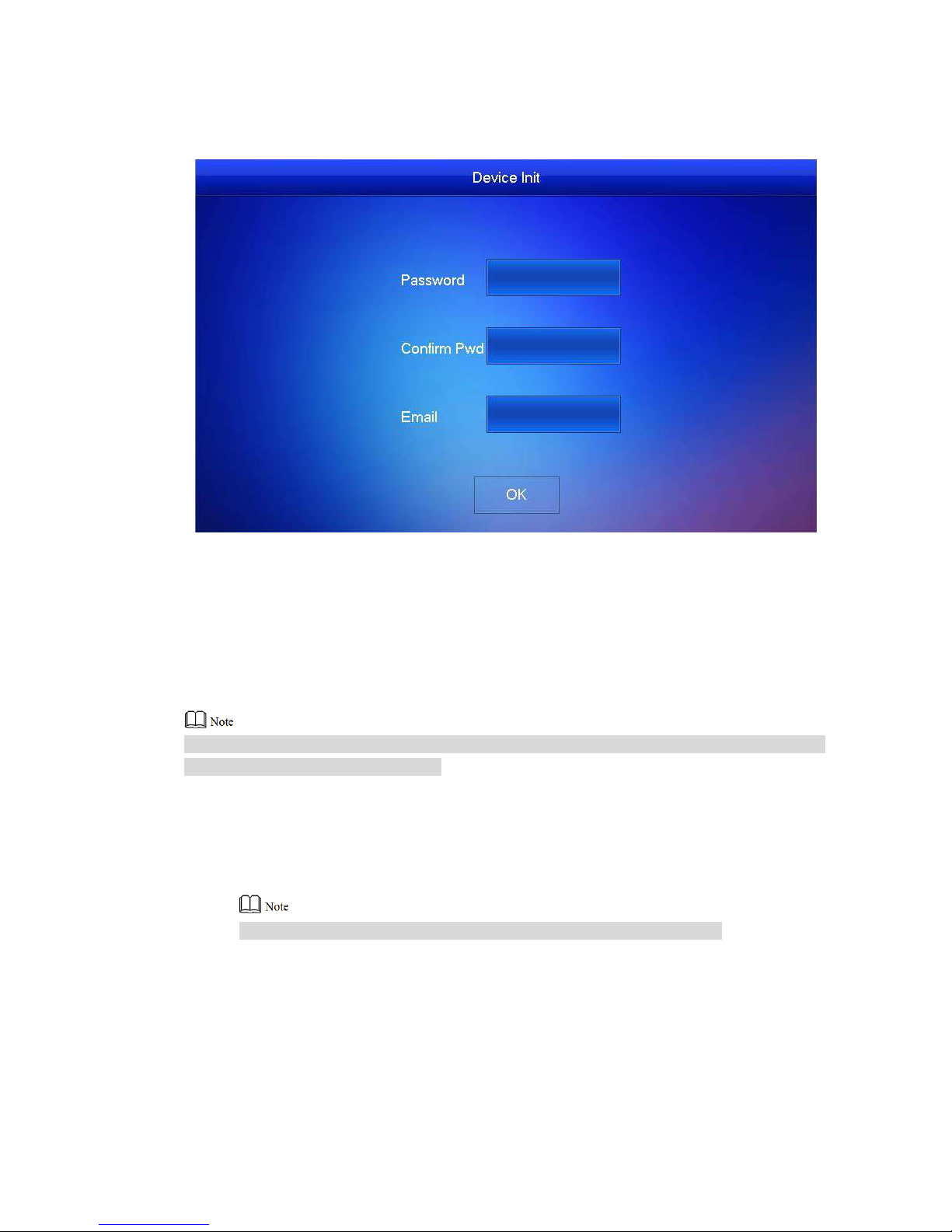
The system displays “Welcome” and enters “Device Initial ization” interface, as shown in
Figure 5-13.
Figure 5-13
Enter “Password”, “Confirm Pwd” and “Email”. Click [ OK].
The system displays main inter face.
5.1.3.2 Set Network
According to available net w or k c onnection modes, configure VUH network information.
IP addresses of VUH and VUO shall be in the same network segment. Otherwise, VUH will fail
to obtain VUO info after c onf ig ur at ion.
Step 1
Step 2
Step 3
Press [Setting] for more th an 6 s econds.
The system pops up “Passw or d” pr ompt box.
Enter the password set during init i al ization, and click [OK].
Click [Netw o rk].
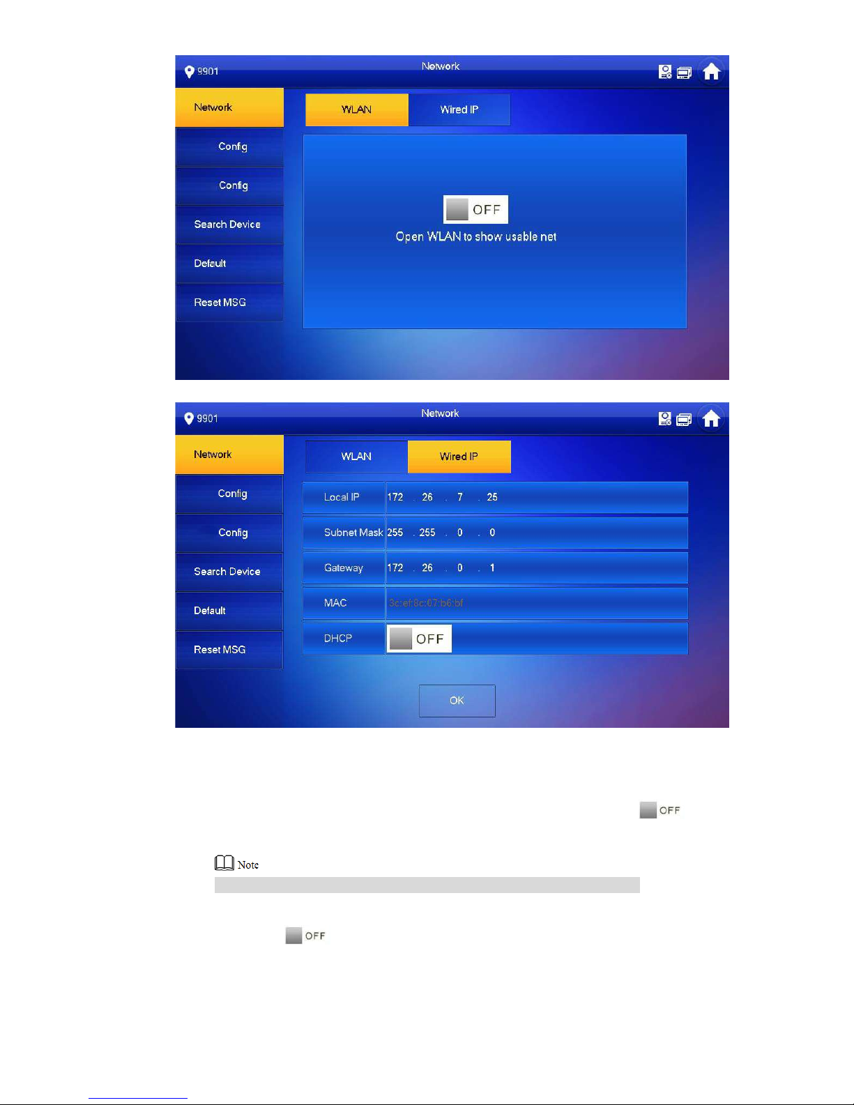
The system displays “Net work” interface, as shown in Figure 5-14 or Figure 5-15.
Only devices with the wireless fun ct ion can access to wireless network.
Page 44
34
Figure 5-14
Step 4
Figure 5-15
Set according to actual net w or k acces s mode.
Wired IP
Enter “Local IP”, “Subnet M ask” and “Gateway”, press [OK] . O r pr ess to enable
DHCP function and obtain I P info automatically.
If the device has wireless funct ion, please click “Wired IP” tab t o set it.
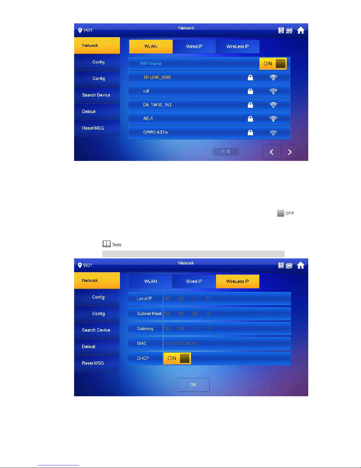
WLAN
1. Press to enable WIFI function.
The system displays avail abl e WIFI list, as shown in Figure 5-16.
Page 45
35
Figure 5-16
2. Connect WIFI.
The system has 2 access way s as follow s.
◇ At “WLAN” interface, select WIFI, click “Wireless IP” tab to enter “ Local IP” ,
“Subnet Mask” and “Gate way”, and press [OK].
◇ At “WLAN” interface, select WIFI, click “Wireless IP” tab, press to
enable DHCP function an d obt ain IP info automatically, as shown in Figure
5-17
.
To obtain IP info with DHCP funct ion, use a router with DHCP function.
Figure 5-17
Page 46
36
5.1.3.3 VUH Config
Set VUH “Room No.”, type and “Master IP”.
Step 1
Step 2
Step 3
Press [Setting] for more th an 6 s econds.
The system pops up “Passw or d” pr ompt box.
Enter the password set during init i al ization, and click [OK].
Click [VUH Config].
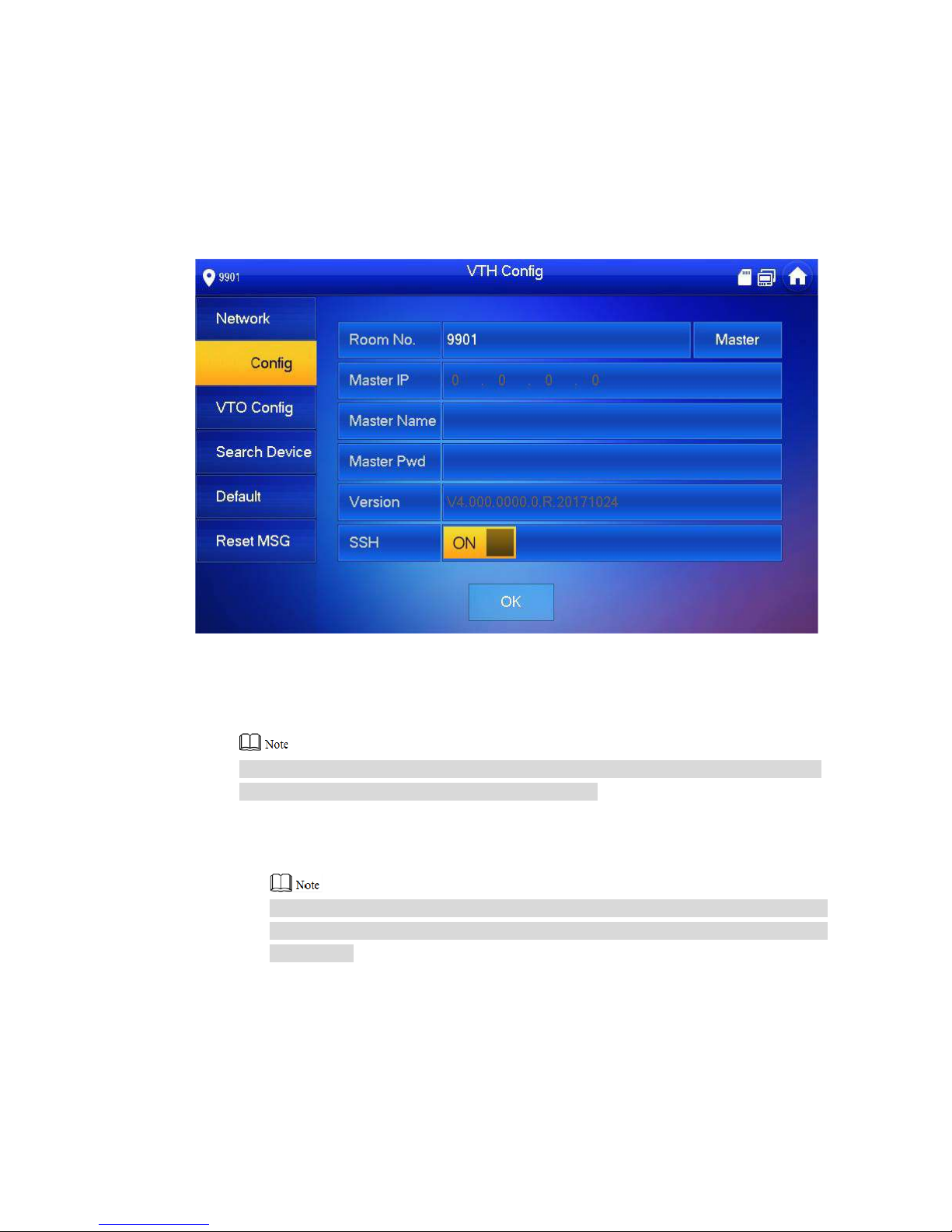
The system displays “VUH Config” interface, as shown in Figure 5-18.
Step 4 Set VUH info.
Figure 5-18
Be used as a mast er VUH.
E
nter “Room No.” (such as 9901).
“Room no.” shall be the same with “ VUH Shor t No. ”, which is set when adding VUH at
WEB interface. Otherwise, it will fail to connect VUO.
Be used as an extension VUH.
1. Press [Master] and switch to “Extension”.
2. Enter “Room No.” (such as 9901-1) and “Mast er I P” (IP address of master VUH).
Step 5
“Master Name” and “Master Pwd” are the username and password of master VUH.
Default username is admin, and the password is the one set during device
initialization.
Press [OK] to save settings.
5.1.3.4 VUO Config
Add VUO and fence station info; at VUH interface, bind VUH with VUO and fence station.
Step 1 Press [Setting] for more th an 6 s econds.
The system pops up “Passw or d” pr ompt box.
Page 47
37
Step 2
Step 3
Enter the password set during init i al ization, and click [OK].
Click [VUO Config].
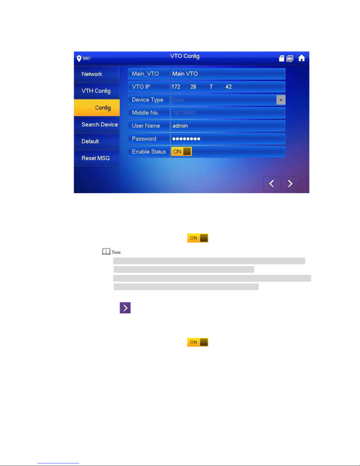
The system displays “VUO Config” int erface, as shown in Figure 5-19.
Step 4 Add VUO or fence station.
Add main VUO.
Figure 5-19
1. In Figure 5-19, enter main VUO name, VUO IP, “Username” and “Password”.
2. Switch the “Enable Status” to be .
“Username” and “Password” shall be consistent with WEB login username
and password of VUO. Otherwise, it will fail to connect.
“Enable Status” of main VUO is “ON” by default. After sett ing VUO info, it will
take effect after turning it of f and then turning it on again.
Add fence station.
1. Press to switch to sub VUO setting interface.
2. Select device type to be “Fence Station”, enter Sub VUO name (fenc e station
na
me), middle no. (fence station no.), “Username” and “Password”.
3. Switch the “Enable Status” to be .
Page 48
38
5.2
Debugging Verification
5.2.1
Verification with Version 3.1 VUH
5.2.1.1 VUO Calls VUH
Press call key at VUO, to call VUH. VUH pops up monitoring image and operating keys, as
shown in Figure 5-20. It represents succe ssful debugging.
Figure 5-20
5.2.1.2 VUH Monitors VUO
VUH is able to monitor VUO, fence station or IP C. Take “VUO” for example.
Select “Video Talk > Moni t or > Door St at io n” , as shown in Figure 5-21. Select the VUO to
enter monitoring image, a s s how n i n Fi gur e 5-22.
Page 49
39
Figure 5-21
Figure 5-22
5.2.2
Verification with Version 4.0 VUH
5.2.2.1 VUO Calls VUH
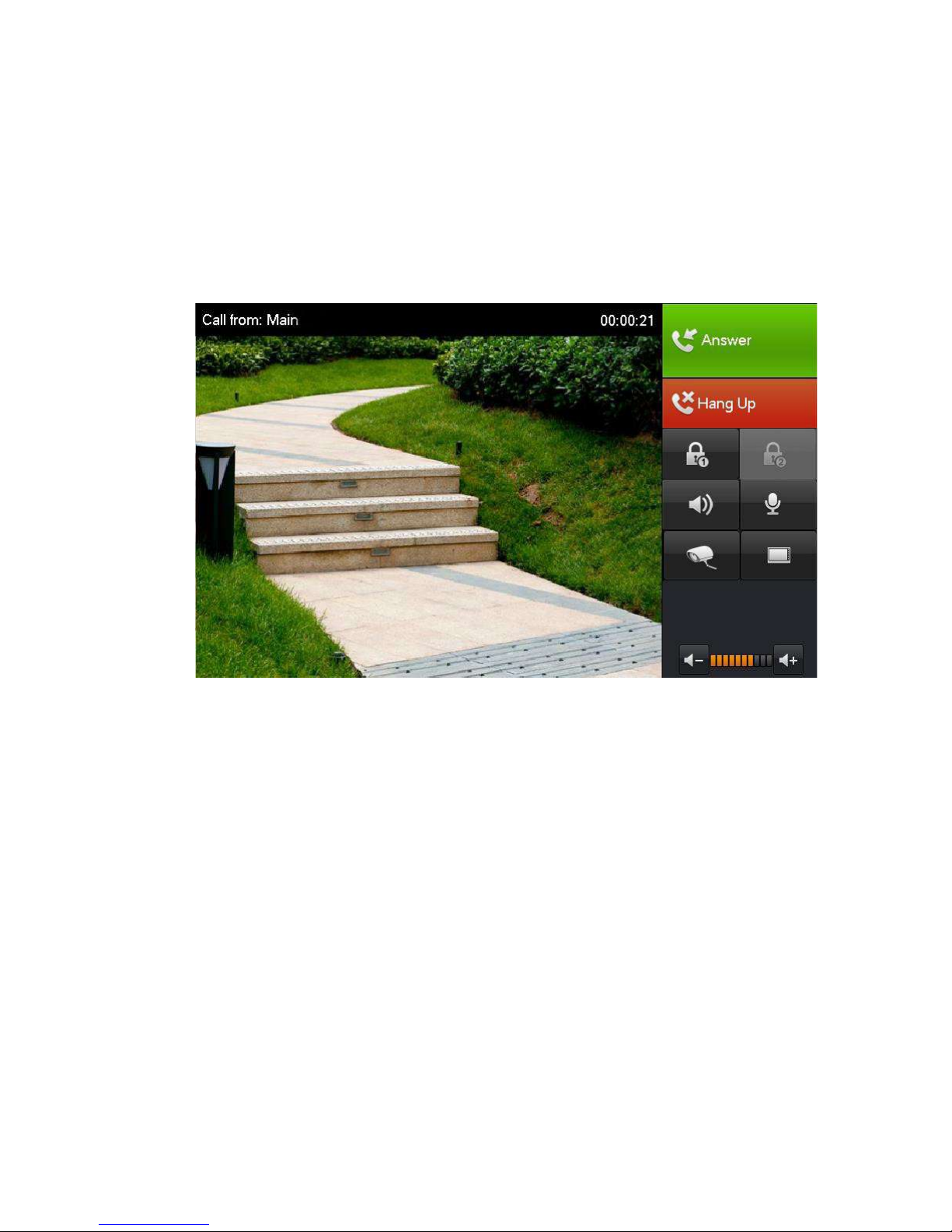
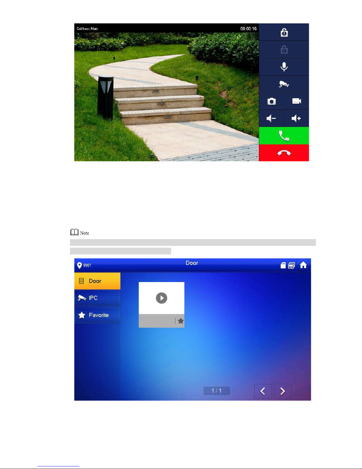
Press call key at VUO, to call VUH. VUH pops up monitoring image and operating keys, as
shown in Figure 5-23. It represents success fu l debugging.
The following figure mean s t hat SD card has been inserted into VUH. If SD card is not ins er t ed,
recording and snapshot ic ons ar e gr ay.
Page 50
40
Figure 5-23
5.2.2.2 VUH Monitors VUO
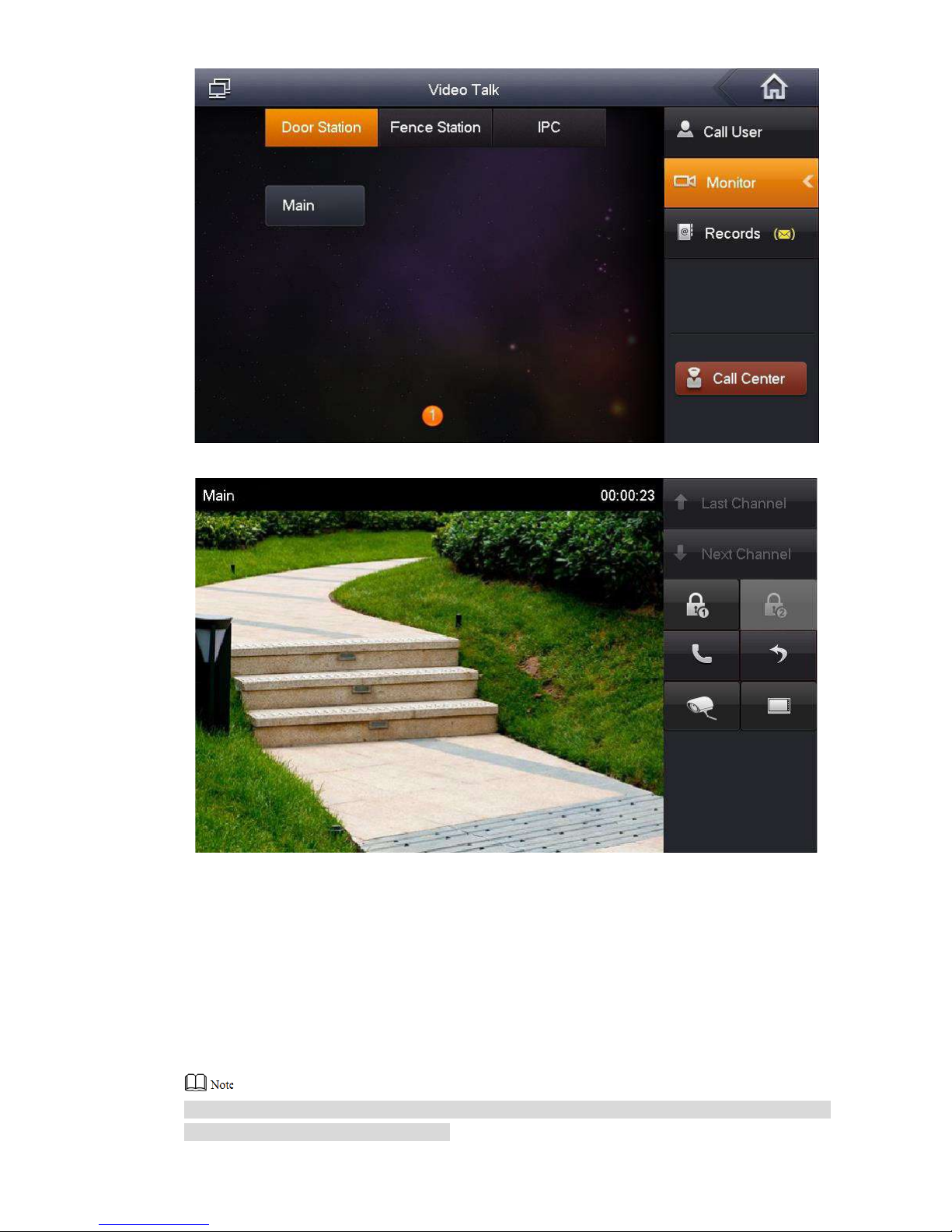
VUH is able to monitor VUO, fence station or IP C. Take “VUO” for example.
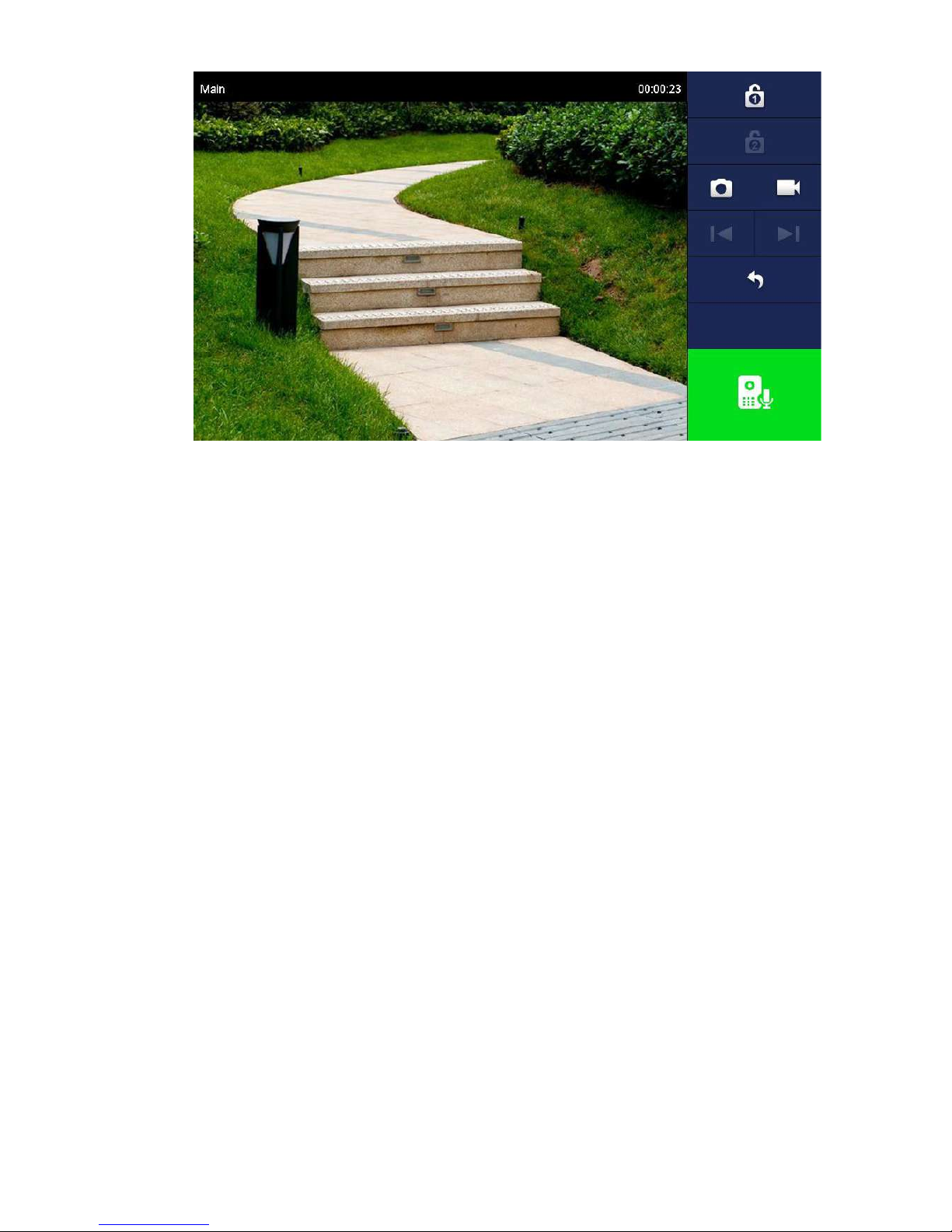
Select “Monitor > Door”, as show n in Figure 5-24. Select the VUO to ent er monitoring image,
as shown in Figure 5-25.
The following figure mean s t hat SD card has been inserted into VUH. If SD card is not ins er t ed,
recording and snapshot ic ons ar e gr ay.
Figure 5-24
Page 51
41
Figure 5-25
Page 52
42
6.1
Call Function
6.1.1
Call Management Centre
Press the call key of VUO within the set time period, to call management c ent r e only and
realize video talk.
Configure the following par am et er s before calling.
Step 1
Step 2
Step 3
Step 4
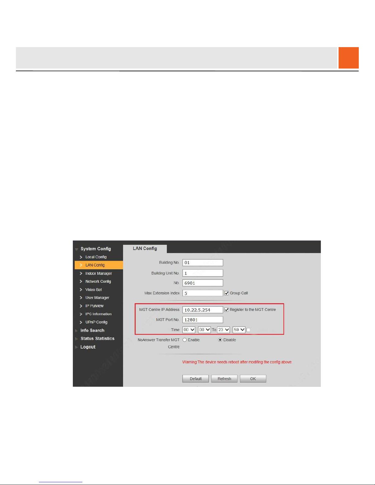
Select “System Config >LAN Config”.
The system displays “LAN Config” interface.
Select “Register to the MGT Ce ntre”; set “MGT Centre IP Addre ss ” and “M GT Port
No.”.
Register the VUO at manage ment center.
Set “Call VUS Time” and sele c t “ Ca ll VUS or Not”.
Enable to call the management c ent r e within the set time period.
Click “OK” to save the settings.
Figure 6-1
6.1.2
Single Call of VUH
Single call applies to the scene where one door corresponds to one VUH. Press the call key of
VUO, to call the VUH directly.
6
Basic Function
Page 53
43
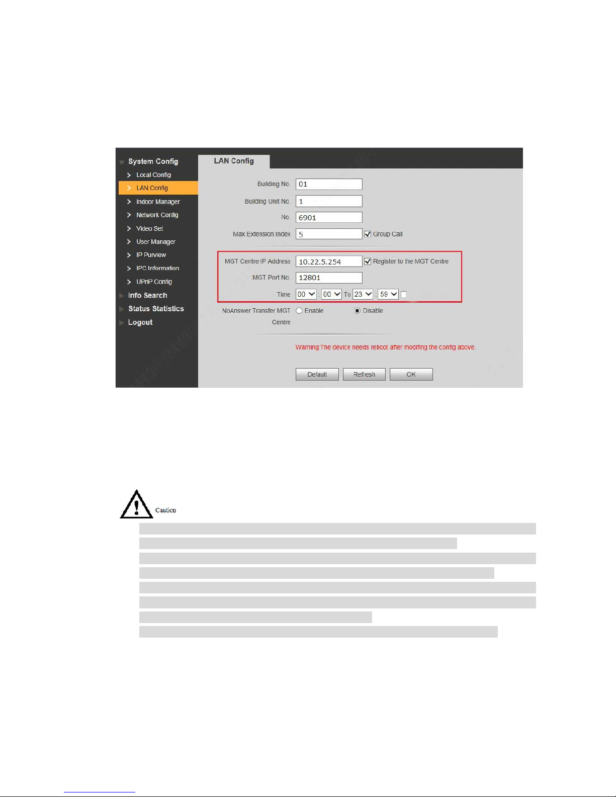
To realize single call function, ensure that VUO doesn’t enable ca ll o f man agement centre.
Specific settings are as follows.
Step 1
Step 2
Select “System Config > LAN Config”.
The system displays “LAN Config” interface.
Confirm if you select “Call TV S or N ot ” .
If it is not selected, press the call key t o call VUH; if it is selected, please cancel the
selection.
Figure 6-2
6.1.3
Group Call
Group call applies to the scene where one door corresponds to multiple VUHs. Press the call
key of VUO, to call multiple VUHs directly.
Please ensure that single call between VUO and VUH works normally. If single call fails,
please check the configur ation by reference to “5.1 Debugging Settings”.
Room no. of extension VUH ends up with “-1, -2…” based on room no. of master VUH.
For example, if master VUH is 9901, the ext ension VUH will be 9901-1, 9901-2…
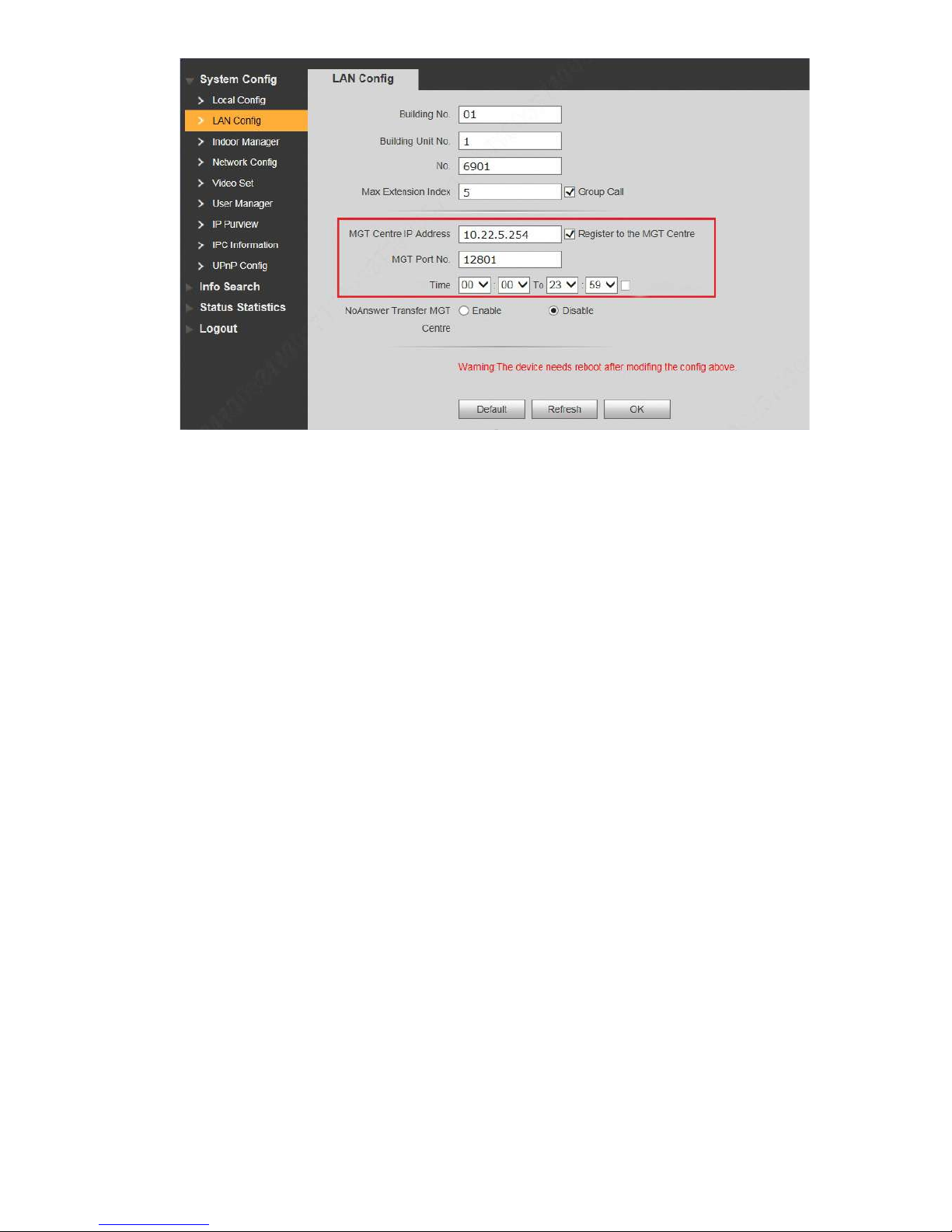
At WEB interface of VUO, select “System Config > LAN Config”, set “Max Extension Index”
and tick “Group Call” to enable group call function. There is one master VUH at most and
five extension VUHs at most, as shown i n Figure 6-3.
Please confirm that “Call VUS or Not” has been can cele d, as show n in Figure 6-3.
Page 54
44
Figure 6-3
6.2
Unlock Function
6.2.1
Remote Unlock at VUH/VUS
When being called, during mon it oring and calling status, the VUO will be unlocked remotely at
VUS or VUH.
6.2.2
Open Door at WEB Interface
Step 1
Step 2
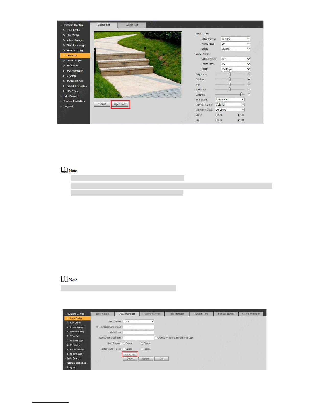
Select “System Config >Vi deo Set>Video Set”.
The system displays “Video Set” interface.
Click “Open Door”, and VUO is unlocked, as show n in Figure 6-4.
Page 55
45
Figure 6-4
6.2.3
Unlock with IC Card
Swipe the authorized IC car d at VUO, so as to open the door.
Only some mod els o f devices support this function.
Authorized IC card refers to a card that is issued and authorized to open the door. For card
issuing operation, please refer t o “6.3 Issue Card”.
6.2.4
Unlock with Exit Button
If VUO is connected with exit button, pres s the exit button to open the door.
6.3
Issue Card
Authorize IC card at VUO WEB interface, so the user can open door with authorized card.
Some models of devices don’t support this function.
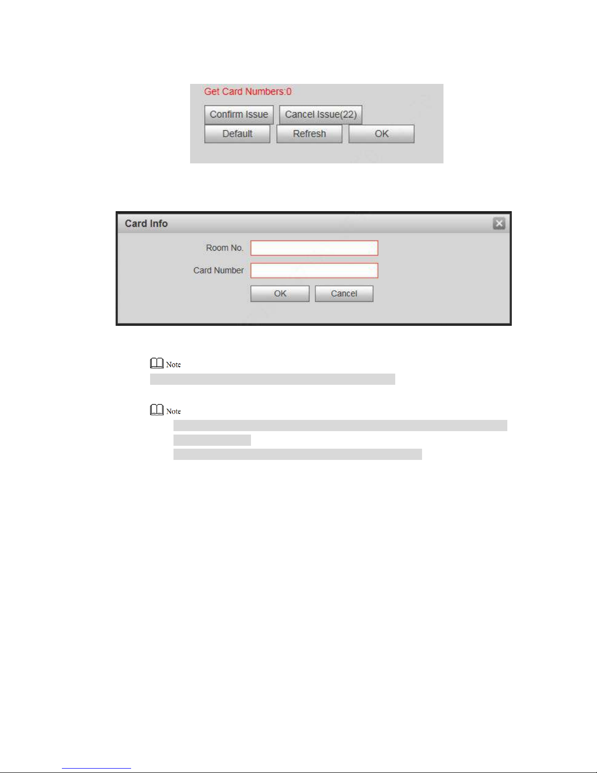
Step 1 Select “System Config >Local Config > A&C Manager”.
The system displays “A&C Manager” interface, as shown i n Fi gur e 6-5.
Page 56
46
Step 2 Click “Issue Card”.
Figure 6-5
The system displays 30s countdown, as shown in Figure 6-6.
Step 3
Step 4
Step 5
Figure 6-6
Within 30s countdown, swipe a n unauthorized card at VUO.
The system pops up “Card I nfo” i nterface, as shown in Figure 6-7.
Figure 6-7
Enter “Room No.” and “Car d No.” .
Cards can be swiped continuously, within a period of 30s.
Click “OK” to finish issuing card.
Click “OK” w ithin t he countdown, so the cards will be valid. Otherwise, all card
info will be invalid.
Click “Cancel” when issuing cards, in order t o st op issuing.
6.4
Monitoring Function
Both VUS and VUH can monitor the VUO.
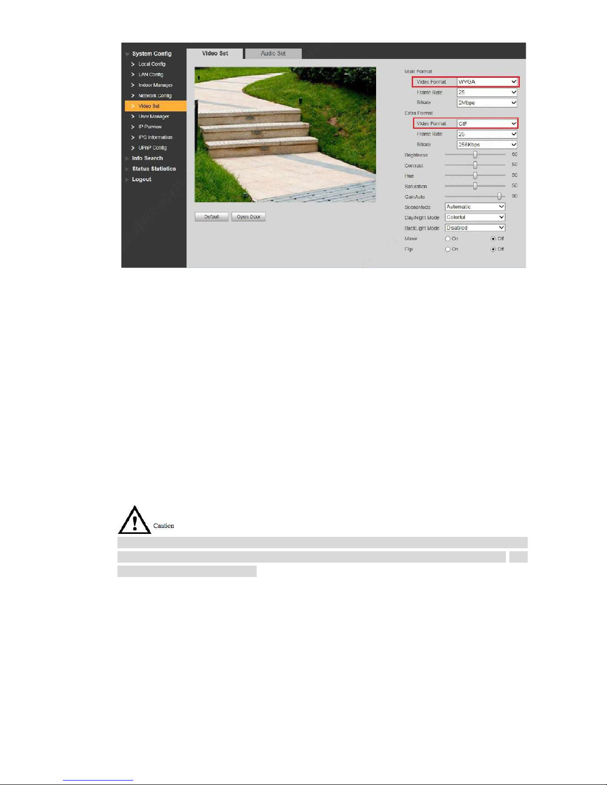
VUO supports multi-c hannel stream monitoring. Av ail able channels vary under different video
formats. Support max. 4 channels with 720P, and support max. 6 channels with WVGA.
Video format is set as follows:
Step 1
Step 2
At VUO WEB interface, select “System Config >Video Set>Video Set”.
The system displays “Video Set” interface.
Select “Video Format”.
Page 57
47
Figure 6-8
6.5
Tamper Switch
VUO is equipped with a tamper switch against the wall. In case that the device is
disassembled from the wall, tamper switch will leave the wall too. The device will emit tamper
alarm sound and report alar m info to management centre.
6.6
Restore Backup
If VUH info or card no. info is modified by mis-operation during use, two restoration ways are
available to restore them.
VUO saves VUH info of the system automatically every half an hour. If VUH info is modified by
mis-operation, please restore them timely. Otherwise, the system will automatically save misoperation info after half an hour.
Restore from backup data in device memory
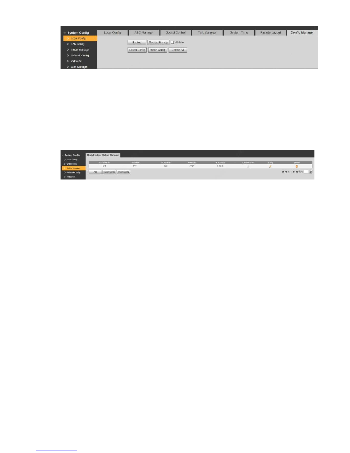
Step 1 Select “System Config >Local Config > Config Manager”.
The system displays “Config M anager” interface, as shown in Figur e 6-9.
Page 58
48
Step 2
Figure 6-9
Select “VUH Info” and click “Restore Backup”.
Backup VUH info in the device will be restored to VUO.
Restore from local backup data
Step 1
Step 2
Step 3
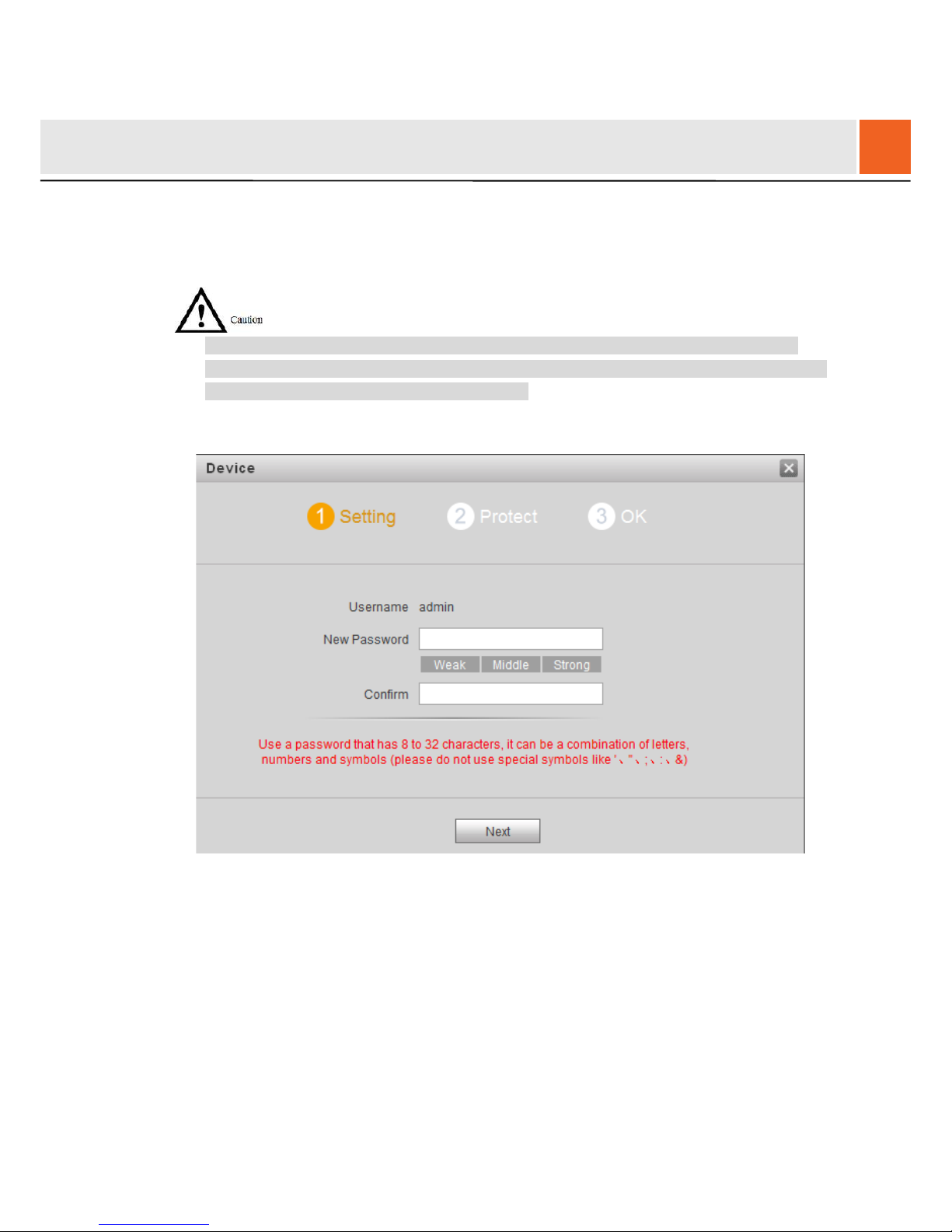
Select “System Config >In door M anager”.
The system displays “Digital Indoor Station Manager” int er fa ce, as shown in Figure 6-
10.
Figure 6-10
Click “Import Config”. The system displays “Open” interface.
Select config files (.log) and cl ic k “Open”.
The system displays “Succ ess” t o complete importing config.
Page 59
49
7.1
Initialization
For the first log in or l ogin after restoring factory def aults, please initialize WEB interface.
Please ensur e that default IP addresses of PC and VUO are in the same net w or k segment.
Otherwise, it fails to enter initialization interface.
Step 1
Step 2
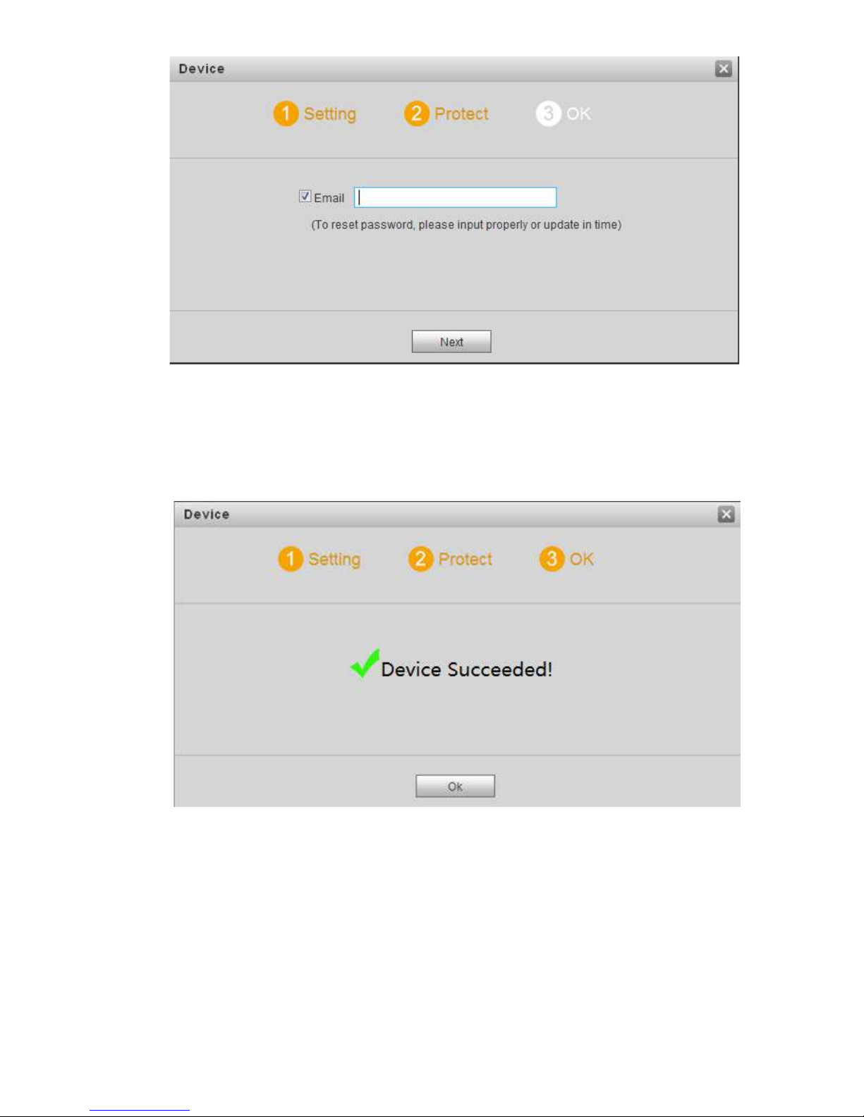
Enter default IP address of VUO at the address bar of PC browser, and press [Enter] key.
The system displays “Setting” interface, as shown in Fig ur e 7-1.
Figure 7-1
Enter “New Password” and “ Confirm”, and click “Next”.
The system displays “Protect” interface, as shown in Figure 7-2.
This password is used to login WEB interface. It shall be at least 8 char acters, and shall
include at least two types of num ber , letter and symbol.
7
WEB Config
Page 60
50
Step 3
Step 4
Figure 7-2
Select “Email” and enter your Email address.
This Email address is used t o r eset t he pas sw or d, so it is recommended that it s houl d be
set.
Click “Next”. The system displays “OK” interface, as shown in Figure 7-3, and shows
“Device succeeded !”
Step 5 Click “OK”.
Figure 7-3
The system displays WEB login interface.
7.2
Reset the Password
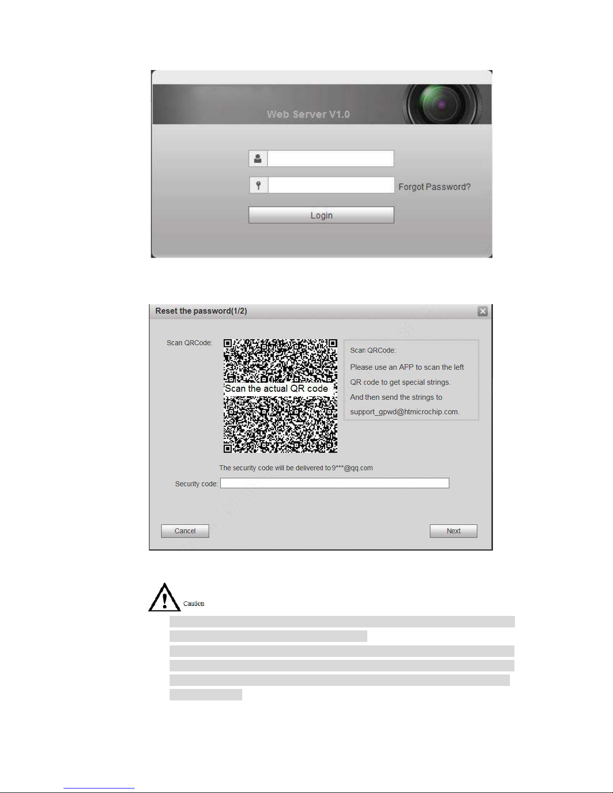
If you forget login passwor d of ad m in user, please reset the login password by scanning QR
code.
Page 61
51
Step 1 Enter IP address of VUO at the address b ar of PC browser, and press [Enter] key.
The system displays login int er fa ce, as shown in Figure 7-4.
Step 2 Click “Forgot Password”.
Figure 7-4
The system displays “Reset the password” dialog box, as shown in F igure 7-5.
Step 3
Step 4
Step 5
Figure 7-5
Scan the QR code accordi ng t o interface prompts and obtain security code.
Two securit y codes can be obtained by scan ni ng t he same QR code. To obtain
security code again, please r efresh QR code.
After receiving security code in your Email, ple ase reset the password with the
security code within 24 hours. Otherwise, the security code will become invalid.
If wrong secur ity code is entered for 5 times continuously, this account will be
locked for 5 min.
Please enter the received security code in the dialog box.
Click “Next” .
Page 62
52
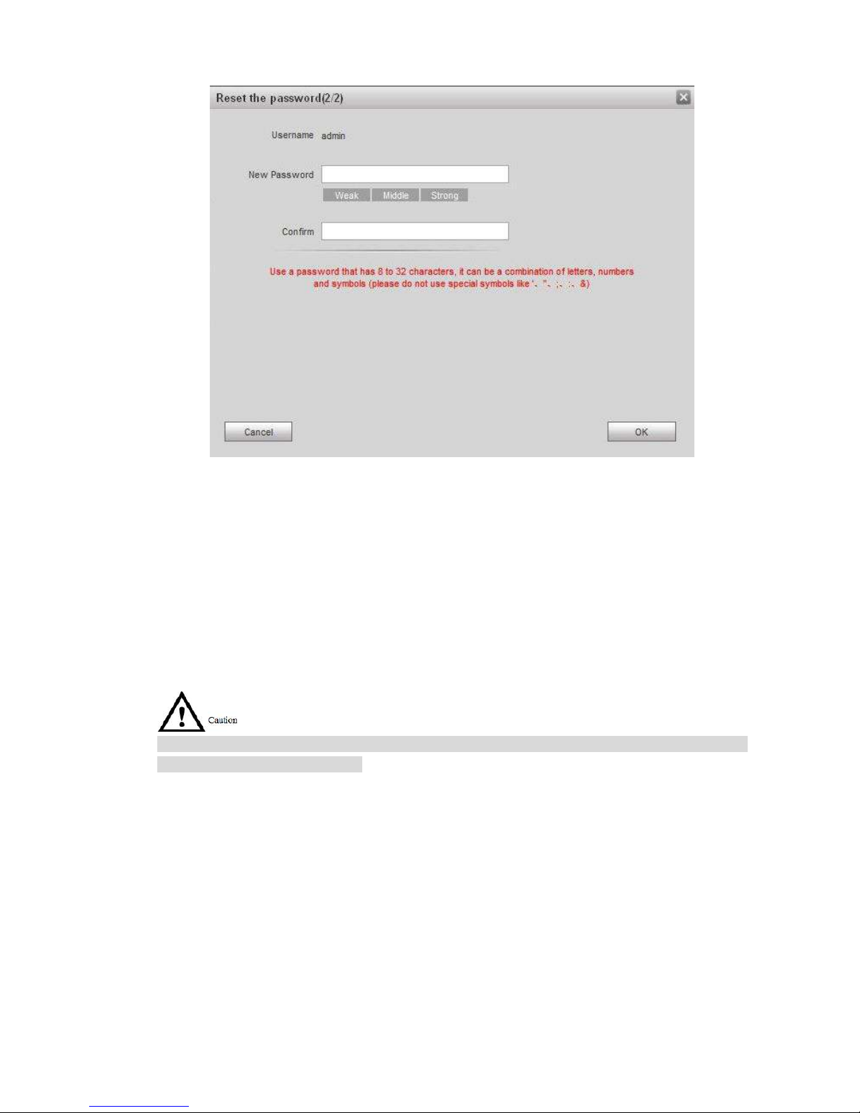
The system displays new passw or d setting interface, as shown in Figure 7-6.
Step 6
Step 7
Figure 7-6
Set “New Password” and “Confirm”.
Password can be 8 to 32 non-null characters; it consists of letters, numbers and symbols
(except “'”, “"”, “;”, “:” and “& ”). The password shall consist of 2 types or over 2 types.
Please set a high-security password according to passw ord s t r engt h prompt.
Click “OK” to complete resetting.
7.3
System Login
Please ensure that IP addres ses of PC and VUO are in the same networ k se gment; otherwise, it
fails to enter WEB login interface.
Step 1 Enter IP address of VUO at the address b ar of PC browser, and press [Enter] key.
The system displays WEB login interface, as shown in Figur e 7-7.
Page 63
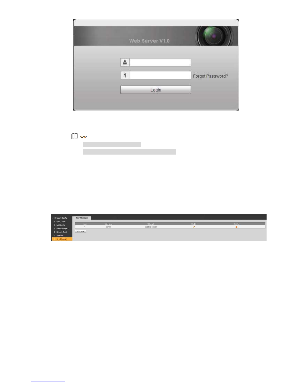
53
Step 2
Figure 7-7
Enter username and password, and click “Login”.
Log in the WEB interface of the device.
Default userna me is admin.
Password is the one set during initialization.
7.4
User Manager
Add, delete and modify WEB user info.
Select “System Config > User M anager”. The system display s “ User Manager” interface, as
shown in Figure 7-8.
Figure 7-8
7.4.1
Add User
The added user enjoys all operating authorities except add ing u s er and admin user
management.
Step 1 Click “Add User”.
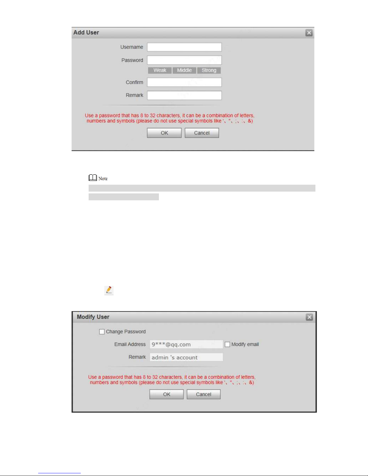
The system displays “Add User” int erface, as shown in Figure 7-9.
Page 64
54
Step 2
Step 3
Figure 7-9
Enter “Username”, “Password”, “Confirm” and remark.
Password is required to be at least 8 characters, and shall include at l east two types of
number, letter and symbol.
Click “OK” to complete addin g.
7.4.2
Modify User
7.4.2.1 Modify Admin User
Admin user can modify his/ her own user password and Email ad dr ess. Email address is used to
reset the password and receiv e in fo.
Step 1 Click in t he l ine o f admin user info.
The system displays “Modify User” interface, as show n in F igure 7-10.
Step 2 Modify user info.
Figure 7-10
1. Tick “Change Password”.
Page 65
55
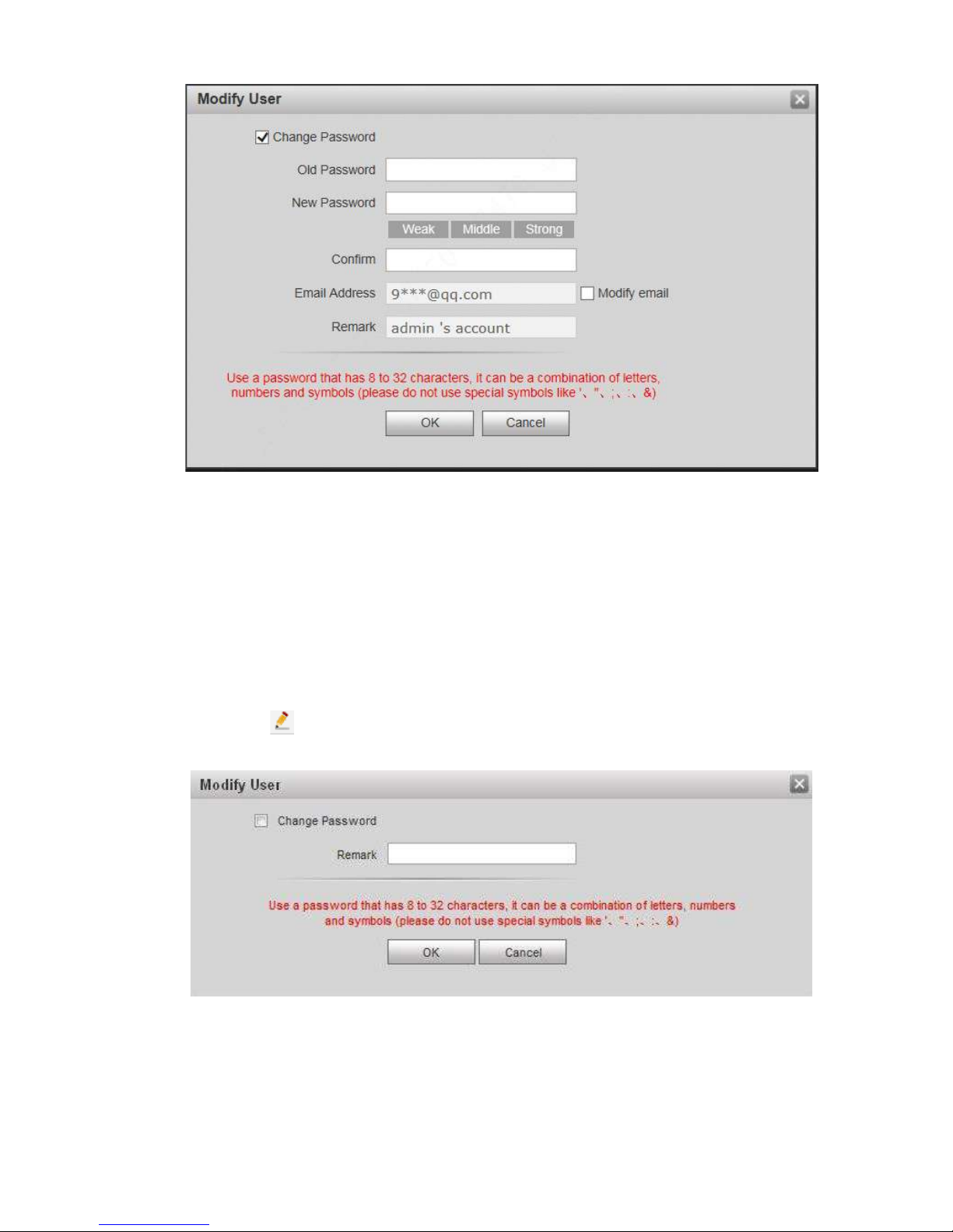
The system displays password change interface, as show n in Figure 7-11.
Figure 7-11
2. Enter “Old Password”, “New Passwor d” and “Confirm”.
3. Tick “Modify Email” to enter Email address.
4. Click “OK”.
7.4.2.2 Modify Ordinary User
Ordinary user refers to other uses except admin user. Admin user can modify remark and
password of all other users, while ordinary user can modify his/her own password only. Take
admin user modifying ordinar y user for example.
Step 1
Step 2
Click in the line of ordinary user info.
The system displays “Modify User” interface, as show n in F igure 7-12.
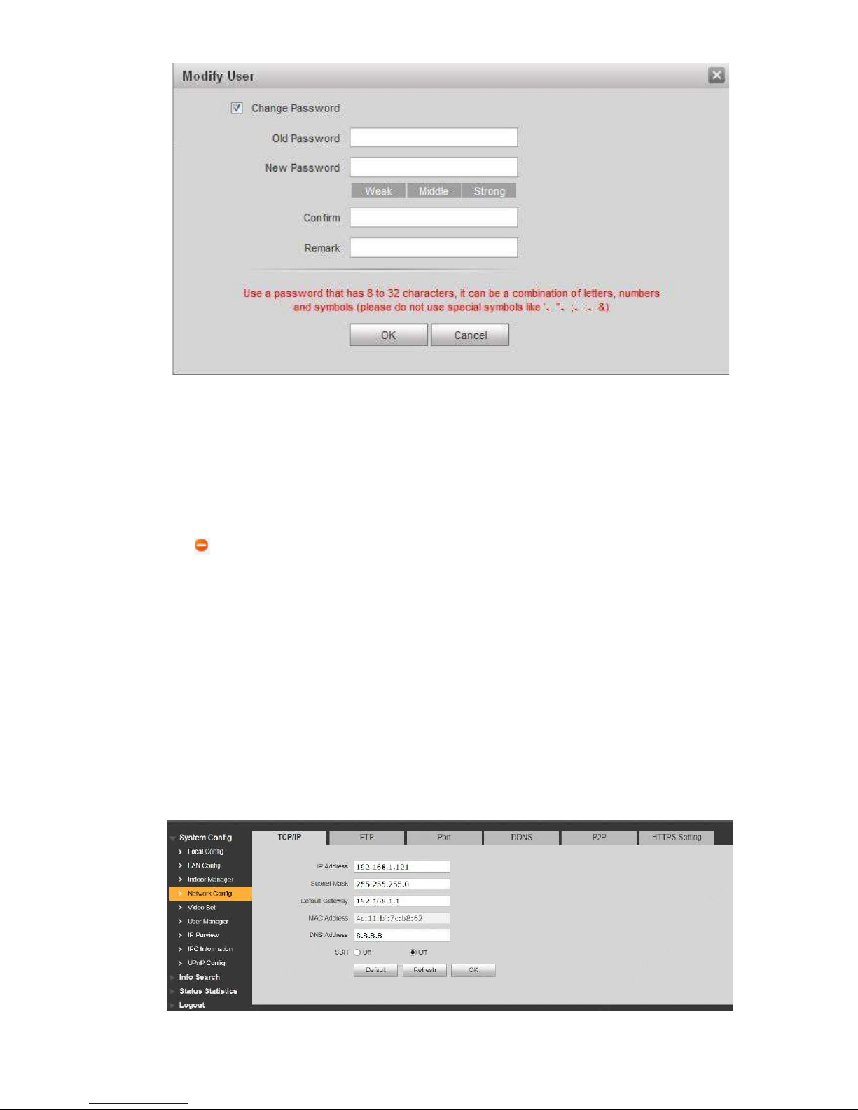
Figure 7-12
Modify user info, as shown in F igure 7-13.
1. Tick “Change Password”.
The system displays password change interface, as show n in Figure 7-13.
Page 66
56
Figure 7-13
2. Enter “Old Password”, “New Passwor d” and “Confirm”.
3. Update remark.
4. Click “OK”.
7.4.3
Delete User
Click in the line of user info that requires deletion, in order to delete this user.
7.5
Network Paramet er Config
Set IP address, FTP server , application port, DDNS, HTT PS, UPnP and IP authority.
7.5.1
Network Config
Set IP address of VUO.
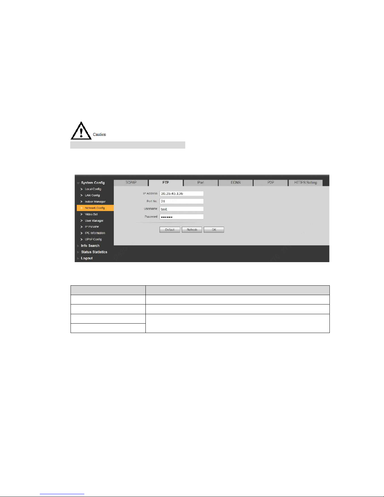
Step 1 Select “System Config > Network Config > TCP/IP”.
The system displays “TCP /IP” interface, as shown in Figure 7-14.
Page 67
57
Step 2
Step 3
Step 4
Figure 7-14
Enter the planned “IP Addres s” , “ Subnet Mask” and “Default Gatew ay”.
Turn on SSH according to needs.
After SSH is on, Telnet and other debugging terminals can connec t VUO, operate and
debug it.
Click “OK” to save the settings.
7.5.2
FTP Server
Set FTP server, so recordi ngs and snapshots will be saved in F TP server.
Please obtain FTP server in fo in advance.
Step 1
Step 2
Select “System Config > Network Config > FTP”.
The system displays ““FT P” int erface, as shown in Figure 7-15.
Figure 7-15
Set the parameters and refer to Table 7-1 for details.
Parameter
Description
IP Address
IP address of the host to instal l F TP server.
Port No.
It is 21 by default.
Username
Username and password t o visit FTP server.
Password
Step 3
7.5.3
Port
Table 7-1
Click “OK” to save the settings.
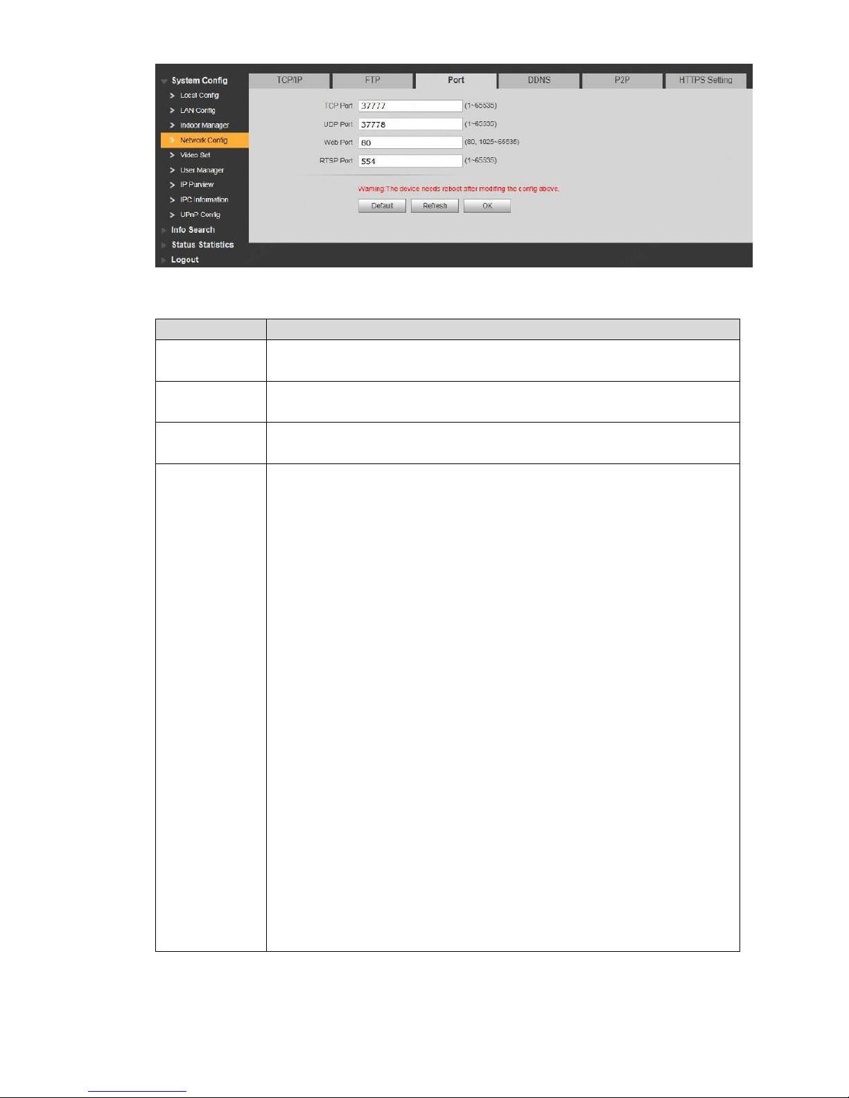
Set the port to visit WEB interface of VUO.
Step 1 Select “System Config > Network Config > Port”.
The system displays “Port” inter face, as shown in Figure 7-16.
Page 68
58
Step 2
Figure 7-16
Set port value of this device and re fer t o Table 7-2 for details.
Parameter
Description
TCP Port
Communication port of TC P pr ot ocol, to be set according to the user’ s actual
needs. It is 37777 by default.
UDP Port
User datagram protocol p or t , to be set according to the user’s actua l needs.
It is 37778 by default.
Web Port
Port to visit WEB interface of VUO, to be set ac cording to the user’s actual
needs. It is 80 by default.
RTSP Port
Default RTSP port no. is 554, which can be left unfilled if it is default.
The user plays real-time monitoring with Apple browser QuickTime or
VLC. Blackberry mobile p hones also support this function.
URL format of real-time monitoring stream: to request RTSP streaming
se
rvice of real-time monitoring, please designate the requested channel
no. and stream type in URL. In case of need for certification info, plea
se
pr
ovide username and password.
To visit with Blackberry mobile phones, set s t r eam coding mode to be
H
.264B and resolution to be CIF. Turn off audio.
URL format is described as follows:
rtsp://username:password@ip:port/cam/realmonitor?channel=1&subtype=0
Username: username, such as admin.
Password: pass w ord, such as admin.
IP: device IP, such as 10.7.8.122.
Port: port no. , which is 554 by default. It can be left unf il le d if it is
default.
Channel: cha nnel no. starting with 1. If channel is 2, channel=2.
Subtype: str eam type. Main stream is 0 (subtype=0), while extra stream
is 1(subtype=1).
For example, to request ext r a st r eam o f channel 2 of a device, URL is as
follows:
rtsp://admin:[email protected]:554/cam/realmonitor?channel=2&subtype=
1
If certification is unneeded , it is unnecessary to designated user name and
password. Use the following format:
rtsp://ip:port/cam/realmonitor?channel=1&subtype=0
Step 3
Table 7-2
Click “OK” to save the settings.
In case that the port is modified, ent er “http://VUO IP: WEB port no.” in the browser, to
Page 69
59
visit WEB interface of this VUO.
7.5.4
DDNS Server
In case of frequent changes in IP address of the device, DDNS (Dynamic Domain Name Server)
dynamically updates the relation between domain name and IP address on DNS server, and
ensures that users are able to visit the device through domain nam e.
Before configuratio n, ple ase check if the device supports DDNS server; login corresponding
DDNS website to register username, password and domain name info.
After the user registers successfully on DDNS website and logins, view the registered user’s
all connected devices.
Step 1
Step 2
Step 3
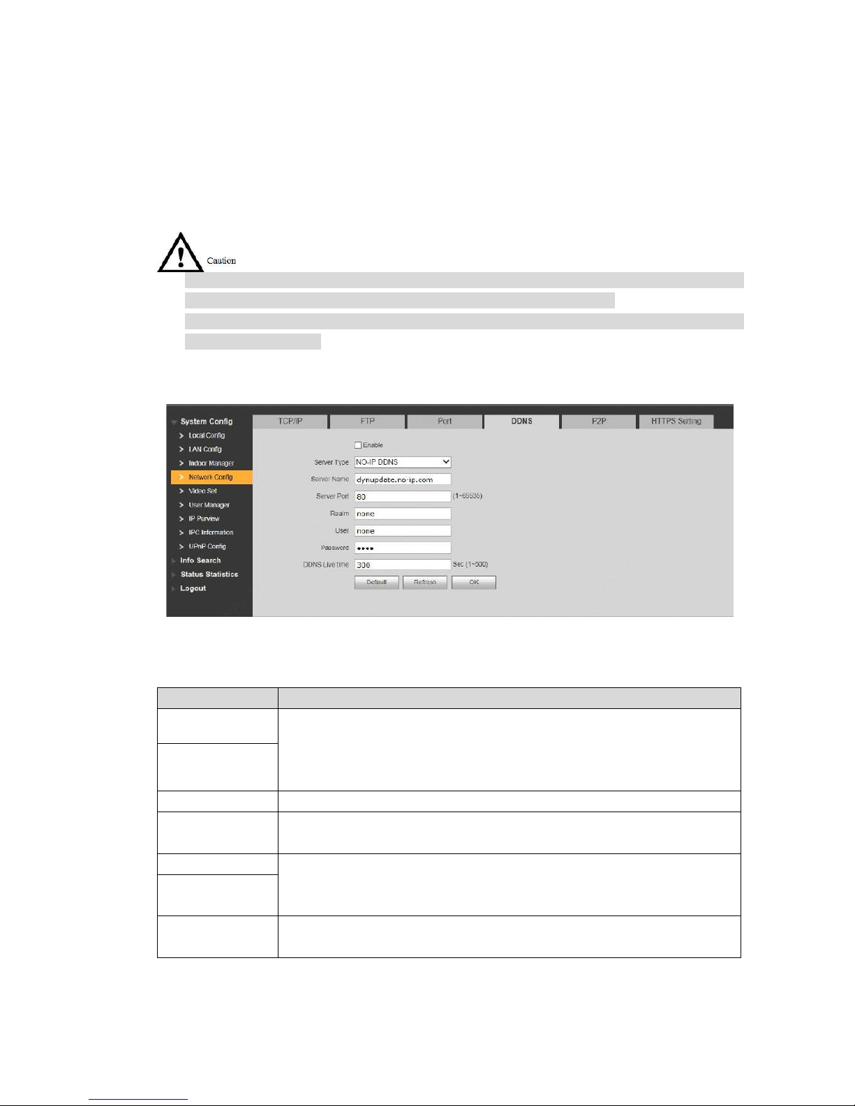
Select “System Config > Network Config > DDNS”.
The system displays “DDNS” inter f ac e, as shown in Figure 7-17.
Figure 7-17
Tick “Enable” to enable DD NS server function.
Set parameters and refer t o Table 7-3 for details.
Parameter
Description
Server Type
Server type refers to name of DD N S ser ver provider. Relation between
server type and server name is as follows.
Dyndns DDNS address is: members.dyndns.org.
NO-IP DDNS address is: dynupdate.no-ip.com.
Server Name
Server Port
Port no. of DDNS server.
Realm
Domain name registered by the user at the website of DDNS server
provider.
User
User name and password obt ained from DDNS server provider. The user
needs to register (includin g user name and password) at the w ebsite of
DDNS server provider.
Password
DDNS Live Time
The time interval to raise updat e request after designated DD N S update is
enabled. The unit is second.
Step 4
Table 7-3
Click “OK” to save the settings.
Enter domain name in the browser and press [Enter] key. Con fi guration has succeeded if
Page 70
60
WEB login interface of the device is displayed, and configur at ion has failed if WEB login
interface is not displayed.
7.5.5
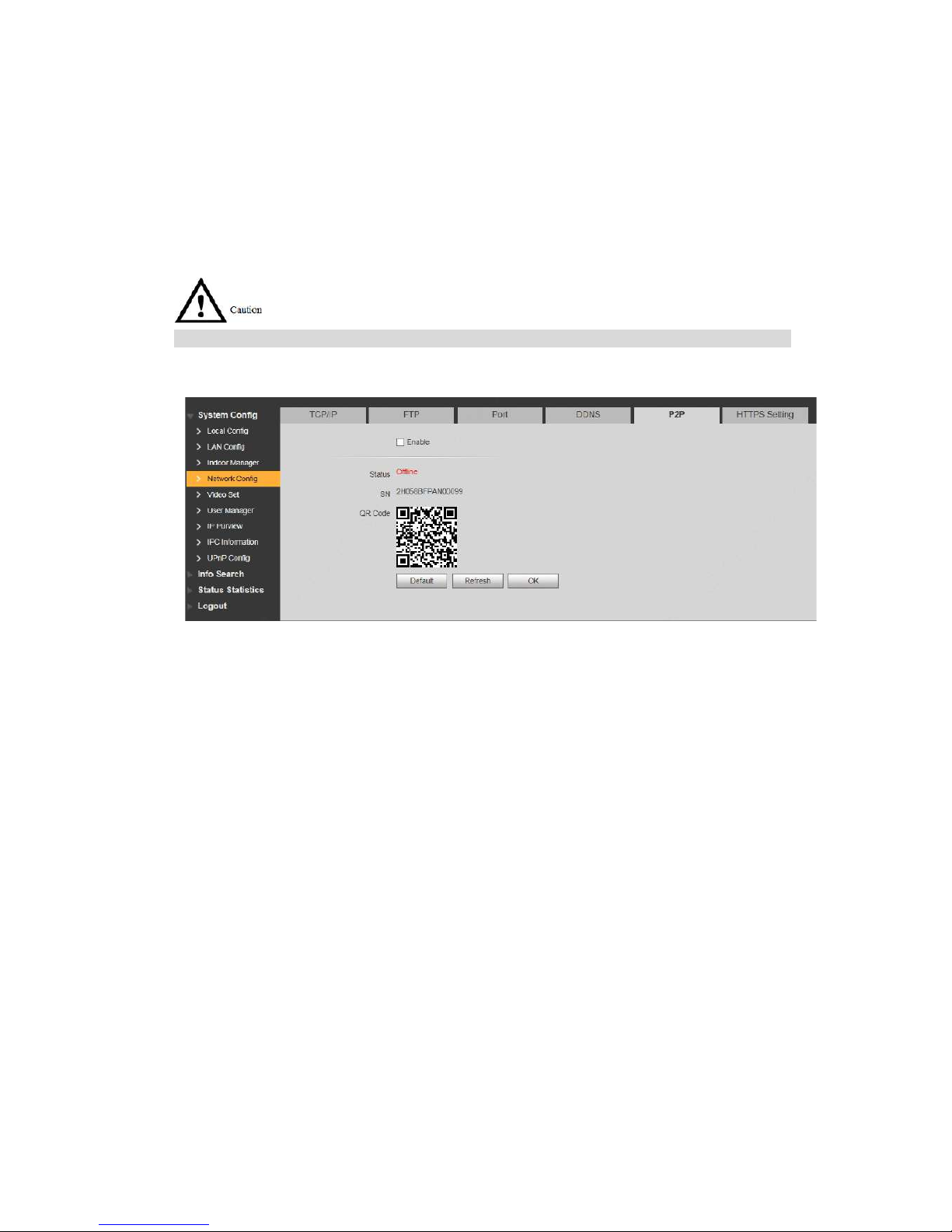
P2P
P2P is a private network traversal technology. After enabling P2P function, open mobile client
software, enter the serial number directly or scan the QR code to obtain serial number, and thus
manage multiple controllers. During easy and convenient use, it is unnecessary to apply for
dynamic domain name, ca r r y out port mapping or deploy relay server.
To use this function, the dev ice shall be connected with Internet , in order t o use it normally.
Step 1
Step 2
Step 3
Step 4
Select “System Config > Network Config > P2P”.
The system displays “P2P” inter fa ce, as shown in Figure 7-18.
Figure 7-18
Tick “Enable” to enable P2P function.
Select “P2P Server”.
Click “OK” to complete set t ing.
After the setting has been comp let ed, “ St at us” becomes “Online”, representing
successful P2P registration.
After successful P2P registration, scan QR code with mobile client or enter the serial number
directly to add VUO, in order to visit and manage VUO.
7.5.6
HTTPS Setting
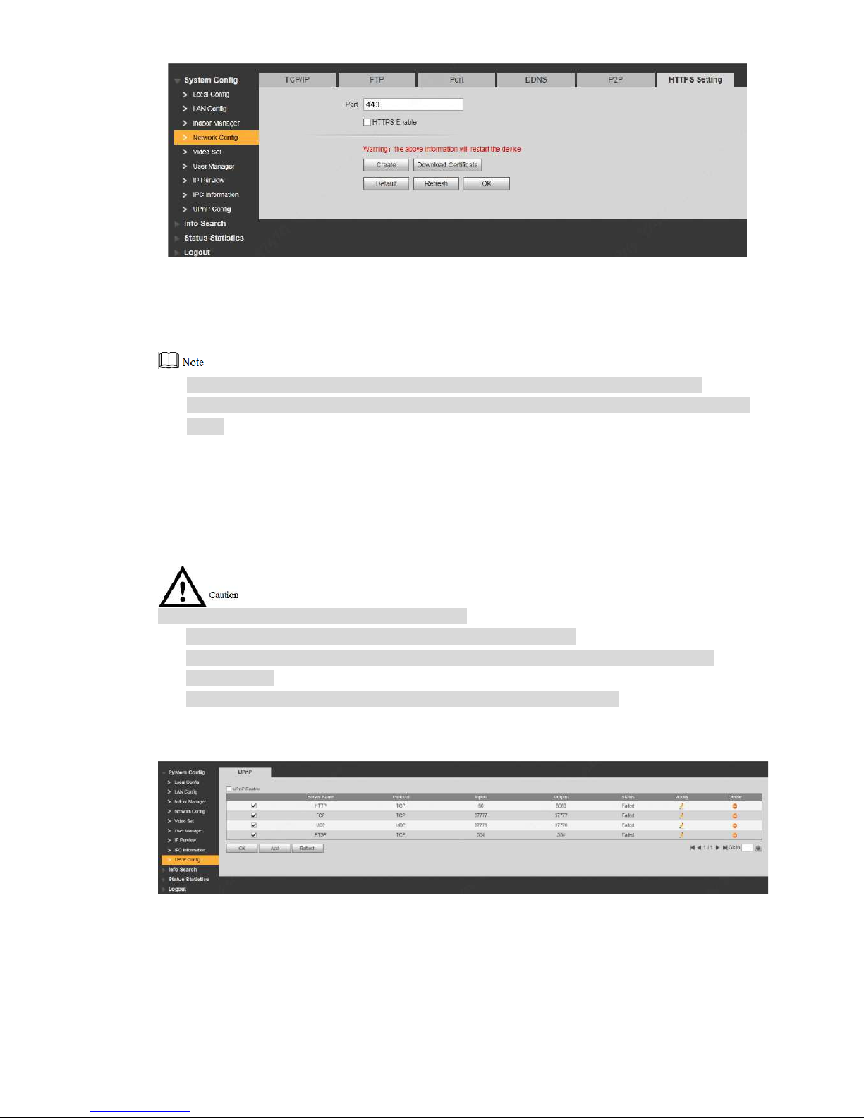
At HTTPS setting interface, create server certificate or download root certificate and set port
number, so PC is able to login through HTTPS. In this way, ensure communication data security;
guarantee user info and device security with reliable st able technology.
Step 1 Select “System Config > Network Config > HTTPS Settin g” .
The system displays “HTT PS Setting” interface, as shown in Figure 7-19.
Page 71
61
Step 2
Step 3
Figure 7-19
Enter “Port”, tick “HTTPS Ena ble” and thus enable the HTTP S fu nction.
Click “OK” to save the settings.
Enter https://VUO IP: Port No. in the browser and WEB login interf ace w ill pop up.
If you use t his f unction for the first time or chan ge device IP, exe cute “Create” again.
If you use H TTPS for the first time after changin g computer, execut e “ Download Certificate”
again.
7.5.7
UPnP
Via UPnP protocol, create map ping relationship between priv at e network and WAN. WAN user
can visit device in LAN via out er I P addr ess.
Please confirm the followi ng operation before use.
UPnP function is used only when VUO is c onnected with router.
Enable UPn P fu nct ion of the router, set IP address of router WAN port ( WAN IP), and
connect WAN.
Connect the dev ice with router LAN port, and conn ect pr ivate network.
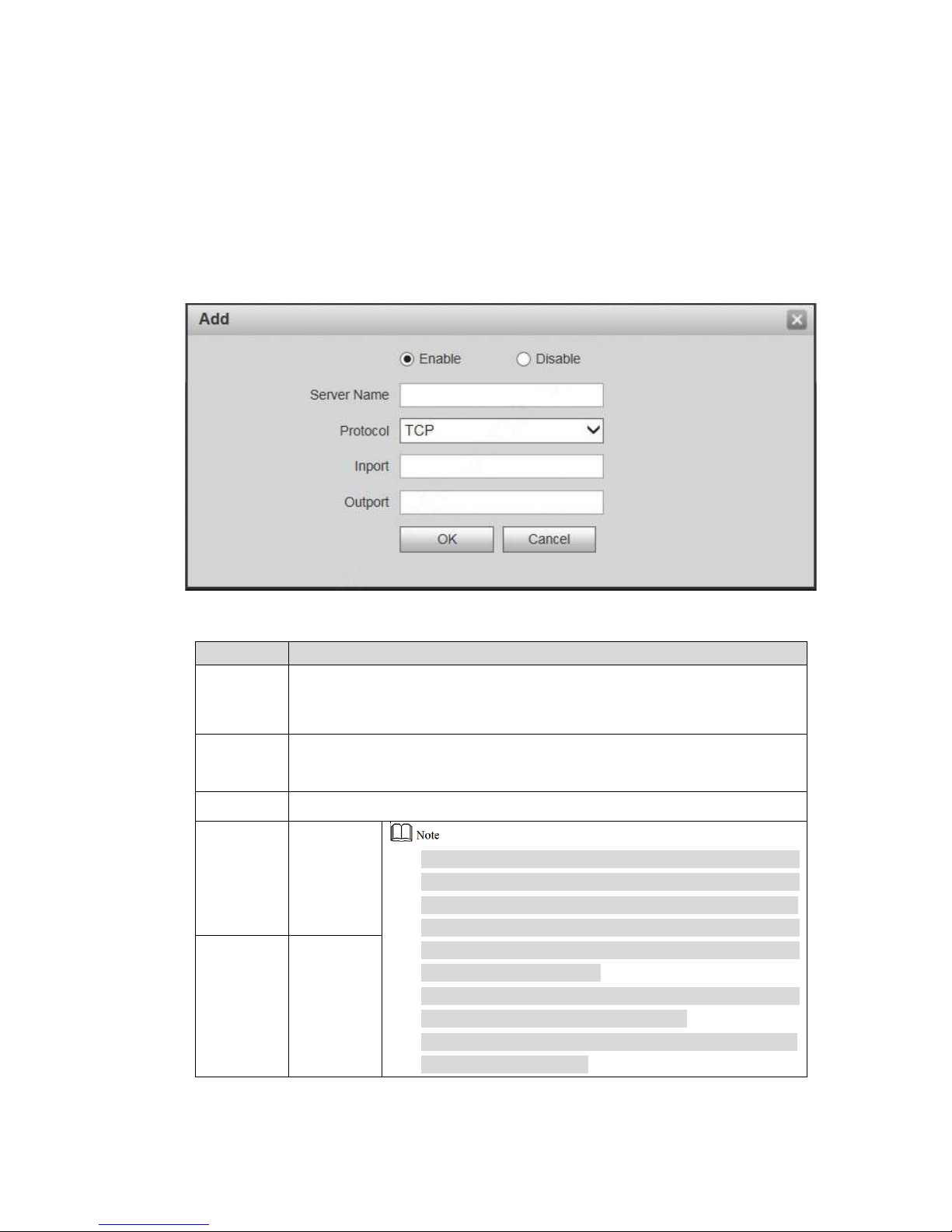
Select “System Config > UPnP Config”, and the system displays “U PnP” interface, as shown in
F
igure 7-20.
Figure 7-20
7.5.7.1 Enable Mapping
There are some mapping relations when leaving factory, which can be used after being enable d.
Step 1 Tick “UPnP Enable” t o enable UPnP function.
Page 72
62
Step 2
Step 3
Select servers to enable mapping relation.
Click “OK” to save the settings.
Enter “http://WAN IP: External Port No.” in the browser, to visit private network device at
corresponding port in the r out er .
7.5.7.2 Add Server
Add new server mapping relat i ons.
Step 1
Step 2
Click “Add”.
The system displays “Add” int erface, as shown in Figure 7-21.
Figure 7-21
Set parameters and refer t o Table 7-4 for details.
Parameter
Description
Enable/
Disable
Tick “Enable” to enable the mapping relation.
Tick “Disable”, meani ng that mapping relation is not enabled. Choose
t
o enable it in the external list.
Server
Name
Name of network server.
Protocol Protocol type.
Inport
Port that
this device
needs to
map.
When you set router mapping outer port, try to use port
within 1024~5000, avoid using well-known port 1~255
and system port 256~1023, in order t o pr event conflicts.
When there are multiple devices in the same LAN,
please plan port mapping, to prevent multi
ple device
mapping to one outer port.
For port mapping in progress, please make sure
mapping port is not occupi ed or limited.
TCP/UDP inports and outports must be identical, and
they cannot be modified.
Outport
Port that is
mapped on
the router.
Step 3
Table 7-4
Click “OK” to save the settings.
Page 73
63
7.5.7.3 Modify Server
Modify server mapping relat ion i n t he l ist .
Step 1
Step 2
Step 3
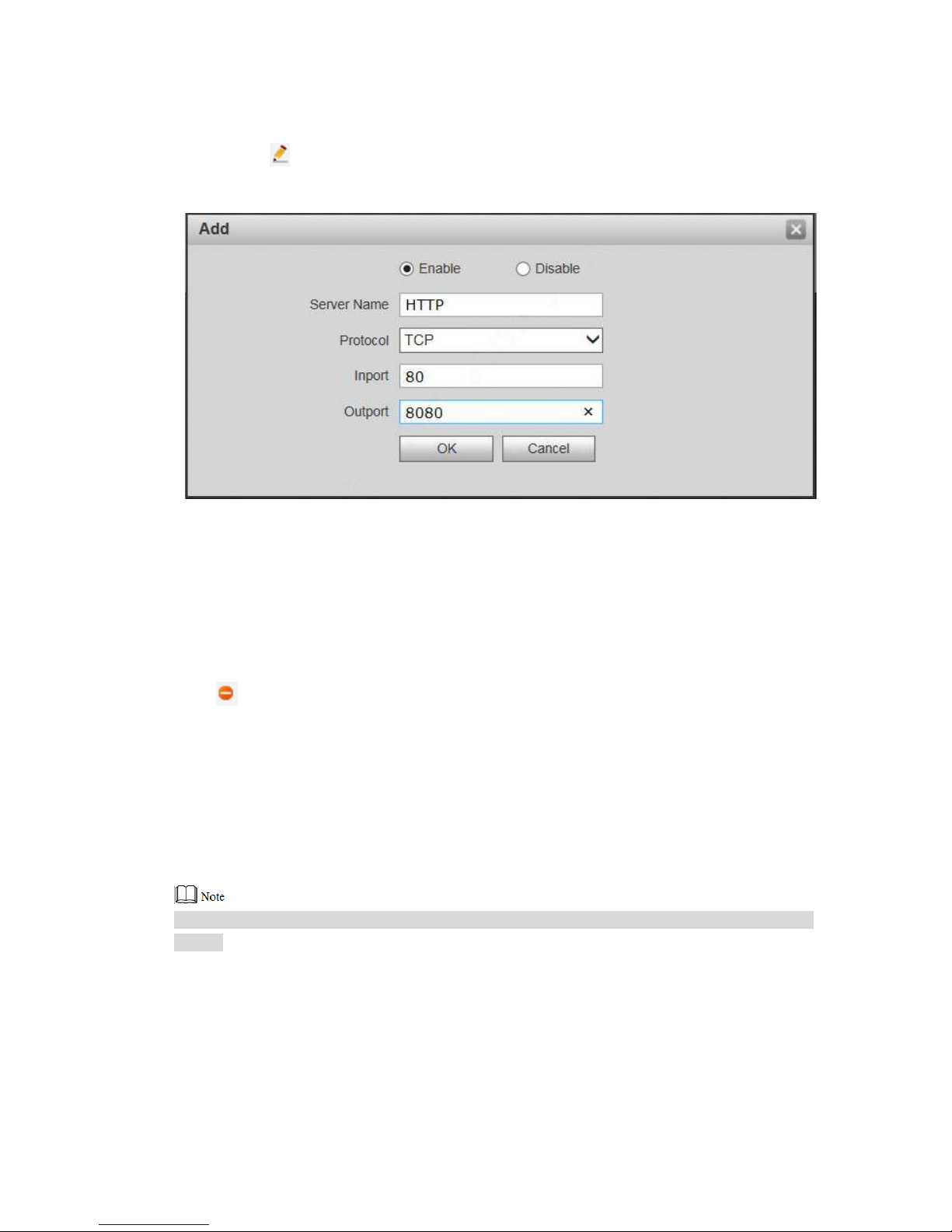
Click .
The system displays “Add” int erface, as shown in Figure 7-22.
Figure 7-22
Set parameters and refer t o Table 7-4 for details.
Click “OK” to save the settings.
7.5.7.4 Delete Server
Delete server mapping relation in the list.
Click to delete mapp ing relation.
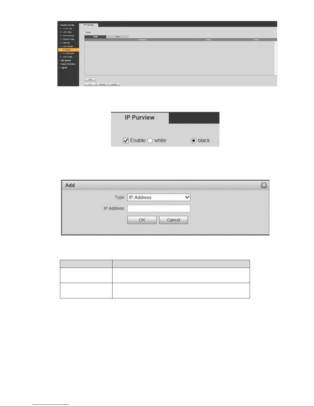
7.5.8
IP Purview
In order to strengthen device network security and protect device data, set access purview of IP
host (IP host refers to personal computer or server with IP) .
White list allows designated IP host to visit the device.
Black list proh ibits designated IP host from visiting the device.
If white list is enabled and set, other IP address, except those in the white list, cannot login the
device.
Step 1 Select “System Config > IP Purview”.
The system displays “IP P ur view” interface, as shown in Figur e 7-23.
Page 74
64
Step 2 Tick “Enable”.
Figure 7-23
The system displays white/black list checkbox, as show n in F ig ur e 7-24.
Figure 7-24
1. Add “White” or “Black”.
2. Click “Add”.
The system displays “Add” int erface, as shown in Figure 7-25.
Figure 7-25
3. Set IP address and refer to Table 7-5 for details.
The system supports to set maximum 64 IP addresses.
Type
Description
IP Address
Add host IP address to be added; adopt IPv4 format, such
as 192.168.1.120.
IP Network Segment
Enter the start address and end address of network
segment to be added.
Table 7-5
4. Click “OK”.
Step 3
Return to IP purview interface.
Click “OK” to save the settings.
IP host in the white list can login WEB interface of the device successfully. The system
displays “Login Failed” if IP host in the black list logins the WEB int er fa ce.
Page 75
65
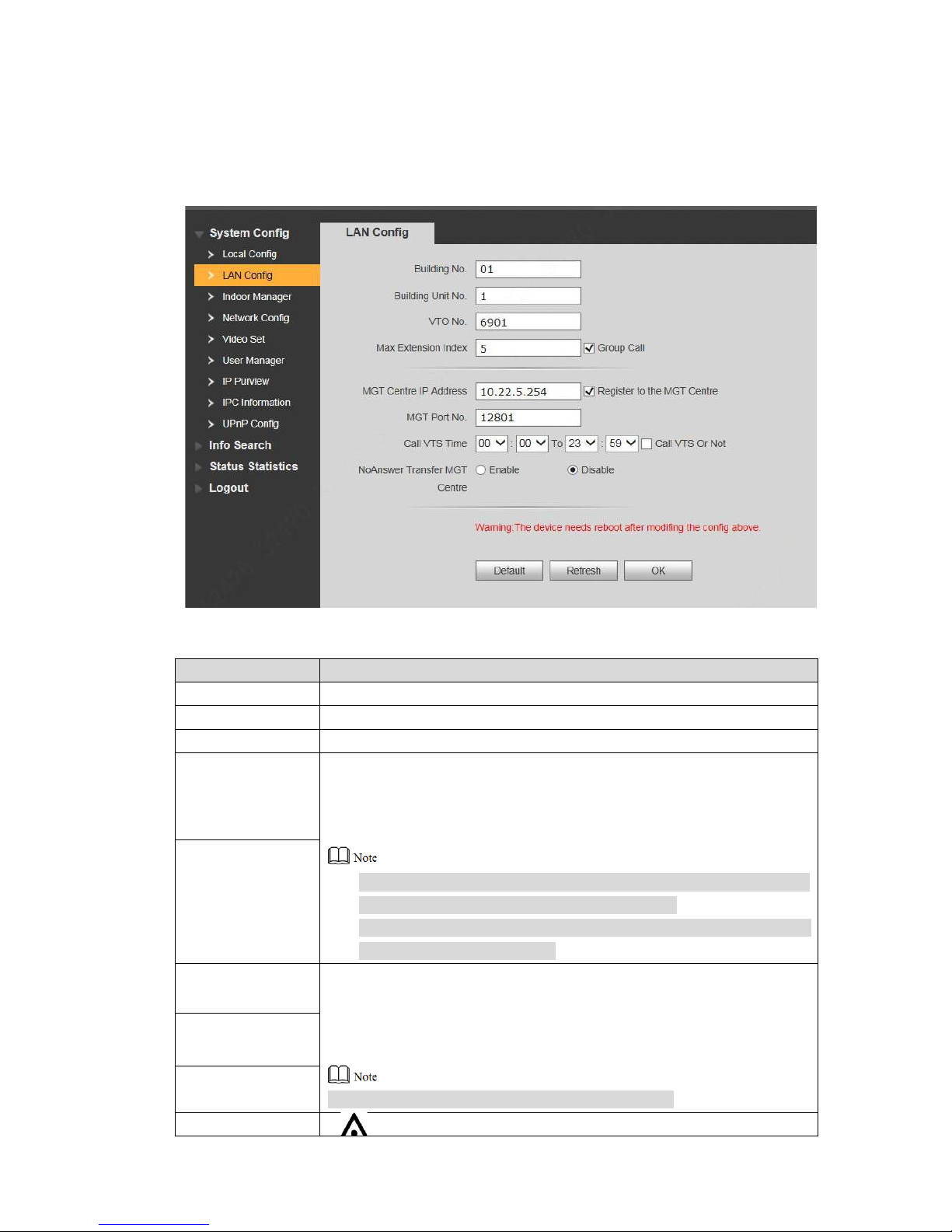
7.6
LAN Config
Set VUO building no., unit no., no., manage me nt centre and group call function.
Step 1
Step 2
Select “System Config > LAN Config”.
The system displays “LAN Config” interface, as shown in F igure 7-26.
Figure 7-26
Set parameters and refer t o Table 7-6 for details.
Parameter
Description
Building No. Set building no. of VUO.
Building Un it No. Set unit no. of VUO.
VUO No.
Set no. of VUO.
Max. Extension
Index
Tick “Group Call” to enable VUO group call function; press the call key
on the VUO, to call master VUH and extension VUH simultaneously.
Max. quantity of group call extension VUH
shall not exceed “Max.
Extension Index”.
After group ca ll function is enabled or disabl ed, t he device reboots
automatically, so the confi gur at io n takes effect.
To realize group call, VUH and VUO shall be set. Please refer to
“6.1.3 Group Call” for details.
Group Call
MGT Centre IP
Set “MGT Centre IP Address” and “ M GT Port No.”; tick “Register t o t he
Address
MGT Centre”. VUO is registered to management centre, so
MGT Port No.
management centre can ma nage the VUO and VUH, and call VUH.
Register to the
MGT Centre
Please obtain management centre info in advance.
Call VUS Time
Page 76
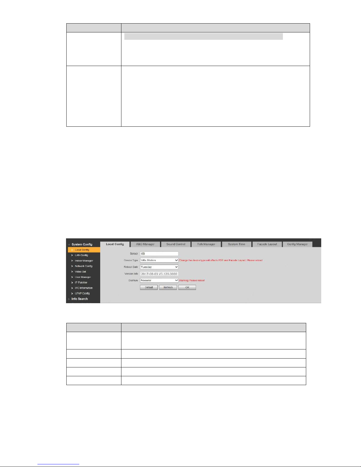
66
Parameter
Description
Call VUS or Not
Ensure that VUO has been registered at m anagement centre.
Set “Call VUS Time” and tic k “C al l VUS or Not”. Pr ess the call key on
the VUO within the set t ime per io d, to call the management centre
only.
No Answer
Transfer MGT
Centre
Tick “Enable” to enable trans ferr i ng t o m anagement centre in case o f
no answer.
In the following cases whe n VUO calls VUH
, the system will transfer the
call to management centre automatically.
SD card has not been inserted into VUH.
SD card has bee n inserted into VUH, but VUO message time is
set to be 0 on the VUH.
Step 3
Table 7-6
Click “OK” to save the settings.
7.7
Local Parameter Config
7.7.1
Local Config
Set info about the device, such as d evice type and reboot date.
Step 1
Step 2
Select “System Config >Local Config> Local Config”.
The system displays “Loc al Config” interface, as shown in F ig ur e 7-27.
Figure 7-27
Set parameters and refer t o Table 7-7 for details.
Parameter
Description
Sensor
If it is dark during video interco m, t ur n on t he f il l-in light automatically.
The larger the value is, the hig her sensitivity becomes.
Device Type
It is villa station by default.
Reboot Date
Set auto reboot time of VUO. It is 2 a.m. on Tuesday by default.
Version Info Display software version number.
Dial Rule Set the user’s dial rule, includin g “ No n-serial” and “Serial”.
Step 3
Table 7-7
Click “OK” to save the settings.
Page 77
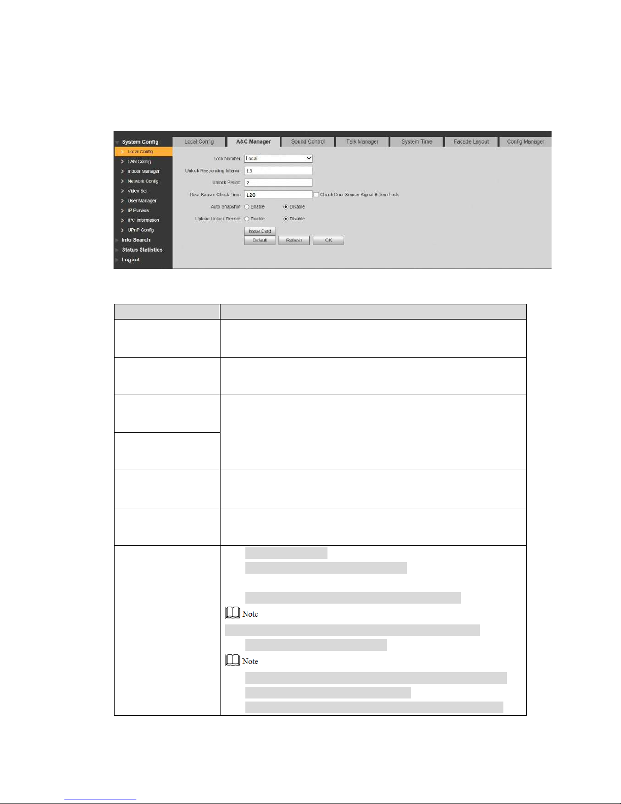
67
7.7.2
Access Manager
Set unlock responding interval, unlock period and door sens or check time.
Step 1
Step 2
Select “System Config >Local Config > A&C Manager”.
The system displays “A&C Manager” interface, as shown i n Fi gur e 7-28.
Figure 7-28
Set parameters and refer t o Table 7-8 for details.
Parameter
Description
Unlock Responding
Interval
After unlock, the interval t hat t he device responds to the next
unlock. The unit is “second” .
Unlock Period
After unlock, the period that it remains unlocked. The unit is
“second”.
Check Door Sensor
Signal Before Lock
Tick “Check Door Sensor Signal Before Lock” to enable the
function. If door sensor signal exists, it will not be locked. However,
after opening time exceeds the door sensor check time, give door
sensor alarm and report the alarm info to management centre
automatically.
Door Sensor Check
Time
Auto Snapshot
Tick “Enable”. 2 pictures will be snapshot automatically w hen t he
door is opened, and uploaded t o FT P or S D card.
Upload Unlock
Record
Reserved function.
Issue Card
Click “Issue Card”.
Swipe an unauthorized card at VUO.
The system pops up “Card I nfo” i nterface.
Enter “Roo m No. ” and “ C ard No.” and click “OK”.
Cards can be swiped continuously, within a period of 30s.
Click “OK” to finis h is suing card.
Click “OK” w ithin t he countdown, so the cards will be valid.
Otherwise, all card info wil l be invalid.
Click “Cancel” when issuing cards, in order t o st op issuing.
Step 3
Table 7-8
Click “OK” to save the settings.
Page 78
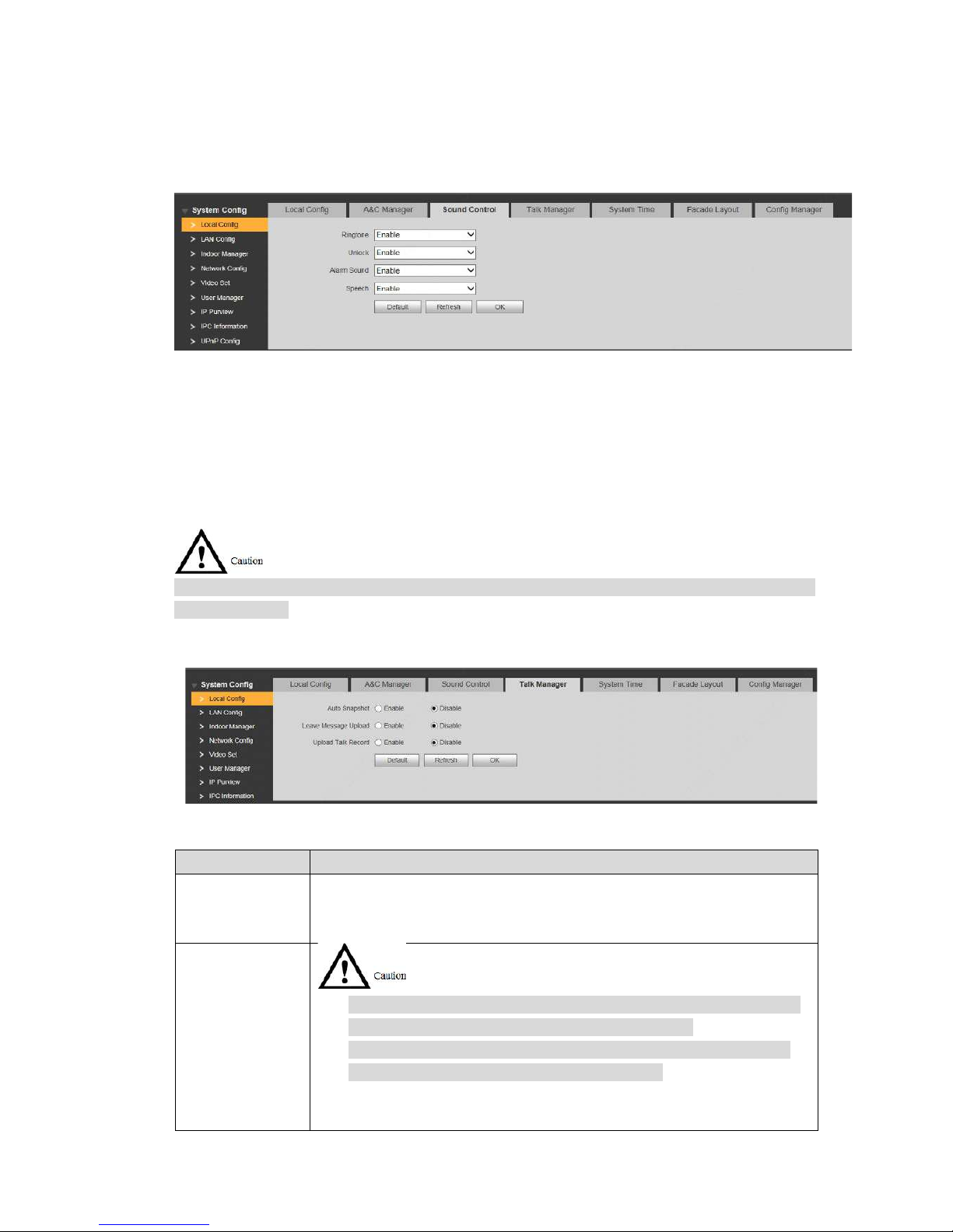
68
7.7.3
Sound Control
Enable and disable unlock sound, r ingtone, alarm sound and speech sound.
Step 1
Step 2
Step 3
Select “System Config >Local Config > Sound Control”.
The system displays “Sound Control” interface, as shown in Figure 7-29.
Figure 7-29
Enable or disable corresp onding sound.
Click “OK” to save the settings.
7.7.4
Talk Manager
Set auto snapshot, message and talk record.
Auto snapshot, message and r ecord are uploaded to FTP. Please confirm that FTP server has
been configured.
Step 1
Step 2
Select “System Config >Local Config > Talk Manager”.
The system displays “Talk Manager” i nt er f ace, as shown in Figure 7-30.
Figure 7-30
Set parameters and refer t o Table 7-8 for details.
Parameter
Description
Auto Snapshot
Tick “Enable”. 2 pictures will be snapshot automatically dur ing c alling,
and 1 picture will be snapshot aut omatically when pickup, and then
uploaded to FTP.
Leave Message
Upload
If VUH doesn’t have SD car d or SD card isn’t inserted, enable th is
function and set FTP server t o r ealize this function.
If VUH has SD card, the messages and records will be saved on
the VUH automatically. This f unct i on is invalid.
Tick “Enable” to enable the funct io n. VUH info interface has “Visitors’
Message” tab. When VUO calls VUH and gets no response, the system
Page 79
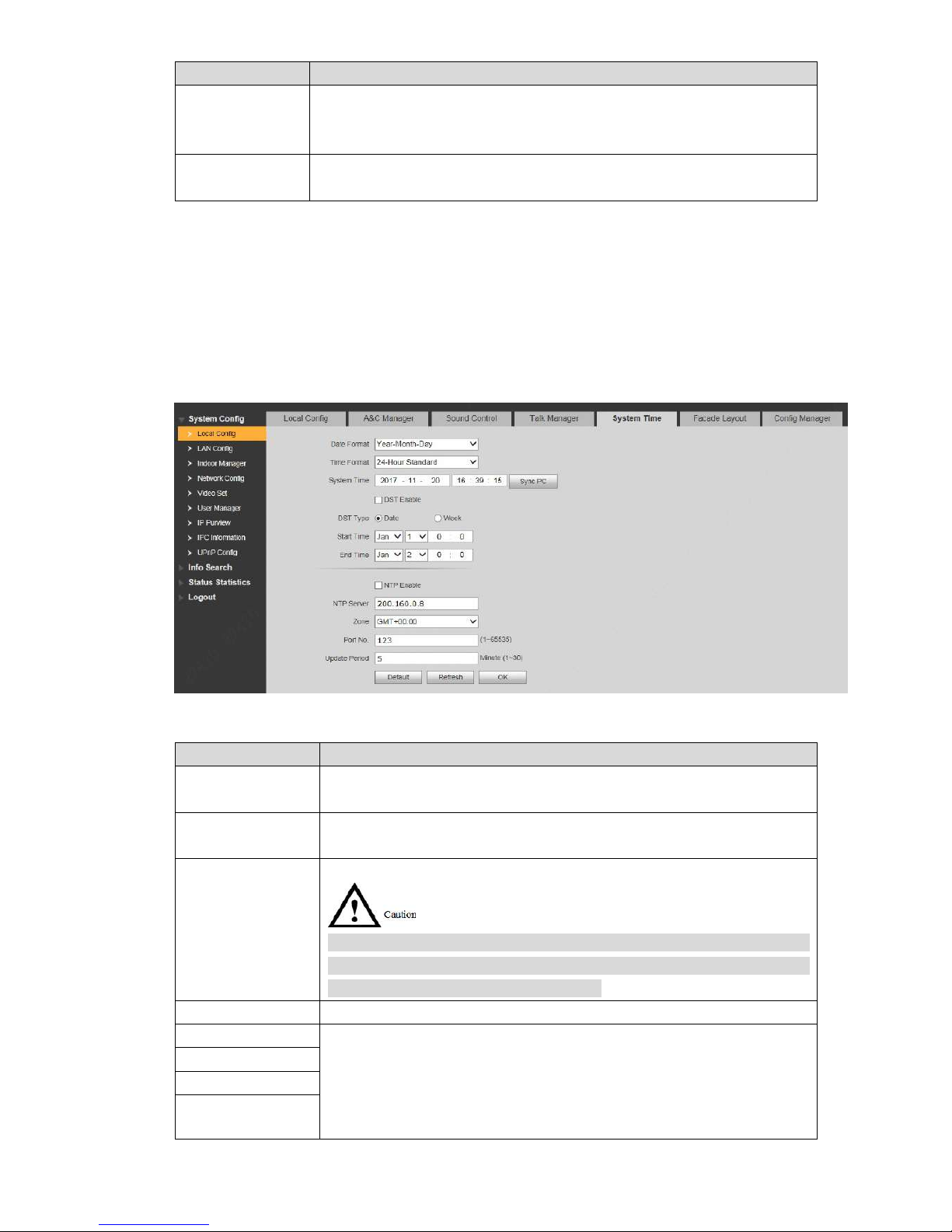
69
Parameter
Description
prompts that “No one answ er s. Please press 1 to leave a messag e”.
Press [1] to leave a picture/ me ssage. The system will uploa d t he
contents to FTP and mess ages ar e available at “Visitors’ Mess age” tab.
Upload Talk
Record
Reserved function.
Step 3
Table 7-9
Click “OK” to save the settings.
7.7.5
System Time
Set system date format, t ime format, system time and NTP ser ver.
Step 1
Step 2
Select “System Config >Local Config > System Time”.
The system displays “Sys t em Ti m e” interface, as shown in Figure 7-31.
Figure 7-31
Set parameters and refer t o Table 7-10 for details.
Parameter
Description
Date Format
Set date display format, includ ing Year-Month-Day, Mont h-Day-Year
and Day-Month-Year.
Time Format
Set time display format, includ ing 12-hour standard and 24-hour
standard.
System T ime
Set present system date and time of VUO.
System time shall not be changed arbitrarily; otherwise, it may fail to
inquire records and snapshots. Before changing system time, please
stop recording or disable auto snapshot.
Sync PC
Click “Sync PC”, so system ti me and local PC time are consistent .
DST Enable
Some countries or regions follow daylight-saving ti me ( DS T) . Choose
to enable DST or not according to actual needs:
1. Tick “DST Enable” to enable DST function.
2. Select “DST Type”, including “Date” and “Week”.
3. Set the start time and end time of DST.
DST Type
Start Time
End Time
Page 80
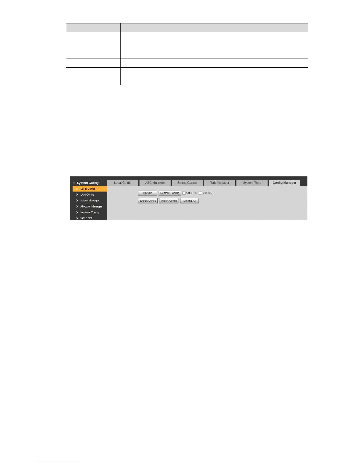
70
Parameter
Description
NTP Enable
Tick “NTP Enable” to enable this function.
NTP Server
Enter domain name or IP address of NTP server.
Zone
Select time zone of the dev ice.
Port No.
Set port no. of NTP server.
Update Period
The time interval of updating t i me between device and NTP server.
Maximum update period i s 30 m inutes.
Step 3
Table 7-10
Click “OK” to save the settings.
7.7.6
Config Manager
Realize backup or restore backup, VUH info, local config, networked c onfig and video config;
restore all default configur at ions.
Select “System Config >Local Config > Config Manager”. The system displays “Config Manager”
interface, as shown in Figur e 7-32.
Figure 7-32
Backup
Select “Card Info” or “VUH Info” (supp or t ing multiple choice), and click “Ba ckup”, so car
d
i
nfo and VUH info will make a backup in VUO.
Restore Backup
Click “Restore Backup”, s o car d in fo and VUH info is restored to backup info.
Export Config
Click “Export Config” to ex por t config info and save it at local device, so as t o restore confi
g
or
import into other devices.
Import Config
Click “Import Config” to im por t local config files to the device, so as t o r est or e data or
synchronize data.
Default All
Click “Default All”. After co nf irmation, the device will reboot, and res t ore all info to default
status, except IP address.
7.8
Indoor Manager
Manage VUH info and card info in the sy s t em.
Select “System Config > Indoor M anager”, and the system disp lay s “ Di gital Indoor Station
Manager” interface, as sh ow n in Figure 7-33.
Page 81
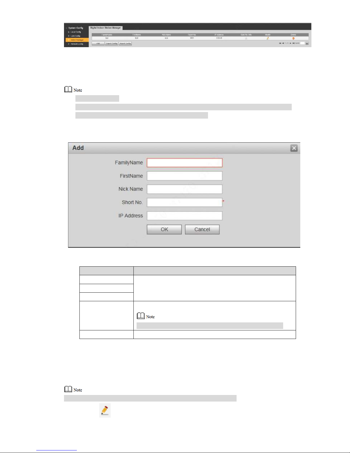
71
Figure 7-33
7.8.1
Add VUH
Add master VUH.
After “Network” interface of extension VUH has added and enabled master VUH, VUO
interface will obtain extension VUH info automatically.
Step 1
Step 2
Click “Add”.
The system displays “Add” int erface, as shown in Figure 7-34.
Figure 7-34
Set parameters and refer t o Table 7-11 for details.
Parameter
Description
Family Name
Set VUH user name and nick name, in order t o identify VUH.
First Name
Nick Name
VUH Short No.
Set VUH room no..
VUH short no. is the same as room no. configured at VUH.
IP Address
VUH IP address.
Step 3
Table 7-11
Click “OK” to save the settings.
7.8.2
Modify VUH
Only family name, first name and nick name of VUH can be modified.
Step 1 Click .
Page 82
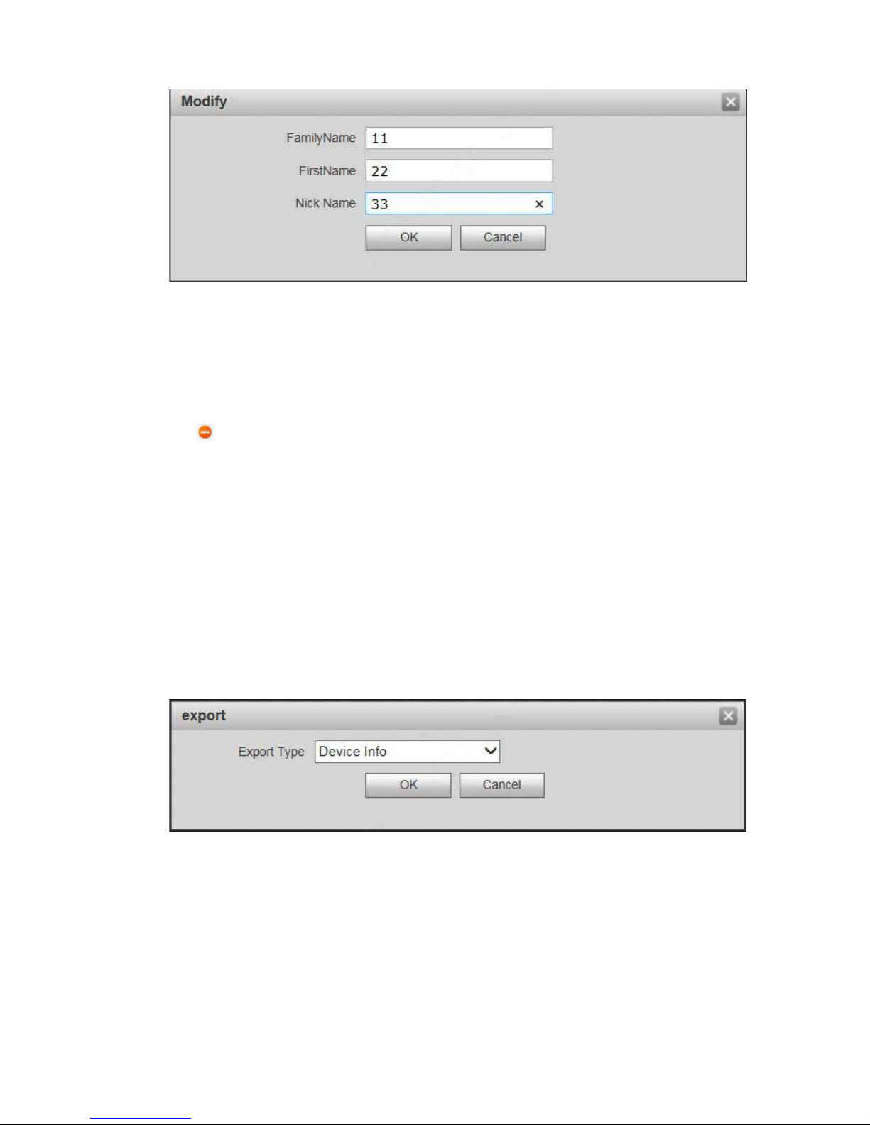
72
The system displays “Modify” interface, as shown in Figure 7-35.
Step 2
Step 3
Figure 7-35
Modify VUH “Family Name”, “Fi rst Name” and “Nick Name”.
Click “OK” to save the settings.
7.8.3
Delete VUH
Click to delete VUH info one by one.
7.8.4
Config Manager
Import or export device info, pas sw or d info, card no. info and login info of the device.
7.8.4.1 Export Config
Export and save config in the loc al device. When other devices nee d to configure the same
parameters, the config file can be i m ported.
Step 1
Step 2
Step 3
Step 4
Click “Export Config”.
The system displays “Expor t” interface, as shown in Figure 7-36.
Figure 7-36
Select “Export Type” and cli ck “OK”.
Select a location to save it.
Click “Save”.
The system prompts “Operation Succeeded”, representing successful export.
7.8.4.2 Import Config
Import local config file into t he device, so as to realize configuration.
Page 83
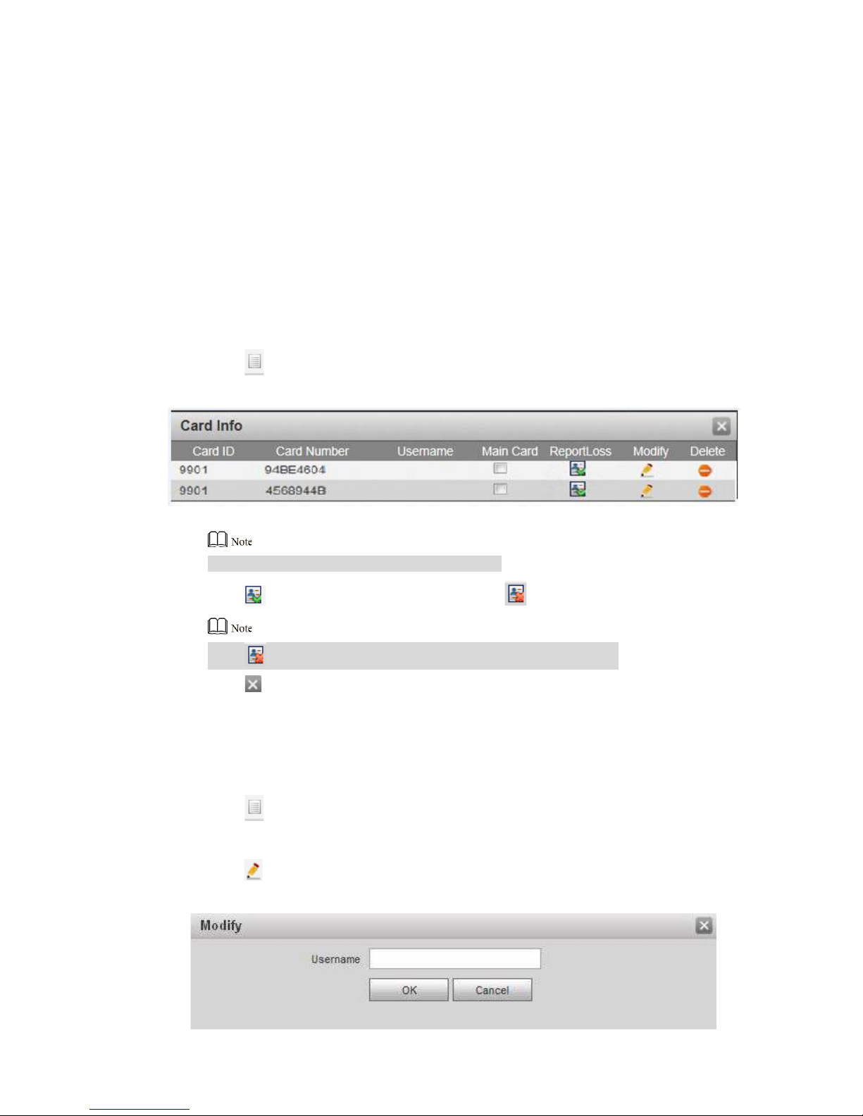
73
Step 1
Step 2
Click “Import Config”.
The system displays “Open” inter f ace.
Select config file (.log) to be i mp or ted and click “Open”.
The system prompts “Operation Succeeded”, representing successful import.
7.8.5
Card Manager
Report loss and cancel; modify card ID and delete card.
7.8.5.1 Report Loss
If a card is lost, please report loss, so the card is deprived of unlock authority temporarily, unt il
report of loss is cancelled.
Step 1
Step 2
Step 3
Click .
The system displays “Car d I nfo” i nterface, as shown in Figure 7-37.
F
igure 7-37
Villa VUO doesn’t support mother card function.
Click to repor t loss. The icon is switched to .
Click to close config interface.
7.8.5.2 Modify
Modify username of the car d.
Step 1
Step 2
Click .
The system displays “Car d I nfo” i nterface, as shown in Figure 7-37.
Click .
The system displays “Modify” interface, as shown in Figure 7-38.
Click t o canc el the report of loss, and recover unl ock function.
Page 84
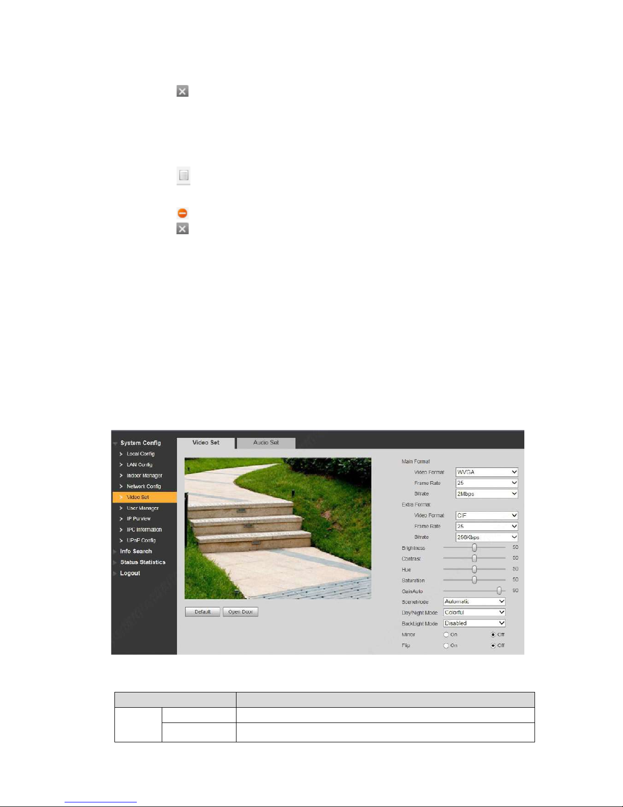
74
Step 3
Step 4
Modify the username.
Click “OK”.
Figure 7-38
Step 5 Click to close con fig interface.
7.8.5.3 Delete
After deletion, the card doesn’t ow n unlock authority.
Step 1
Step 2
Step 3
Click .
The system displays “Car d I nfo” i nterface, as shown in Figure 7-37.
Click to delete card info.
Click to close config interface.
7.9
Video Set
Set video picture and audio volume of VUO with camera.
7.9.1
Video Set
Step 1
Step 2
Select “System Config >Vi deo Set>Video Set”.
The system displays “Video Set” interface, as shown in Figure 7-39. Click “Open Door”,
and VUO is unlocked.
Figure 7-39
Set parameters and refer t o Table 7-12 for details.
Parameter
Description
Main
Format
Video Format Adjust resolution of video, including 720P, WVGA and D1.
Frame Rate Adjust transmiss ion speed, including 3, 25 and 30 fr am es.
Page 85
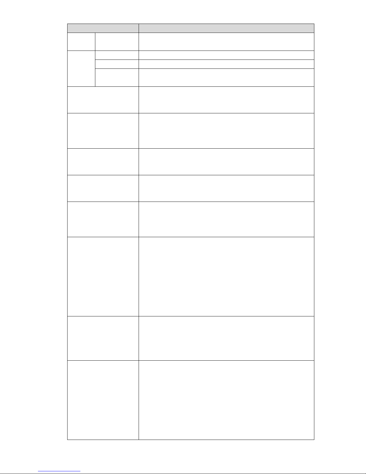
75
Parameter
Description
Bitrate
Select according to actual acces s network, including 256K bps,
512Kbps, 1Mbps, 2Mbps and 3M bps.
Extra
Format
Video Format
Adjust resolution of video, incl uding WVGA, D1, QVGA and CIF.
Frame Rate
Adjust transmission spee d, including 3, 25 and 30 frames.
Bitrate
Select according to actual acces s network, including 256K bps,
512Kbps, 1Mbps, 2Mbps and 3M bps.
Brightness
Adjust overall brightness i n a lin ear w ay. The larger the value is,
the brighter the image becomes; and vice versa. When this value
is large, the image dims easily.
Contrast
Adjust image contrast. The larger the value is, the more
contrasted the image becomes; and vice versa. When this value
is large, dark part of the image is t oo dark, while bright part
overexposes easily. When this value is small, the image d i ms.
Hue
Adjust image hue. There is a def ault value according to
sensitometric feature of th e sensor. Generally, it is unnecessary
to adjust this value greatly.
Saturation
Adjust image shade. The larger t he value is, the deeper the color
becomes, and vice versa. This value doesn’t affect overall
brightness of the image.
Gain Auto
Adjust image noise. The less the value is, the smaller the noise
becomes, but image brightness is very dark in dark scene. The
larger the value is, the more brightness will be obtained in dar k
scene, but image noise beco mes more obvious.
Scene Mode
Set white balance mode, main ly af fect i ng overall hue. It is
automatic mode by default.
Disabled: any mode is not set.
Automatic: set white balance automatically, compensate
white balance of different color temperature automatically,
and ensure normal image color.
Sunny: threshold value of white ba lance is set to sunny day
mode.
Night: threshold value of white ba lan c e is set to night mode.
Day/Night Mode
Camera image display is set to colorful or black and white mode.
Colorful: display colorful image.
Automatic: automatically c hoose to display colorful image or
black white image according to ambient brightness.
Black white: display black and whit e image.
Backlight Mode
There are several modes:
Disabled: no backlight.
Backlight: prevent silhouet te appearing in dark part of the
s
ubject against the light.
Wide dynamic: according to ambient brightness, the system
reduces brightness of high-
brightness area, increases
brightness of low-
brightness area, and thus displays both
areas clearly.
Inhibition: the system inhibits brightness of high-brightness
Page 86
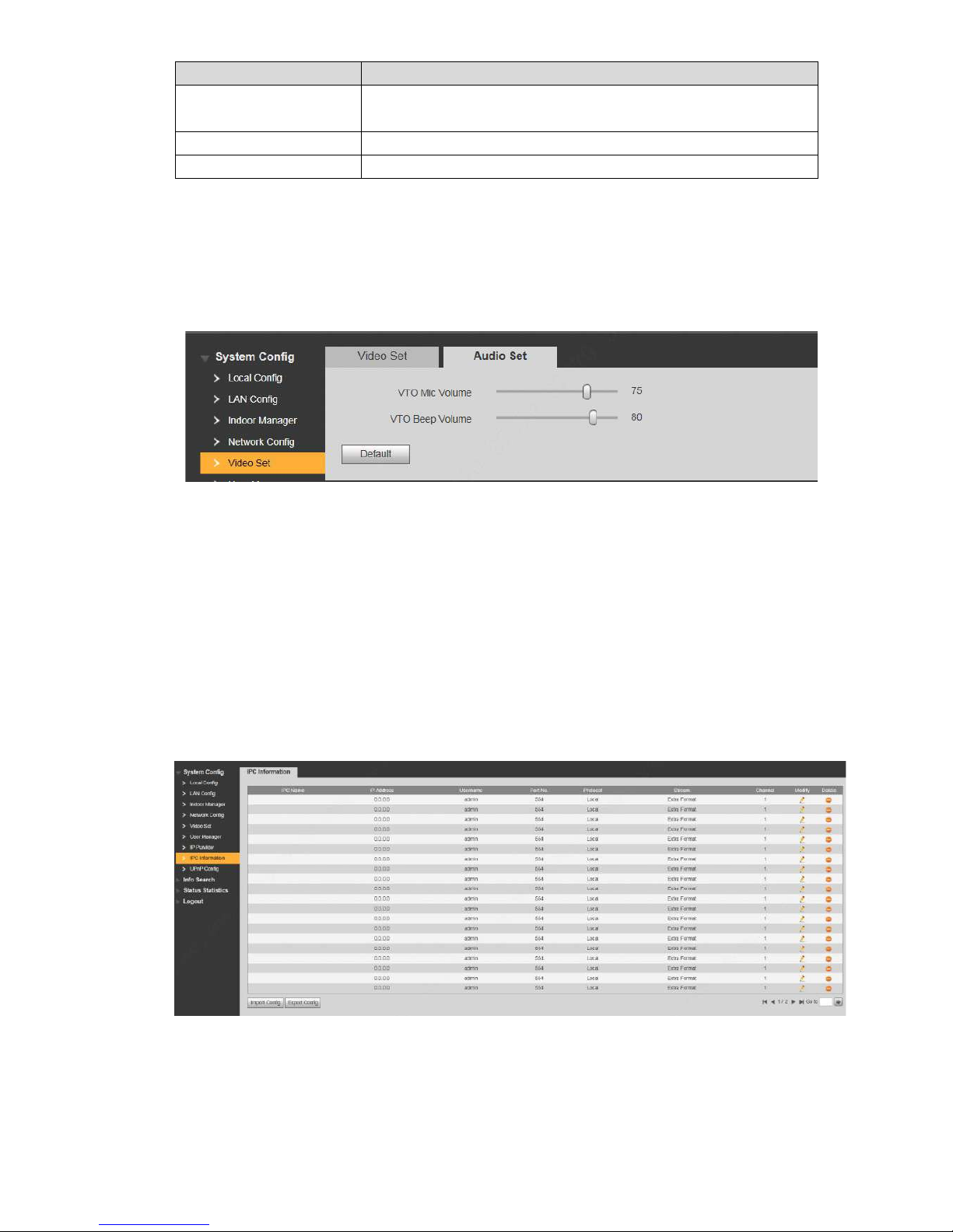
76
Parameter
Description
area of the image, reduces halo size and thus reduces
brightness of the entire image.
Mirror
Select “On”; the image will be t ur ned over from left to right.
Flip
Select “On”; the image will be t ur ned over from top to bottom.
Table 7-12
7.9.2
Audio Set
Step 1
Step 2
Select “System Config >Vi deo Set>Audio Set”.
The system displays “Audio Set” interface, as shown in Figure 7-40.
Figure 7-40
Adjust VUO mic volume and beep volume.
7.10
IPC Info
Add IP camera (IPC) info and su ppor t max. 32 channels. IPC info will be synchronized with VUH
automatically, in order to facilitate VUH monitoring.
Select “System Config > IPC In fo”. The system displays “IPC Info” int erface, as shown in Figure
7-41.
Figure 7-41
Page 87
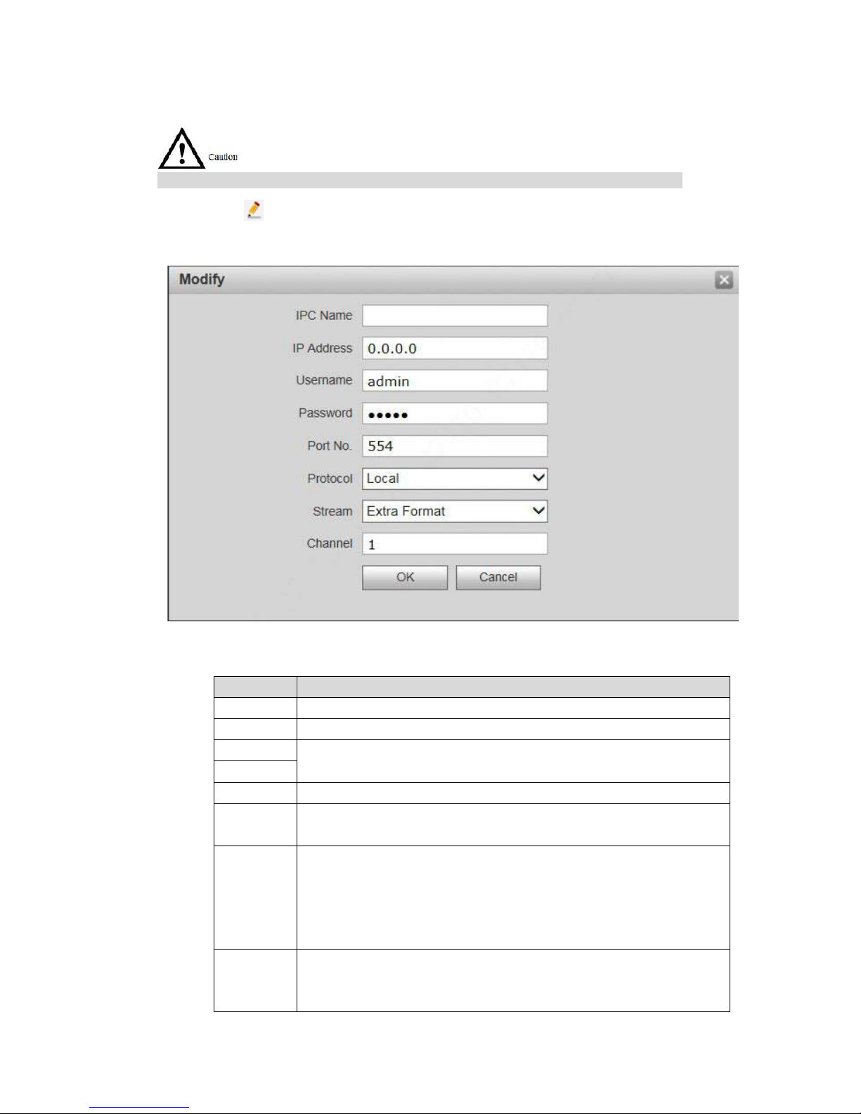
77
7.10.1
Add One IPC
Add IPC info one by one.
Add IPC directly, or add NVR/UVR/DVR devices to obtain info about the added IPC.
Step 1
Step 2
Click .
The system displays “Modify” interface, as shown in Figure 7-42.
Figure 7-42
Set parameters and refer t o Table 7-13 for details.
Parameter
Description
IPC Name Enter IPC/NVR/UVR/DVR name.
IP Address Enter IP address of the connected IPC/NVR/UVR/DVR.
Username
Enter the username and password to login WEB interface
of IPC/NVR/UVR/DVR.
Password
Port No. It is 554 by default.
Protocol
It consists of local protocol and Onvif protocol. Please sele ct
according to the protocol supp or t ed by the connected device.
Stream
Select from main format and ext r a f or m at according to needs.
Main format: large stream, high definition, large occupie d
bandwidth, suitable for local storage.
Extra format: smooth image, small occupied bandwidth, suitable
for low bandwidth network t r ansm ission.
Channel
To connect IPC, it is 1 by default.
To connect NVR/UVR/DVR, it is set to channel no. of IPC on
NVR/UVR/DVR.
Table 7-13
Page 88
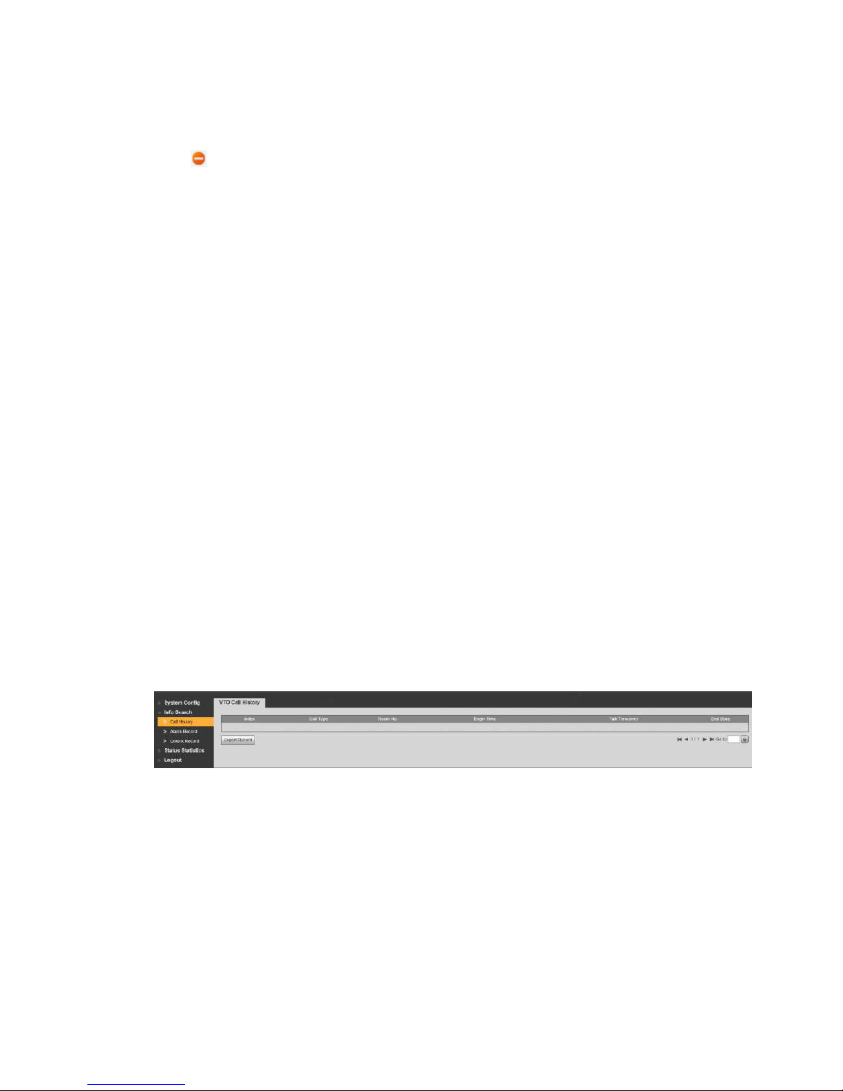
78
Step 3 Click “OK” to complete adding.
7.10.2
Delete
Click to delete camera info.
7.10.3
Batch Import
With batch import function, imp ort IPC info into the system.
Click “Import Config”, selec t conf ig f i le (. c sv) and import the file info into the system.
7.10.4
Batch Export
Export and save the present I PC info to the local device, for the sa ke o f fut ur e use.
Click “Export Config”; select the path to save config file.
7.11
Info Search
Search VUO call history, alarm record and unlock record.
7.11.1
Call History
View VUO call and talk record. Max . 1, 024 r ecords can be saved.
Select “Info Search> Call Hist or y”. The system displays “VUO Call History” interface, as shown in
Figure 7-43.
Click “Export Record” to export the VUO call record.
Figure 7-43
7.11.2
Alarm Record
View VUH 8-channel alarm, duress alarm and oth er alarm records. Max. 1,02 4 r ecor ds can be
saved.
Select “Info Search> Alar m Record”. The system displays “A larm Record” interface, as shown in
Figure 7-44. Click “Export Record” t o expor t t he VUO alarm record.
Page 89
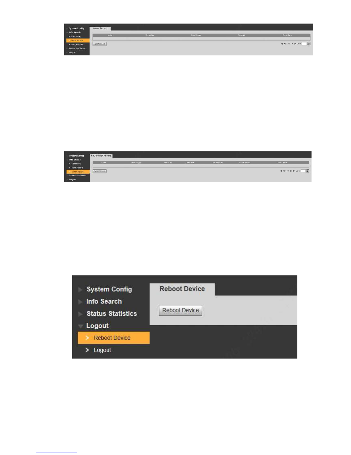
79
Figure 7-44
7.11.3
Unlock Record
View unlock records with car d, pass w ord, remote way and button. M ax. 1,000 records can be
saved.
Select “Info Search> Unlock Record> VUO Unlock Record”. The system displays “VUO Unlock
Record” interface, as show n in F igure 7-45.
Click “Export Record” to export the VUO unlock record.
Figure 7-45
7.12
Reboot Device
Reboot the device at WEB inter fac e.
Step 1
Step 2
Select “Logout > Reboot Devic e” .
The system displays “Reboot Device” interface, as shown in Fi gur e 7-46.
Click “Reboot Device”, so t he device reboots automatically.
WEB interface is switched t o WEB login interface.
Figure 7-46
7.13
Logout
Log out the WEB interface .
Page 90

80
Step 1
Step 2
Select “Logout > Logout”.
The system displays “Log out ” inter f ac e, as shown in Figure 7-47.
Click “Logout”.
Log out the WEB interface and r et ur n t o login interface.
Figure 7-47
Page 91
82
Appendix 1.1 VUO6210B
Model
VUO6210B
System
Main Processor
Embedded microcontroller
Operating System
Embedded LINUX operating system
Video
Video Compression Standard
H.264
Input/ Proximity Sensor
1.30 megapixel CMOS HD ca m er a
Night Vision
Support
Audio
Input
Omnidirectional micropho ne
Output
Built-in speaker
Talk Support two-way audio talk
Operating
Mode
Input Touch key (with backlight)
Swiping Car d Built-in IC card induct ion read head
Alarm
Tamper Alarm Support
Lock Status Detection Support
Network
Ethernet
10M/100Mbps self-adaptive
Network Protocol
TCP/IP
Specification
Power Supply
DC 10V–15V
Power Consumption
Standby ≤1W; working ≤10W
Working Temperature
﹣10℃~
+60
℃
Relative Humidity
10%RH~95%RH
Size (Length× Width × Hei ght )
114.2mm×43mm×154.2mm
Weight 0.5kg
Appendix 1.2 VUO600 0CM and VUO6100C
Model
VUO6000CM and VUO6100C
System
Main Processor Embedded microcontroller
Operating System Embedded LINUX Operati ng System
Video
Video Compression Standard H.264
Input/ Proximity Sensor 1.30 megapixel CMOS HD camera
Night Vision
Support
Audio
Input
Omnidirectional micropho ne
Output
Built-in speaker
Talk
Support two-way audio talk
Operating
Mode
Input
Input with single key (with backlight)
Swiping Car d
Only VUO6100C supports
Alarm
Tamper Alarm
Support
Appendix 1 Technical Parameters
Page 92
83
Lock Status Detection
Support
Network
Ethernet
10M/100Mbps self-adaptive
Network Protocol
TCP/IP
Power Supply
DC 10V–15V
Power Consumption
Standby≤1W; working≤10W
Working Temperature
﹣10℃~+60℃
Relative Humidity
10%RH~95%RH
Size (Length× Width × Hei ght )
100mm×42mm×141mm
Weight
0.5kg
Appendix 1.3 VUO2000A
Model
VUO2000A
System
Main Processor Embedded microcontroller
Operating System Embedded LINUX Operati ng System
Video
Video Compression Standard H.264
Input/ Proximity Sensor 1 megapixel CMOS HD camera
Night Vision
Support
Audio
Input
Omnidirectional micropho ne
Output
Built-in speaker
Talk
Support two-way audio talk
Operating
Mode
Input
Input with single key
Lock Status Detection
Support (optional)
Network
Ethernet
10M/100Mbps self-adaptive
Network Protocol
TCP/IP
Specification
Power Supply
DC 10V–15V
Power Consumption
Standby≤1W; working≤10W
Working Temperature
﹣30℃~+70℃
Relative Humidity
10%RH~90%RH
Size (Length× Width × Hei ght ) 129.9mm×32.2mm×140mm
Weight 0.8kg
Appendix 1.4 VUO2000A-2
Model
VUO2000A-2
System
Main Processor
Embedded microcontroller
Operating System
Embedded LINUX Operati ng System
Video
Video Compression Standard
H.264
Input/ Proximity Sensor
1 megapixel CMOS HD camera
Night Vision
Support
Audio
Input
Omnidirectional micropho ne
Output
Built-in speaker
Talk
Support two-way audio talk
Operating
Input
Input with single key
Page 93

84
Mode
Lock Status Detection
Support (optional)
Network
Ethernet
10M/100Mbps self-adaptive
Network Protocol
TCP/IP
Specification
Power Supply
DC 24V
Power Consumption
Standby ≤1W; working≤7W
Working Temperature
﹣30℃~+60℃
Relative Humidity
10%RH~90%RH
Size (Length× Width × Hei ght )
129.9mm×32.2mm×140mm
Weight
0.8kg
Page 94
85
Appendix 2.1 Specification of Network Cable
Please try to ensure that wiring len gt h LN doesn’t exceed 100m.
Please select network cable reasonably according to wiring lengt h LN between VUO and VUH.
Specification of Network Cable
0<LN≤50m
50<LN≤100m
UTP Cat5e/Cat6: 10 Ohm/ 100m
Yes
Yes
UTP Cat5e/Cat6: 18.8 Ohm/100m
Yes
No
Appendix 2.2 Specification of Extensio n P ower Cord
Before power on, please chec k whet her positive and negative poles of extension power cord
are wired correctly; av oid reverse connection.
Please select suitable extension power cord accordi ng to distance LC between adapter and
VUO.
Specification of Extension Power Cor d
0<LC≤30m
30<LC≤100m
20AWG
Yes
No
18AWG
Yes
Yes
17AWG
Yes
Yes
Appendix 2.3 Specification of Embedded B ox
Model
Specification of Embedded Box
VUO6000C, VUO6100C, VUO6000CM
86 box
VUO6110B, VUO6210B, VUO6110BW
86 box, 120 box
VUO2000A
Flush mounting box 126mm×115mm
VUO2000A-2
Flush mounting box 126 mm×115mm
Appendix 2 Accessory Specification
 Loading...