


Video Intercom | User Manual - Digital

II
Mandatory actions to be taken towards cybersecur i ty
Cybersecurity Recommendation s
1. Change Passwords and Use Strong Passwords:
The number one reason systems get “hacked” is due to having weak or default passwords. It is
recommended to change default passwords immediately and choose a strong password
whenever possible. A strong password should be made up of at least 8 characters and a
combination of special char acters, numbers, and upper and lower case letters.
2. Update Firmware
As is standard procedure in the tech-industry, we recommend keeping NVR, DVR, and IP
camera firmware up-to-date to ensure the system is current with the latest security patches and
fixes.
“Nice to have” recommendati ons t o improve your ne twork security
1. Change Passwords Regularly
Regularly change the credentials to your devices to help ensure that only authorized users are
able to access the system.
2. Change Default HTTP and TCP Ports:
● Change default HTTP and TCP ports for systems. These are the two ports used to
communicate and to view video feeds remotely.
● These ports can be changed t o any set of numbers between 1025-65535. Avoiding the
default ports reduces the risk of outsiders being able to guess w hi ch por t s you are using.
3. Enable HTTPS/SSL:
Set up an SSL Certificate to enable HTTPS. This will encrypt all communication between your
devices and recorder.
4. Enable IP Filter:
Enabling your IP filter will prevent everyone, except those w ith s pecified IP addresses, from
accessing the system.
5. Change ONVIF Password:
On older IP Camera firmware, the ONVIF password does not change when you change the
system’s credentials. You will need to either update the camera’s firmware to the latest revision
or manually change the ONVIF password.
6. Forward Only Ports You Need:

III
● Only forward the HTTP and TCP ports that you need to use. Do not forward a huge range of
numbers to the device. Do not DMZ the device's IP address.
● You do not need to forward any ports for individual cameras if they are all connected to a
recorder on site; just the NVR is needed.
7. Disable Auto-Login on STORM VMS:
Those using STORM VMS to view their system and on a computer that is used by multiple
people should disable auto-login. This adds a layer of security to prevent users without the
appropriate credentia ls fro m ac c essing the system.
8. Use a Different Username and Password for ST ORM VMS:
In the event that your social media, bank, email, etc. account is compromised, you would not
want someone collecting those passwords and trying them out on your video surveillance
system. Using a different username and password for your security system will make it more
difficult for someone to gu ess t heir way into your system.
9. Limit Features of Gue st Accounts:
If your system is set up for multiple users, ensure that each user only has rights to features and
functions they need to use t o per form their job.
10. UPnP:
● UPnP will automatically try to forward ports in your router or modem. Normally this would be a
good thing. However, if your system automatically forwards the ports and you leave the
credentials defaulted, y ou may end up with unwanted visitors.
● If you manually forwarded the HTTP and TCP ports in your router/modem, this feature should
be turned off regardless. Disabling UPnP is recommended when the function is not used in real
applications.
11. SNMP:
Disable SNMP if you are not using it. If you are using SNMP, you should do so only temporarily,
for tracing and testing pur poses only.
12. Multicast:
Multicast is used to share video streams between two recorders. Currently there are no known
issues involving Multicast, but if you are not using this feature, deactivation can enhance your
network security.
13. Check the Log:
If you suspect that someone has gained unauthorized access to your system, you can check
the system log. The system log will show you which IP addresses were used to login to your
system and what was accessed.
14. Physically Lock Do wn t he Device:

IV
Ideally, you want to prevent any unauthorized physical access to your syst em. The best w ay t o
achieve this is to install the recorder in a lockbox, locking server rack, or in a room that is
behind a lock and key.
15. Connect IP Cameras t o the PoE Ports on the Back of an NVR:
Cameras connected to the PoE ports on the back of an NVR are isolated from the outside world
and cannot be accessed directly.
16. Isolate NVR and IP Camera Network
The network your NVR and IP camera resides on should not be the same network as your
public computer network. This will prevent any visitors or unwanted guests from getting access
to the same network the security system needs in order to function properly.
V
General
Type
Model Series
Specific Model
VUH5241 series
VUH5241DW
Type A
VUH1520A, VUH1520AS-H, VUH1520AH, VUH1520AS
Type B
VUH1550B, VUH1560B(W)
Type CH
VUH1510CH, VUH1520CH, VUH1550CH, VUH1550CHM
VUH16 series
VUH1660CH
VUH2X series
VUH2221A
2-wire VUH
VUH1550CHW-2, VUH5222CH
Signal Words
Meaning
This document mainly introduces function, structure, network, installation process,
debugging process of VUH products matched with Version 4.0 VU UI interface, together
with operating instruction and technical parameter of UI interface.
Models
Foreword
VUH5221 series VUH5221DW, VUH5221D, VUH5221DW-C, VUH5221D-C
Digital
VUH
VUH15
series
Device Upgrade
Please don’t cut off power supply during upgrade. Power can be cut only after the device
completes upgrade and re boot s.
Safety Instructions
The following categoriz ed sign al w or ds with defined meaning might appear in the Manual.
Indicates a high potential hazard which, if not avoided, will result
in death or serious injury.
Indicates a medium or low potential hazard which, if not avoided,
could result in slight or mo der at e in jur y.
Indicates a potential risk which, if not avoided, could result i n
property damage, data los s, low er performance, or unpredictable
result.
Provides methods to help you solve a problem or save y ou t ime.
Provides additional information as the emphasis and suppl ement
to the text.

VI
Revision History
No.
Version
Revision Content
Release Date
1
V1.0.0
First release
2017.11.1
2
V1.0.1
Add privacy protection not ice
2018.05.23
Privacy Protection Notice
As the device user or data controller, you might collect personal data of others' such as face,
fingerprints, car plate number, Email address, phone number, GPS and so on. You need to be
in compliance with the local privacy protection laws and regulations to protect the legitimate
rights and interests of other people by implementing measures include but not limited to:
providing clear and visible identification to inform data subject the existence of surveillance
area and providing related cont ac t .
About the Manual
The Manual is for reference only. If there is inconsistency between the Manual and the
actual product, the actual pr oduct shall prevail.
We are not liable for any loss caused by the operations that do not comply with the Manual.
The Manual would be updated according to the latest laws and regulations of related
regions. For detailed information, see the paper User's Manual, CD-ROM, QR code or our
official website. If there is inconsistency between paper User's Manual and the electronic
version, the electronic v er sion shall prevail.
All the designs and software are subject to change without prior written notice. The product
updates might cause some differences between the actual product and the Manual. Please
contact the customer serv ice for the latest program and supplementary documentation.
There still might be deviation in technical data, functions and operations description, or
errors in print. If there is any doubt or dispute, please refer to our fin al explanation.
Upgrade the reader software or try other mainstream reader software if the Guide (in PDF
format) cannot be opened.
All trademarks, registered trademarks and the company names in the Manual are the
properties of their respecti ve owners.
Please visit our website, contact the supplier or customer service if there is any problem
occurred when using the device.
If there is any uncertainty or c ont r oversy, please refer to our final explanation.

VII
Important Safeguards and Warnings
The following description is the correct application method of the device. Please read the
manual carefully before use, in order to prevent danger and property loss. Strictly conform to
the manual during application and keep it properly after r eading.
Operating Requirement
Please modify the default pas sw or d after deployment, to avoid being stolen.
Please don’t place and inst all the device in an area exposed to direct sunlight or near heat
generating device.
Please don’t install the de vice in a humid, dusty or fuliginous area.
Please keep its horizonta l inst allation, or install it at stable p lac es, and prevent it from
falling.
Please don’t drip or splash liqui ds onto the device; don’t put on the dev ice anything filled
w
ith liquids, in order to prevent liquids from flowing into the device.
Please install the device at well-ventilated places; don’t block its ventilation opening.
Use the device only within r at ed input and output range.
Please don’t dismantle the device arbitrarily.
Power Requirement
The product shall use electric wires (power wires) recommended by this area, which shal l
be used within its rated specification.
Please use power supply that meets SELV (safety extra low voltage) requirements, and
supply power with rated voltage that conforms to Limited Power Source in IEC60950-1. For
specific power supply requirements, please refer to device labels.
If power plug or appliance c oupl er is a disconnecting device, during normal use, please
k
eep an angle that facilitates operation.

VIII
Table of Contents
Cybersecurity Recommendations ........................................................................................................ II
Foreword ................................................................................................................................................. V
Important Safeguards and Warnings ................................................................................................ VII
1 Product Overview ................................................................................................................................ 1
1.1 Product Profile ................................................................................................................................ 1
1.2 Product Function ............................................................................................................................ 1
2 Product Structure ................................................................................................................................ 3
2.1 Front Panel ..................................................................................................................................... 3
2.1.1 VUH5221 Series /VUH5241 Series ..................................................................................... 3
2.1.2 VUH15 Series Type A/B ....................................................................................................... 4
2.1.3 VUH15 Series Type CH/5222CH ......................................................................................... 6
2.1.4 VUH1660CH ........................................................................................................................ 7
2.1.5 VUH2221A ........................................................................................................................... 7
2.2 Rear Panel Port .............................................................................................................................. 9
2.2.1 VUH5221 Series/VUH5241 Series ...................................................................................... 9
2.2.2 VUH15 Series Type A/ Type B/ Type CH ............................................................................. 9
2.2.3 VUH5222CH ...................................................................................................................... 10
2.2.4 VUH1660CH ...................................................................................................................... 10
2.2.5 VUH2221A .........................................................................................................................
3 Network Diagram ............................................................................................................................... 12
3.1 2-wire System ............................................................................................................................... 12
3.2 Digital System ............................................................................................................................... 13
4 Device Installation ................................................................................................................................ 15
4.1 Installation Flow Chart .................................................................................................................. 15
4.2 Open-case Inspection ................................................................................................................... 15
4.3 Installation Requirement ............................................................................................................... 16
4.4 Device Installation ........................................................................................................................ 16
4.4.1 Surface Installation ............................................................................................................ 16
4.4.2 Installation with 86 Box ...................................................................................................... 17
5 Device Debugging .............................................................................................................................. 18
5.1 Debugging Settings ...................................................................................................................... 18
5.1.1 VUO Settings ..................................................................................................................... 18
5.1.2 VUH Config ........................................................................................................................ 23
5.2 Debugging Verification ................................................................................................................. 28
5.2.1 VUO Calls VUH.................................................................................................................. 28
5.2.2 VUH Monitors VUO ............................................................................................................ 28
6 Interface Operation ............................................................................................................................ 30
6.1 Main Interface
6.2 Setting ........................................................................................................................................... 31
6.2.1 Ring Settings ..................................................................................................................... 31
6.2.2 DND Settings ..................................................................................................................... 35
............................................................................................................................... 30
10
6.2.3 Alarm Setting...................................................................................................................... 36
6.2.4 Mode Setting ...................................................................................................................... 40

IX
6.2.5 General Setting .................................................................................................................. 41
6.2.6 Product Info........................................................................................................................ 47
6.3 Project Settings ............................................................................................................................ 48
6.3.1 Forget Password ................................................................................................................ 48
6.3.2 Network Settings ................................................................................................................ 49
6.3.3 VUH Config ........................................................................................................................ 52
6.3.4 VUO Config ........................................................................................................................ 53
6.3.5 Search Device ................................................................................................................... 53
6.3.6 Default ................................................................................................................................ 56
6.3.7 Reset MSG ........................................................................................................................ 56
6.4 Call ................................................................................................................................................ 57
6.4.1 Contact ............................................................................................................................... 57
6.4.2 Call User ............................................................................................................................ 58
6.4.3 Call from User .................................................................................................................... 61
6.4.4 Call from VUO .................................................................................................................... 62
6.4.5 Call Log .............................................................................................................................. 63
6.5 Monitor .......................................................................................................................................... 64
6.5.1 Monitoring of VUO ............................................................................................................. 64
6.5.2 Monitoring of IPC ............................................................................................................... 66
6.5.3 Favorite
6.6 SOS .............................................................................................................................................. 69
6.7 Info ................................................................................................................................................ 70
6.7.1 Alarm .................................................................................................................................. 70
6.7.2 Guest Message .................................................................................................................. 71
6.7.3 Publish Info ........................................................................................................................ 72
6.7.4 Video Pic ............................................................................................................................ 73
6.8 Unlock Function ............................................................................................................................ 73
6.9 Arm and Disarm Function ............................................................................................................. 73
6.9.1 Arm ..................................................................................................................................... 73
6.9.2 Disarm ................................................................................................................................ 74
Appendix 1 Technical Parameters ........................................................................................................................ 76
Appendix 1.1 VUH5221D Series /VUH5241DW Series .................................................................... 76
Appendix 1.2 VUH5222CH Series ..................................................................................................... 76
Appendix 1.3 VUH15 Series Type A/B/CH ......................................................................................... 77
Appendix 1.4 VUH16 Series .............................................................................................................. 78
Appendix 1.5 VUH2221A Series ........................................................................................................ 78
.............................................................................................................................. 69

1
1 Product Overview
1.1
Product Profile
VUH series product is a digital video intercom home station for numerous homes, integrating
monitoring, intercom and unlocking. With embedded technology, all IP network, SNMP (Simple
Network Management Protocol) network management technology and network encryption
technology, achieve more stable system operation, richer functional extension, more
convenient system management and safer data transmission.
1.2
Product Function
Wi-Fi Networking
Realize Wi-Fi networking of devices.
Video Intercom
Call or connect VUO and VUH; realize talk.
Monitoring
Monitor fence station, VUO and IPC devices.
SOS
Press the key to call the Call Center in case of an emergency .
Auto Snapshot
Snapshot the call picture or mo nit oring picture, and store them in SD c ar d or FTP.
DND (Do Not Disturb)
Avoid other’s incoming cal l interference.
Remote Unlock
Realize remote unlock.

2
Arm and Disarm
Provide 6/8-channel area setting, arm and disarm them.
Playback
Play back videos and pict ur es in SD card of this device.
Alarm
After 8/6-channel area triggers an alarm, pop up an alarm prompt interface, pr ovide linkage
alarm output and report to Cal l Center.
Record Inquiry
Inquire call records and alar m records.
Message Inquiry
Inquire guests’ message, videos, pictures and anno uncements issued by Property
Management Center.
3
2 Product Structure
No.
Name
Description
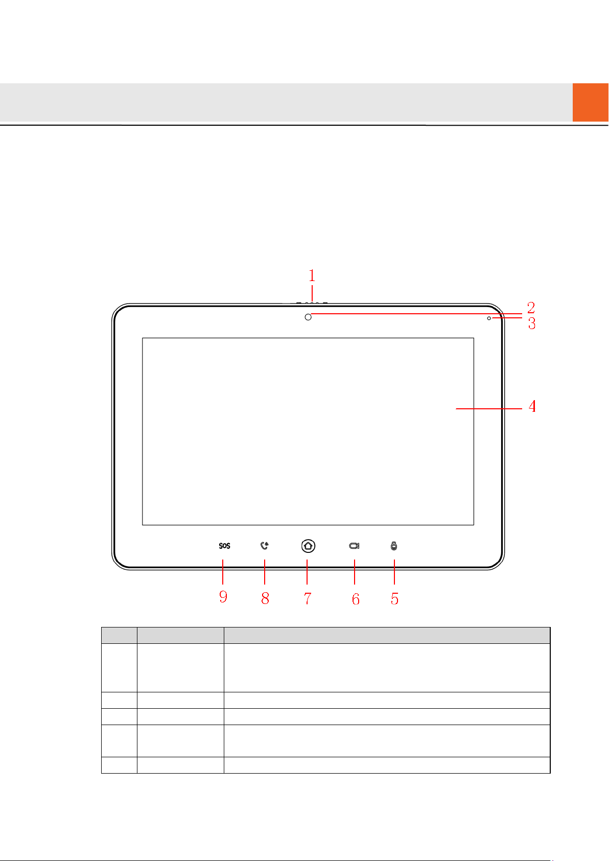
2
Camera
Only VUH5221DW-C supports front-facing c amera.
3
Microphone
Voice input.
4
7″ type D digital VUH owns a 7″ high-definition LCD.
2.1
Front Panel
2.1.1
VUH5221 Series /VUH5241 Series
VUH5221D is a 7″ digital indoor monitor. Their front panels have the same size, as shown in
Figure 2-1. Please refer to Tabl e 2-1 for details.
1 Camera
occlusion
switch
Display screen
5 Unlock Press this key during calli ng, talking, monitoring and speakin g of
Slide it to occlude or open t he cam er a.
10″ type D digital VUH owns a 10″ high-definition LCD.
Figure 2-1
4
No.
Name
Description
VUO, so corresponding VUO will be unlocked.
6
Monitor
In standby mode, press this key to monitor the main VUO.
7
Menu
Press this key to return to ma in me nu.
8
In case of incoming call, press this key to answer the call.
9
SOS
Press this key to call the Call Center in case of emergency.
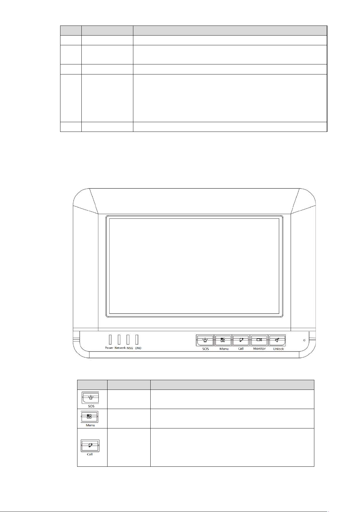
Icon
Name
Description
Press this key to call the Call Center in case of
Call
During monitoring, press t his key to exit monitoring.
During talk, press this key to hang up.
During monitoring, press t his key to speak to unit VUO, villa
VUO and fence station.
During speaking, press thi s key to exit speaking.
Table 2-1
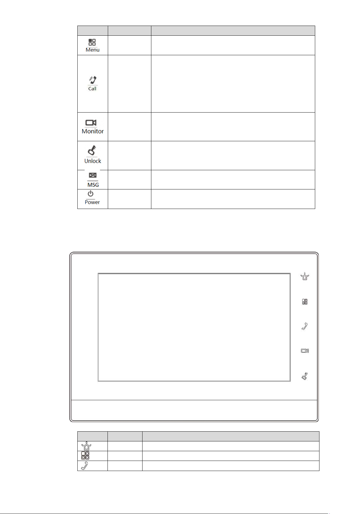
2.1.2
VUH15 Series Type A/B
In VUH15 series, different types of dev ices have different front panels.
Figure 2-2 VUH15 Series Type A
SOS
Menu Press this key to return to ma in me nu.
Call
emergency.
In case of incoming call, press this key to answer
During talk, press this key to hang up.
During monitoring, press t his key to speak to
the call.
5
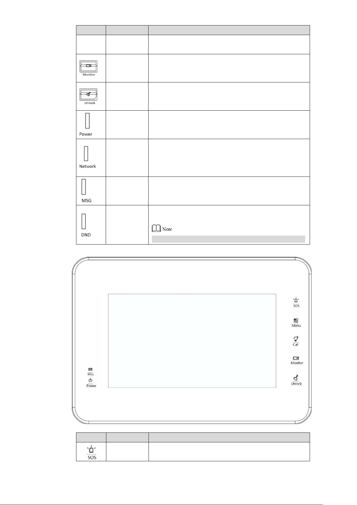
Icon
Name
Description
apartment VUO, villa VUO and fence station.
In standby mode, press this key to monitor the
Press this key during calli ng, talking, monitoring and
If this indicator turns on, it r epr esents normal
If this indicator turns on in gr een, it r epresents that DND
Icon
Name
Description
Monitor
During speaking, press thi s key to exit speaking.
main VUO.
During monitoring, press t his key to exit monitoring.
Unlock
Power
indicator
Network
indicator
Message
indicator
DND
indicator
speaking of VUO, so corresponding VUO will be
unlocked.
If this indicator turns on in gr een, it r epresents normal
power supply.
communication with VUO.
If this indicator turns off, it repr es ents abnormal
communication with VUO.
If this indicator turns on, it r epr esents that there are
unread messages.
function is enabled.
For DND settings, please r efer t o “6.2.2 DND Settings”.
Table 2-2
Figure 2-3 VUH15 Series Type B
SOS
Press this key to call the Call Center in case of
emergency.
6
Icon
Name
Description
Menu Press this key to return to main me nu.
In case of incoming call, press this key to answer
In standby mode, press this key to monitor the
Press this key during calli ng, talking, monitoring and
Message
If this indicator turns on, it r epr esents that there are
Power
If this indicator turns on in gr een, it r epresents normal
Icon
Name
Description
SOS
Press this key to call the Call Center in case of emergency.
Menu
Press this key to return to ma in me nu.
the call.
Call
During talk, press this key to hang up.
During monitoring, press t his key to speak to
apartment VUO, villa VUO and fence station.
During speaking, press thi s key to exit speaking.
Monitor
main VUO.
During monitoring, press t his key to exit monitoring.
Unlock
indicator
indicator
speaking of VUO, so corresponding VUO will be
unlocked.
unread messages.
power supply.
Table 2-3
2.1.3
VUH15 Series Type CH/5222CH
Call In case of incoming call, press this key to answer the
Figure 2-4
7
Icon
Name
Description
call.
During talk, press this key to hang up.
In standby mode, press this key to monitor the main
Press this key during calli ng, talking, monitoring and
No.
Name
Description
If this indicator turns on in gr een, it r epresents
During monitoring, press t his key to speak to apartment
VUO, villa VUO and fence station.
During speaking, press thi s key to exit speaking.
Monitor
VUO.
During monitoring, press t his key to exit monitoring.
Unlock
speaking of VUO, so corresponding VUO will be unlocked.
Table 2-4
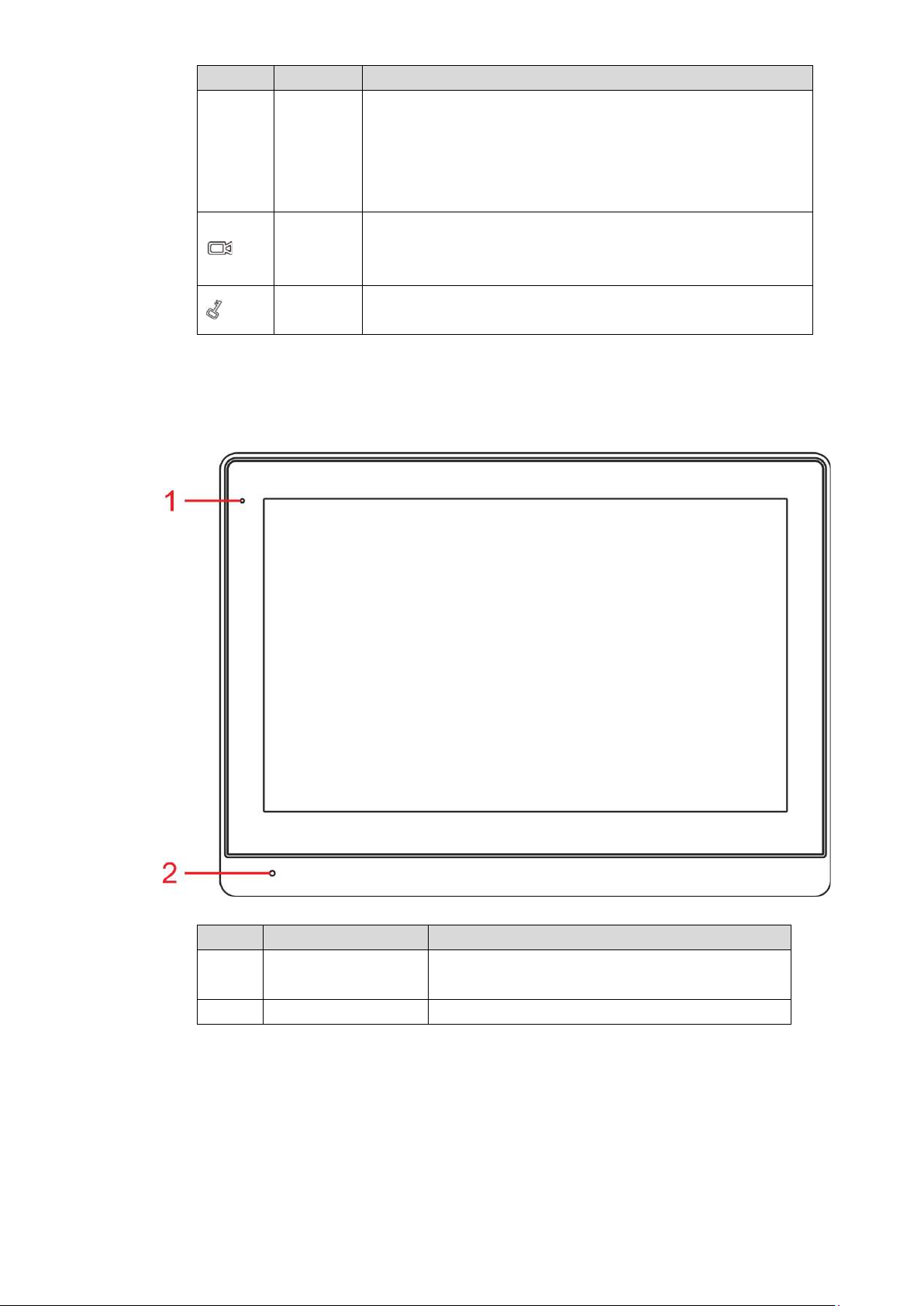
2.1.4
VUH1660CH
1 Power indicator
2 Microphone Audio input.
2.1.5
VUH2221A
Figure 2-5
normal power supply.
Table 2-5
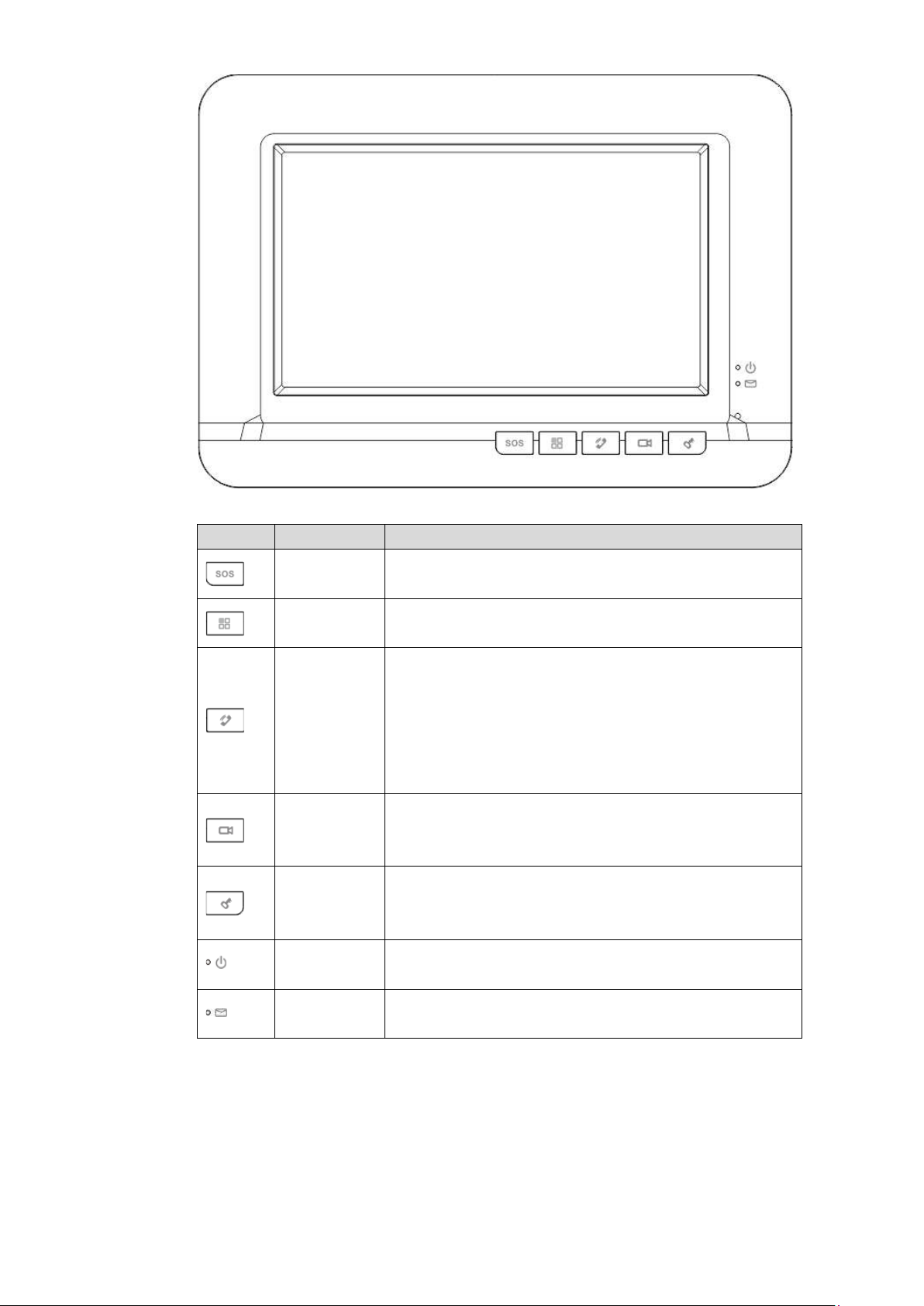
8
Icon
Name
Description
Press this key to call the Call Center in case of
Press this key during calli ng, talking, monitoring and
Power
If this indicator turns on in gr een, it r epresents normal
Message
If this indicator turns on, it r epr esents that there are
Figure 2-6
SOS
Menu Press this key to return to main me nu.
emergency.
In case of incoming call, press this key to answer
the call.
Call
During talk, press this key to hang up.
During monitoring, press t his key to speak to
apartment VUO, villa VUO and fence station.
During speaking, press thi s key to exit speaking.
In standby mode, press this key to monitor the
Monitor
main VUO.
During monitoring, press t his key to exit monitoring.
Unlock
indicator
indicator
speaking of VUO, so corresponding VUO will be
unlocked.
power supply.
unread messages.
Table 2-6
9
2.2
Rear Panel Port
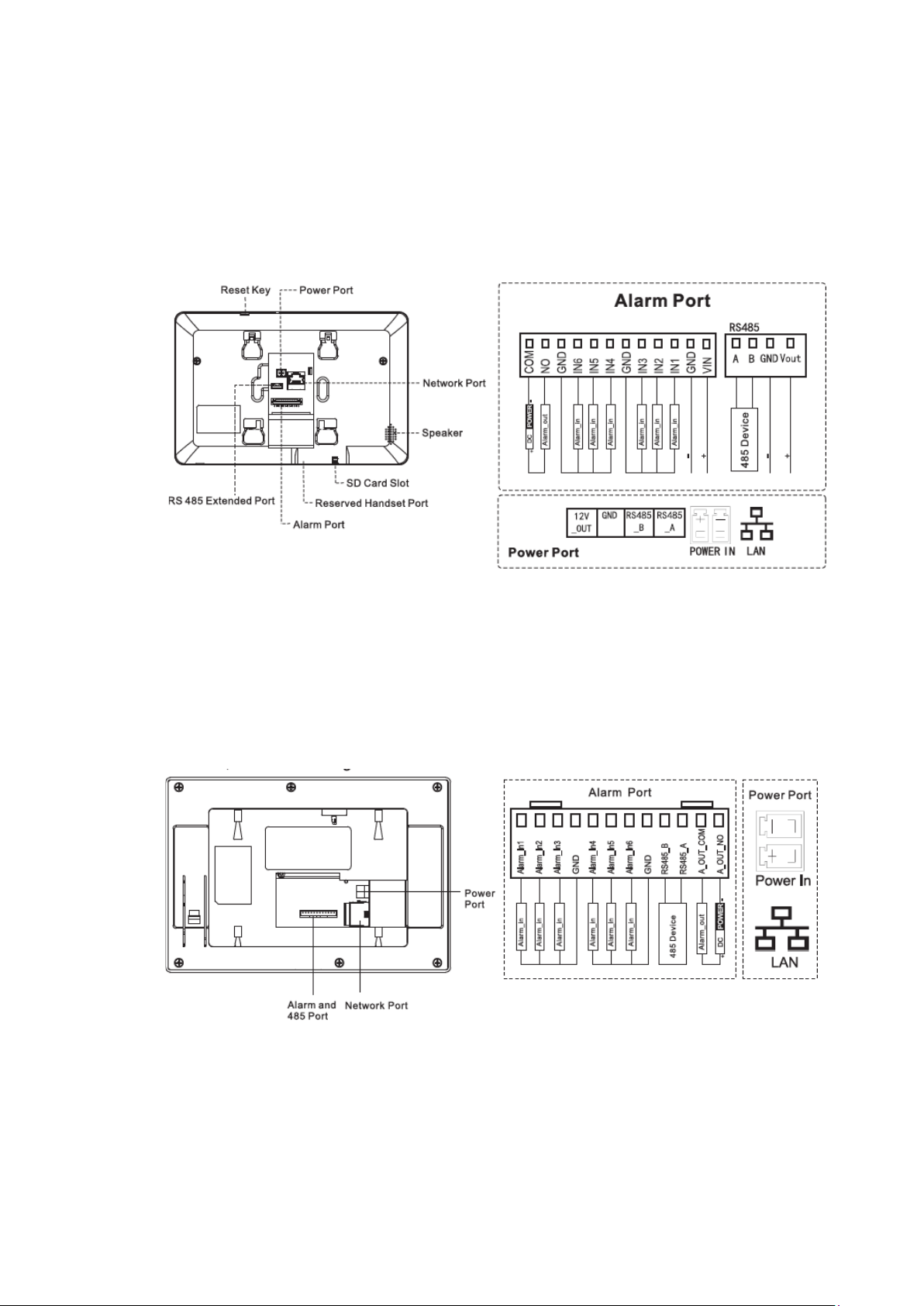
2.2.1
VUH5221 Series/VUH5241 Series
Port positions are slightly different on the rear panel of VUH5221 series and VUH5241 series,
but the same port owns the same function. Taking VUH5221 as an example, specific functions
of ports are introduced, as shown in Figure 2-7.
Figure 2-7
2.2.2
VUH15 Series Type A/ Type B/ Type CH
In VUH15 series, different types of digital VUH have different port positions, but the same port
owns the same function. Taking VUH1550CH as an example, specific functions of ports are
introduced, as shown in Figure 2-8.
Figure 2-8
In VUH type A/type B series, different types of digital VUH have different port positions, but the
same port provides the same function. Taking VUH1560B as an example, specific functions of
ports are introduced, as s hown in Figure 2-9.
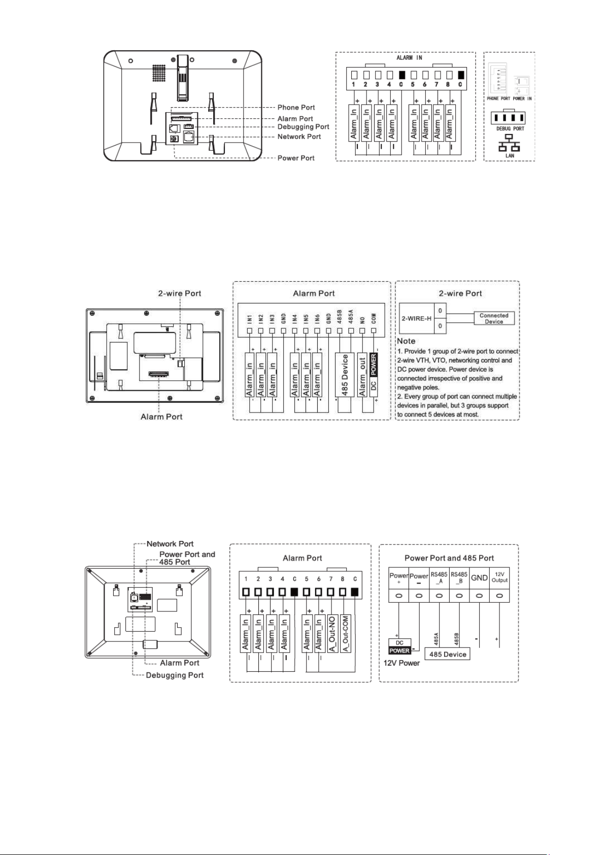
10
Figure 2-9
2.2.3
VUH5222CH
VUH5222CH 2-wire VUH provides 6 alarm input ports, 1 alarm output port, 1 RS 485 port and
1 group of 2-wire port, as shown i n Figure 2-10. VUH1550CHW-2 has 3 groups of 2-wire port.
Figure 2-10
2.2.4
VUH1660CH
VUH1660CH digital VUH provides 8 alar m input ports, 1 RS485 port, 1 debugging port, 1
network port and power p or t , as shown in Figure 2-11.
2.2.5
Figure 2-11
VUH2221A
VUH2221A digital VUH provides 8 alarm input ports, 1 network port and power port, as shown
in Figure 2-12.
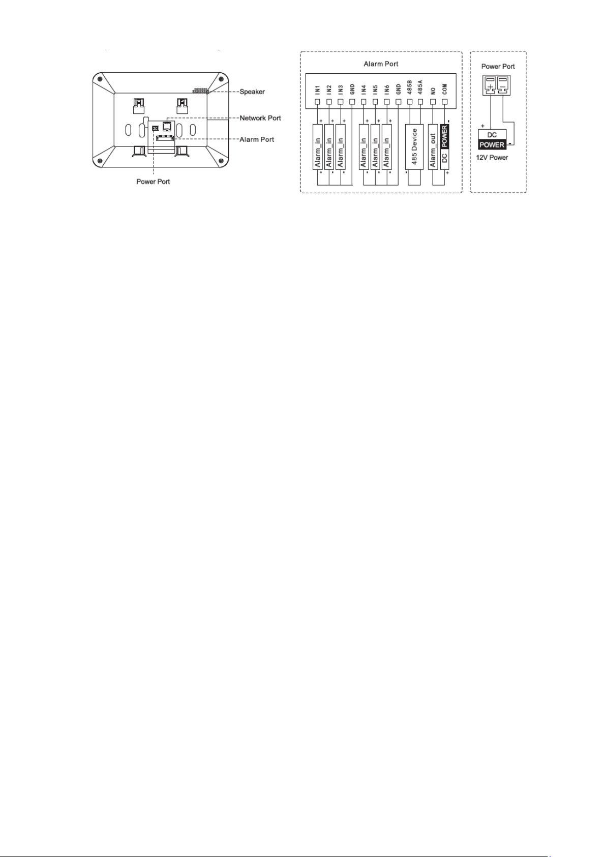
11
Figure 2-12
12
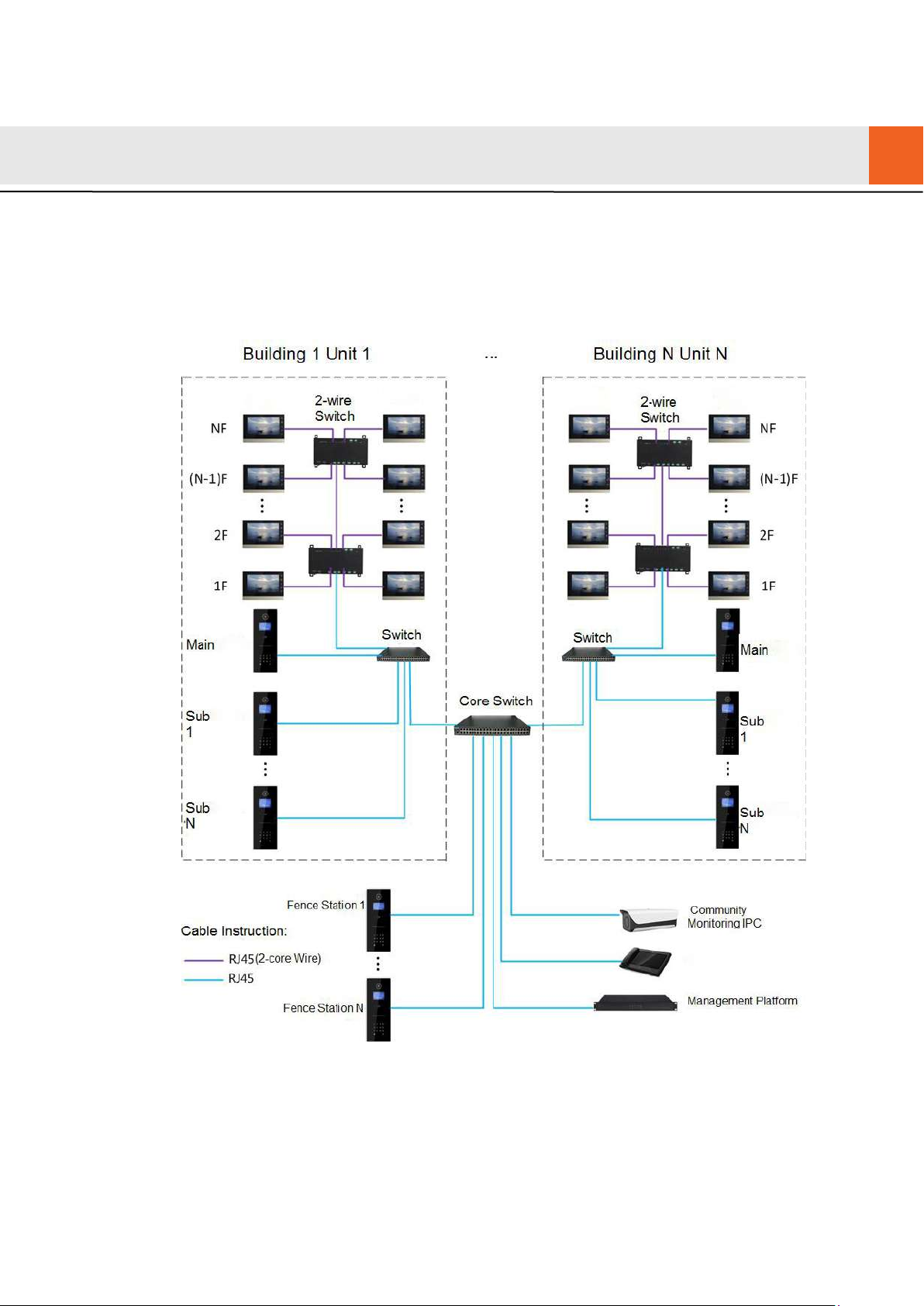
3.1
3
Network Diagram
2-wire System
Network diagram of 2-wire system is shown in Figure 3-1.
Figure 3-1
13
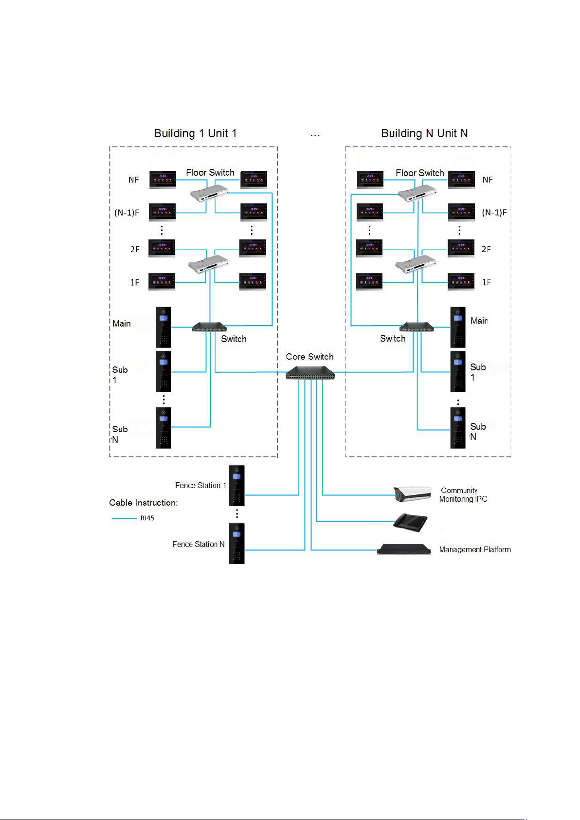
3.2
Digital System
Digital system networ k co nsist of two types:
VUH adopts PoE power supply from floor switch, as shown in Figure 3-2.
Figure 3-2
VUH adopts independent power s upply from power supply dev ice, as show n in Figure 3-3.
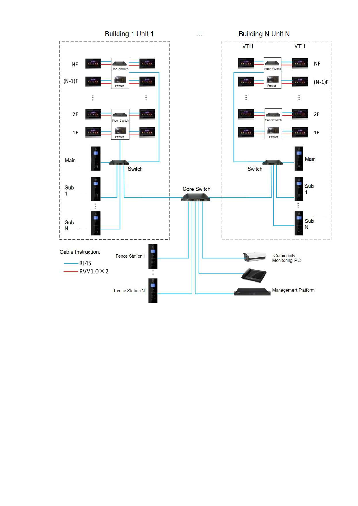
14
Figure 3-3
15
4.1
4 Device Installation
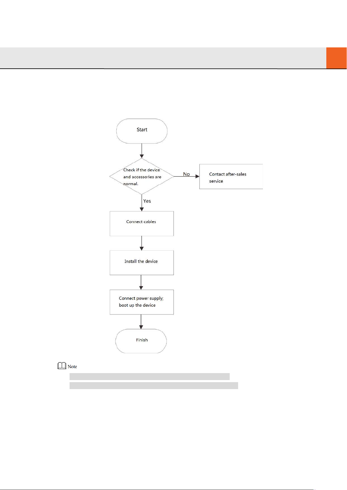
Installation Flow Chart
VUH installation flow chart is show n i n Figure 4-1 Please insta ll VUH in the following steps.
4.2
Figure 4-1
For cable connection, please r ef er t o “2.2 Rear Panel Port”.
For device installation, ple ase r ef er t o “4.4 Device Installation”.
Open-case Inspection
Please carry out open-cas e inspection when receiving the dev ice. Please timely contact our
16
after-sales service personnel in case of any problems.
Sequence
Item
Content
Fittings
Inspect whether fittings are complete.
Inspect whether it is consis t ent with order
Inspect whether it is torn o r dam aged.
3
Device
Appearance
Inspect whether there are obvious damages.
Appearance Inspect w het her there are obvious damages.
1
Overall
package
Package
Inspect
impacts.
whether there are accidental
4.3
Device model
2
Installation Requirement
Don’t insta ll VUH in bad environment, such as condensation, high temperature, stained,
dusty, chemically corrosive and direct sunshine environment.
Engineering installation and debugging shall be done by pr ofessional teams. Please don’t
dismantle or repair arbitrarily in case of device failure.
Model
and label
Label
device
on the
Table 4-1
contract.
Don’t tear or discard the label, otherwise
warranty service won’t be provided. When
dialing our after-sales hotline, please provide
serial number of the product.
4.4
Device Installation
It is suggested that installat ion h eight of device central point sha ll be 1. 4cm~1.6cm above the
ground.
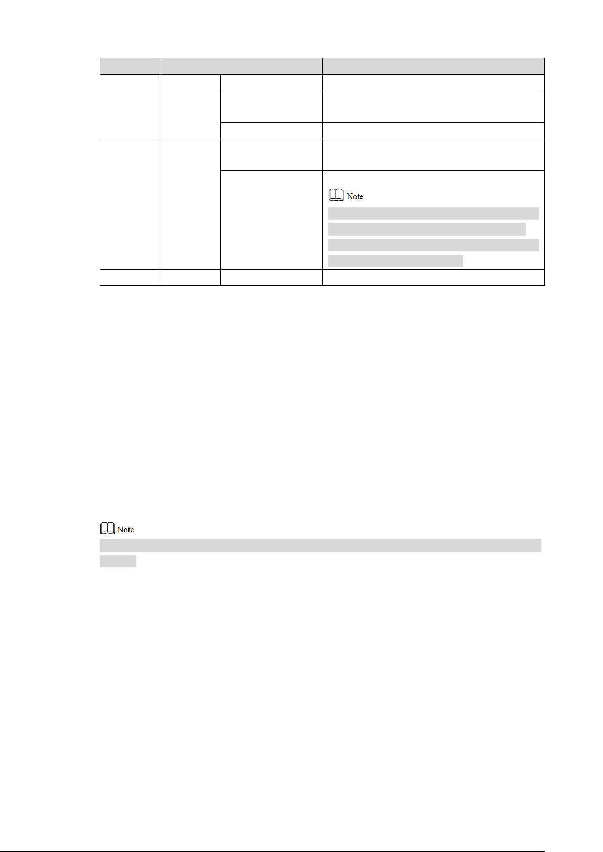
4.4.1
Surface Installation
Directly install the device with a bracket onto a wall, which is suitable for all types of devices.
Take “VUH1550CH” for example.
Step 1 Drill holes in the wall according to hole positions of the bracket.
Step 2 Fix installation bracket dir ec t ly onto the wall with screws.
Step 3 Put the device into installation bracket from top down.
17
Figure 4-2
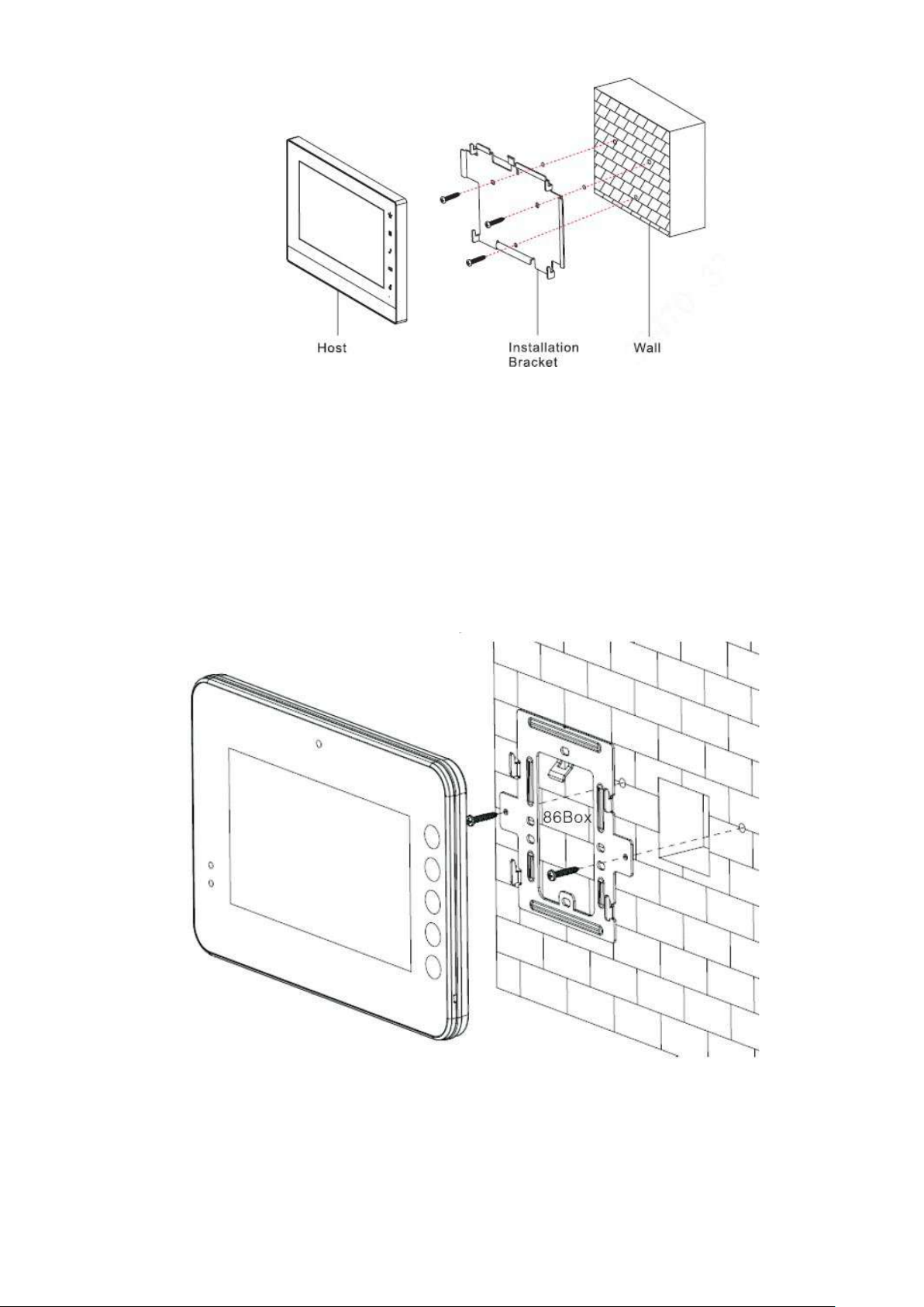
4.4.2
Installation with 86 Box
Install the device with 86 box, w hich is suitable for all types of device s. Take “VUH1560B/BW”
for example.
Step 1 Embed 86 box into a wall at a proper height.
Step 2 Fix installation bracket ont o 86 box w it h screws.
Step 3 Put the device into installation bracket from top down.
Figure 4-3
18
5.1
5 Device Debugging
Carry out debugging to ensure that the device can realize basic network access, call and
monitoring functions after installation. Before debugging, please check whether the following
work has been completed.
Check whether there is short circuit or open circuit. Power on t he device only after the
ci
rcuit is confirmed to be normal.
IP and no. of every VUO and VUH have been planned.
Debugging Settings
Set VUO info and VUH info at WEB interface of every VUO, set VUH info, network info and
VUO info on every VUH, and thus r ealize video intercom function.
5.1.1
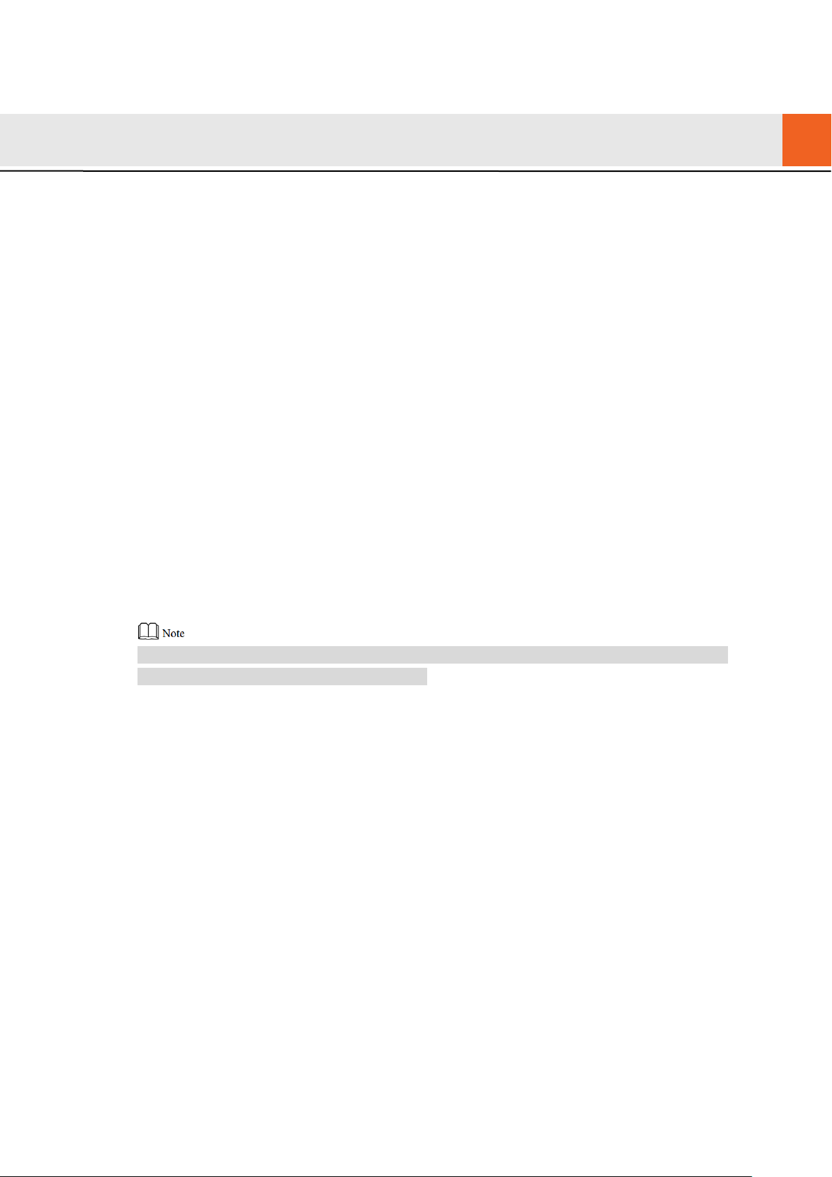
5.1.1.1 Initialization
VUO Settings
For the first time, please init ia lize and modify login password.
Please ensure that defau lt I P addr esses of PC and VUO are in the same network segment.
Default IP address of VUO is 192.168. 1. 110.
Step 1 Connect VUO power and boot up.
Step 2 Enter default IP address of VUO at the address bar of PC browser.
The system displays “Sett ing” interface, as shown in Fig ur e 5-1.
19
Figure 5-1
Step 3 Enter “New Password” and “ Confirm”, and click “Next”.
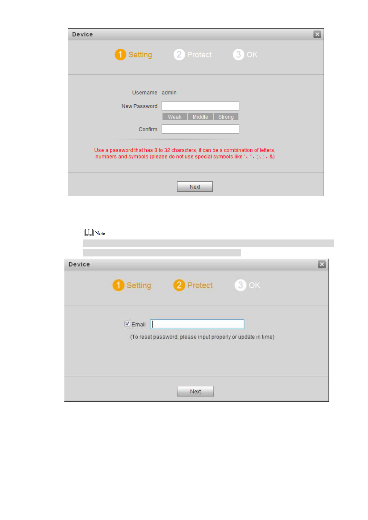
The system displays “Prot ect ” int er f ace, as s hown in Figure 5-2.
This password is used to login WEB interface. It shall be at least 8 ch ar act er s , and shall
include at least two types of nu m ber , lett er and symbol.
Figure 5-2
Step 4 Select “Email” and enter your Email address.
This Email address is used to reset the password, so it is recom m ended that it should
be set.
Step 5 Click “Next”.
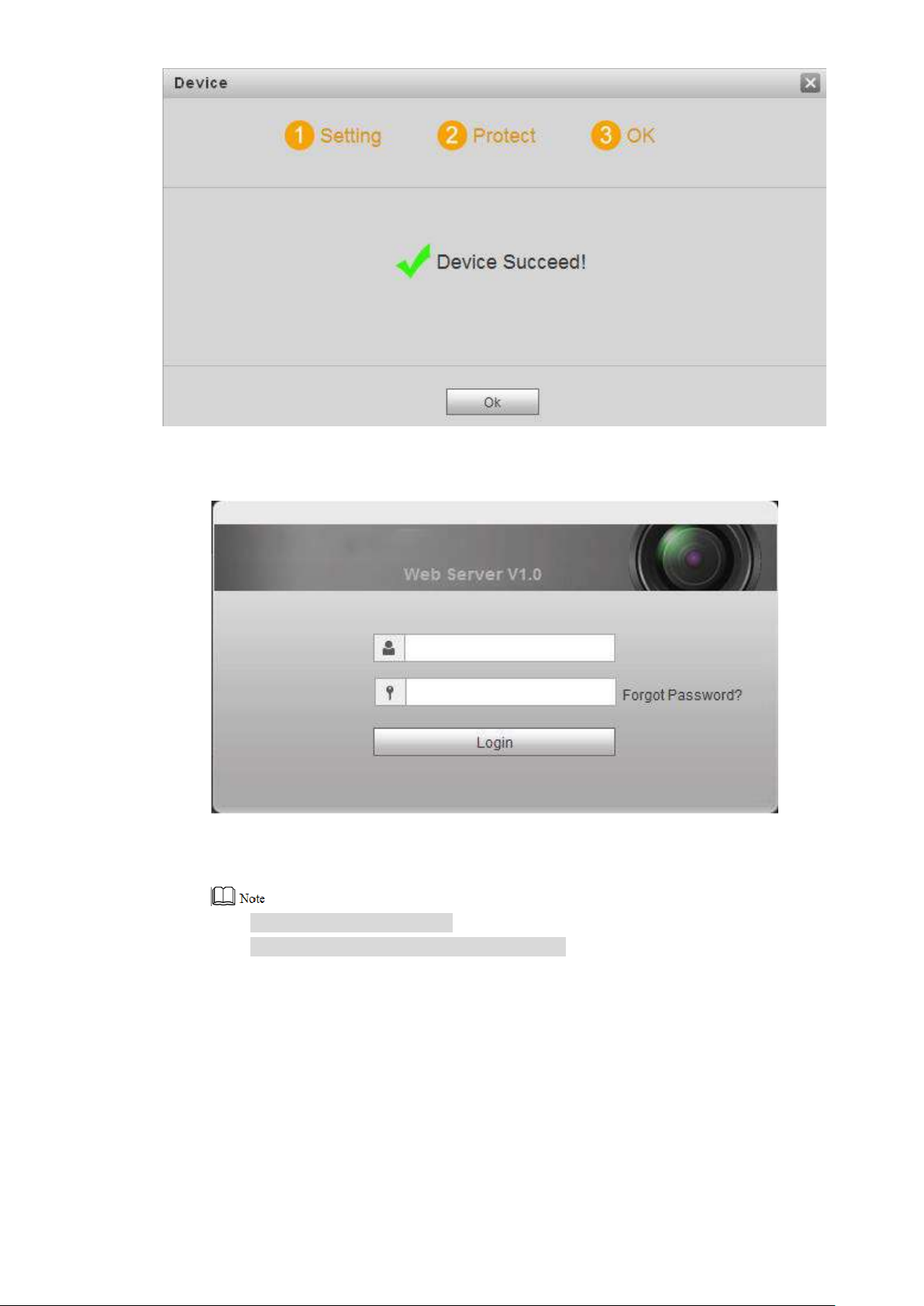
The system displays “OK” inter fa c e, as shown in Figure 5-3, and shows “Device
succeeded!”
20
Figure 5-3
Step 6 Click “OK”.
The system displays WEB login interface, as shown in Figure 5-4.
Figure 5-4
Step 7 Enter user name and password, and click “Login”.
Log in the WEB interface of the device.
Default user name is admin.
Password is the one set during initialization.
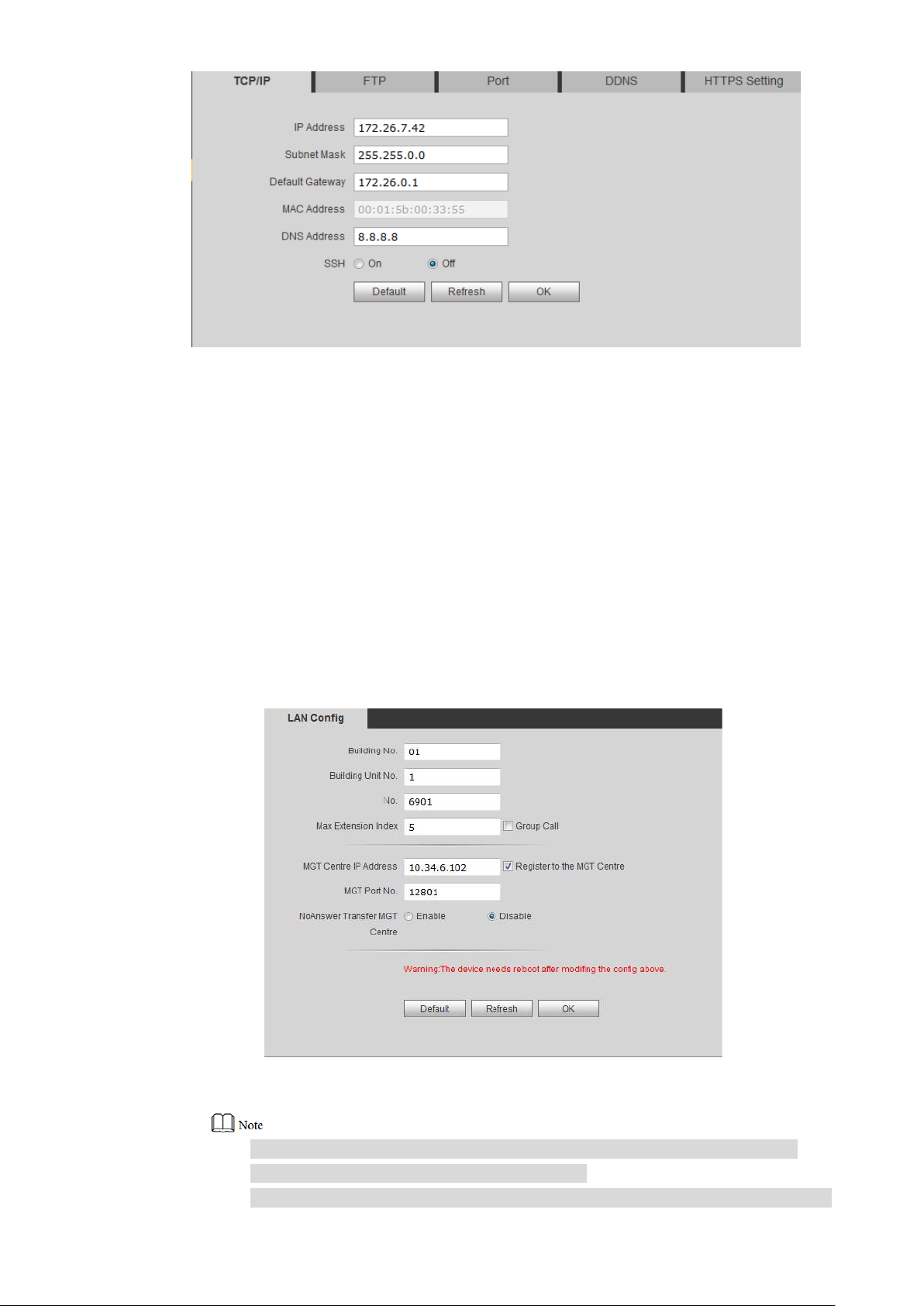
5.1.1.2 Network Config
Modify IP address of VUO to be planned IP address.
Step 1 Select “System Config > Network Config > TCP/IP”.
The system displays “TCP/IP” interface, as shown in Figure 5-5.
21
Step 2 Enter the planned “IP Address”, “Subnet Mask” and “Default Gateway”, and click “OK”.
After modification is completed, VUO reboots automatically, while the following two
cases occur at WEB interface.
If PC is in the planned network segment, WEB interface jumps to new IP login
nterface automatically.
i
If PC is not in the planned netw or k segment, the webpage cannot be displayed.
Please add PC into the planned net work segment and login WEB interface again.
5.1.1.3 LAN Config
Set building no., unit no. and VUO no..
Step 1 Select “System Config > LAN Config”.
The system displays “LA N Config” interface, as shown in Figure 5-6.
Figure 5-5
Figure 5-6
Step 2 Enter VUO “Building No.” , “ Bui ld ing Unit No.” and “VUO No.”.
To call management centre, please s elect “Register to the MGT Centre”; set
“MGT Centre IP Address” and “ M G T Port No.”.
To provide group call, please select “Group Call” and set “Max Extension Index”

22
Step 3 Click “OK”.
5.1.1.4 Add VUH
Add VUH info. After VUH and VUO debugging is completed, VUH will be regis t er ed t o VUO
automatically, in order to realize binding.
Add master VUH only.
After “Network Terminal” inter face of extension VUH adds main VUO and enables it, VUO
interface will obtain extens ion VUH info automatically.
Step 1 Select “System Config > Di gital Indoor Station Manager”.
The system displays “Digital Indoor Station Manager ” int erface, as shown in Figure 5-
7.
which can be 5 at most.
Figure 5-7
Step 2 Click “Add”.
The system displays “Add ” inter face, as shown in Figure 5-8.
Figure 5-8
Step 3 Enter VUH “Family Name”, “First Name”, “Nick Name”, “VUH Short No.” (VUH room no.)
and “IP Address”.
It is OK if IP address is not filled in. A ft er VUH is reg i s t er ed t o VUO successfully, VUO
will obtain IP address of VUH.
Step 4 Click “OK”.

23
5.1.2
VUH Config
5.1.2.1 Initialization
Set the password and bind y our Email.
Password: it is used to ent er project setting interface.
Email: it is used to retriev e your password when you forget it.
Step 1 Power on the device.
The system displays “Welcome” and enters “Device I nitial iz ation” interface, as shown
in Figure 5-9.
Step 2 Enter “Password”, “Confirm Pwd” and “Email”. Click [OK].
The system displays main inter fa ce.
5.1.2.2 Network Config
According to available network connection modes, conf ig ur e VUH net w ork information.
IP addresses of VUH and VUO s hall be in the same network segment. Otherwise, VUH will fail
to obtain VUO info after configuration.
Step 1 Press [Setting] for more th an 6 seconds.
The system pops up “Password” prompt box.
Step 2 Enter the password set during init i al ization, and click [OK].
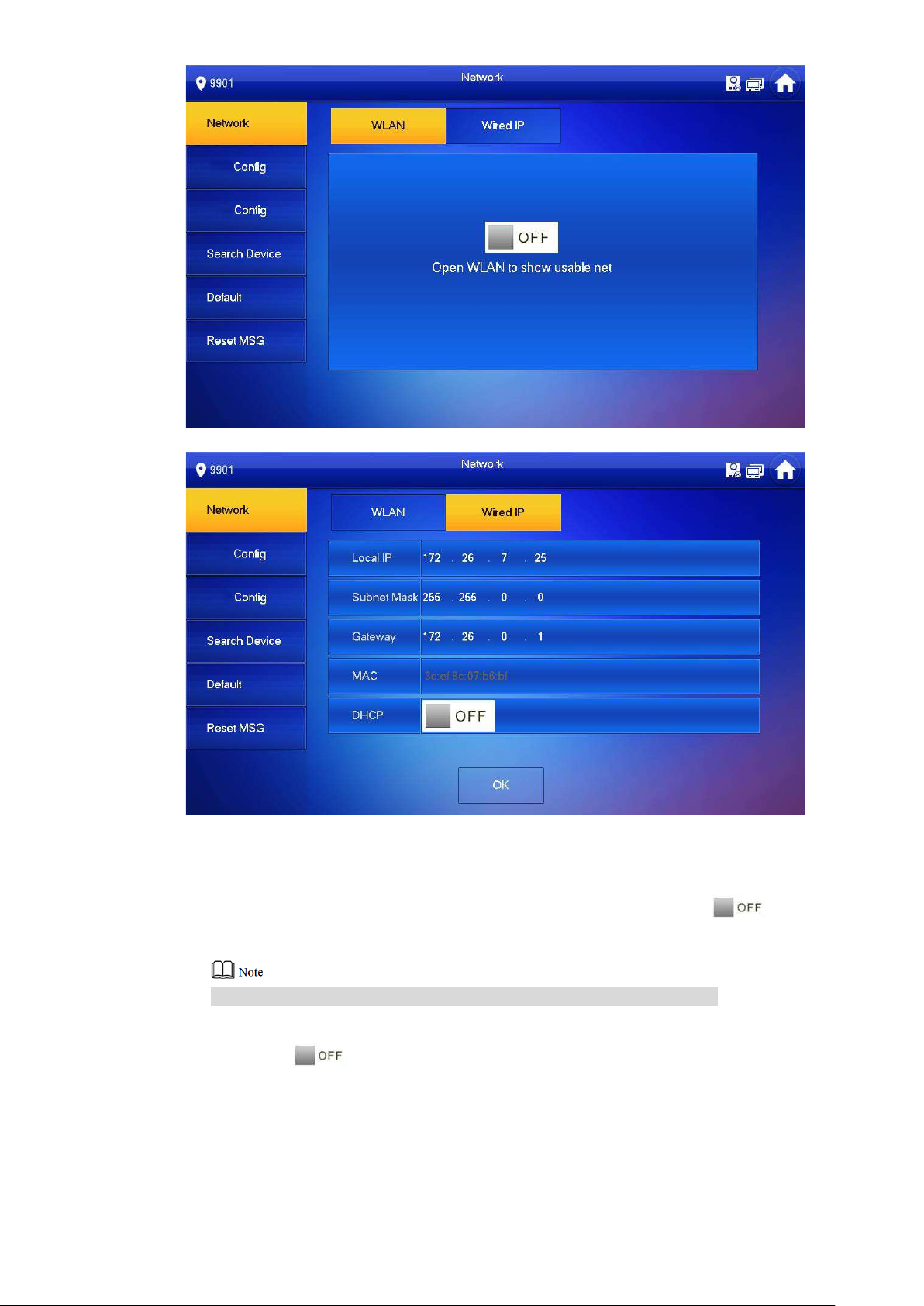
Step 3 Click [Netw o rk].
The system displays “Network” interface, as shown in F igure 5-10 and Figure 5-11
Only devices with the wireless function can access to wirele ss net work.
Figure 5-9
.
24
Figure 5-10
Figure 5-11
Step 4 Set according to actual net w or k acces s mode.
Wired IP
Enter “Local IP”, “Subnet M ask” and “Gateway”, press [OK] . O r pr ess to enable
DHCP function and obtain I P info automatically.
If the device has wireless funct ion, please click “Wired IP” tab t o set it .
WLAN
1. Press to enable WIFI function.
The system displays available WIFI list, as s how n i n Figure 5-12.

25
Figure 5-12
2. Connect WIFI.
The system has 2 access ways as follows.
◇ At “WLAN” interface, select WIFI, click “Wireless IP” tab to ent er “ Local IP” ,
“Subnet Mask” and “Gateway”, and press [OK].
◇ At “WLAN” interface, select WIFI, click “Wireless IP” tab, pres s to
enable DHCP function and obtain IP info automatic ally , as show n in Figure
5-13.
To obtain IP info with DHCP fun ct ion, use a router with DHCP function.
Figure 5-13
5.1.2.3 VUH Config
Set VUH “Room No.”, type and “Master IP”.
Step 1 Press [Setting] for more th an 6 seconds.

26
The system pops up “Password” prompt box.
Step 2 Enter the password set during init i al ization, and click [OK].
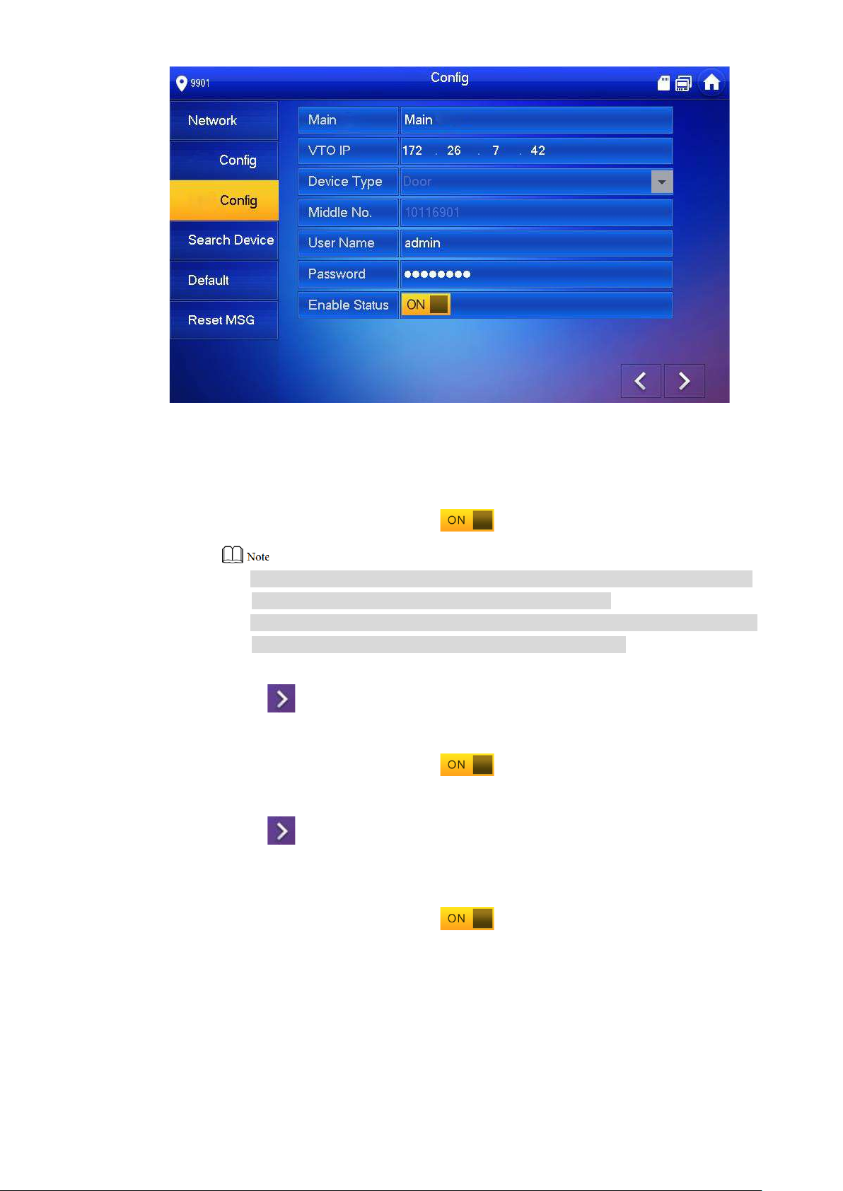
Step 3 Click [VUH Config].
The system displays “VUH Config” int erface, as shown in Figure 5-14.
Step 4 Set VUH info.
Be used as a master VUH.
Enter “Room No.” (such as 9901).
“Room no.” shall be the same with “ VUH Shor t No. ”, which is set when adding VUH at
WEB interface. Otherwise, it will fail to connect VUO.
Be used as an extension VUH.
1. Press [Master] and switch to “Extension”.
2. Enter “Room No.” (such as 9901-1) and “Mas t er I P” (IP address of master VUH).
“Master Name” and “Master Pwd” are the user name and password of master VUH.
Default user name is admin, and the password is the one set during device
initialization.
Step 5 Press [OK] to save settings.
5.1.2.4 VUO Config
Figure 5-14
Add VUO and fence st at ion info; at VUH interface, bind VUH with
VUO. Step 1 Press [ Setting] for more than 6 seconds.
The system pops up “Pass w or d” pr ompt box.
Step 2 Enter the password set during init i al ization, and click [OK].
Step 3 Click [VUO Config].
The system displays “VUO Config” int erface, as shown in Figure 5-15.
27
Step 4 Add VUO or fence station.
Add main VUO.
1. In Figure 5-15, enter main VUO name, VUO IP, “User Name” and “Password”.
2. Switch the “Enable Status” to be .
“User Name” and “Password” shall be c onsistent with WEB login user name
and password of VUO. Otherwise, it will fail to connect.
“Enable Status” of main VUO is “ON” by def ault. After setting VUO info, it will
take effect after turning it of f and then turning it on again.
Add sub VUO.
1. Press to switch to sub VUO setting interface.
2. Enter sub VUO name, IP address, “User Name” a nd “Password”.
3. Switch the “Enable Status” to be .
Add fence station.
Figure 5-15
1. Press to switch to sub VUO setting interface.
2. Select device type to be “Fence Station”, ent er Sub VUO name (fenc e st ation
name), middle no. (fence st at ion no.), “User Name” and “Password”.
3. Switch the “Enable Status” to be .
28
5.2
Debugging Verification
5.2.1
VUO Calls VUH
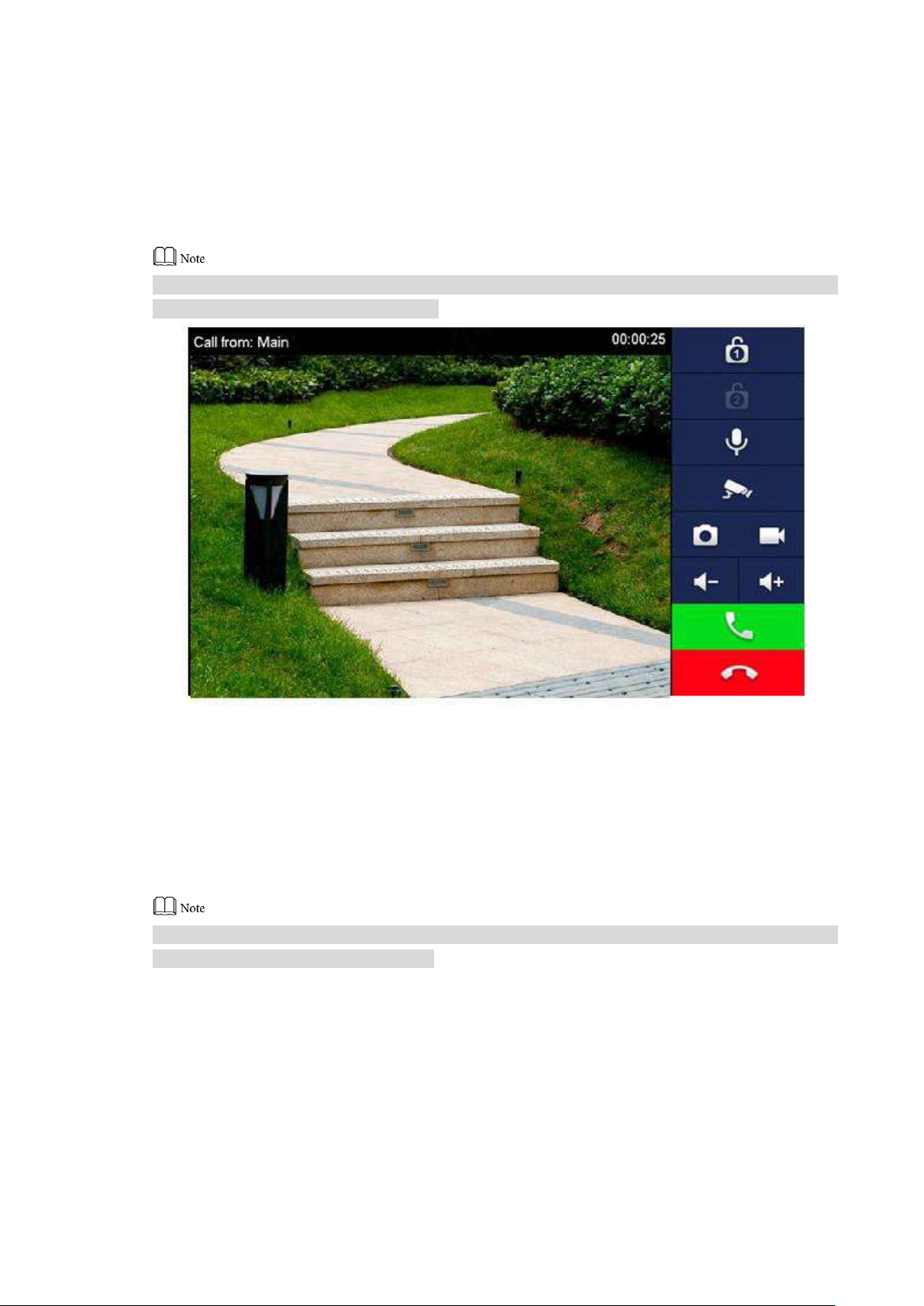
Dial VUH room no. (such as 9901) at VUO, and thus cal l VUH. VUH pops up monitoring imag e
and operating keys, as sh ow n in F igure 5-16. It represents successful debugging.
The following figure mean s t hat SD card has been inserted into VUH. If SD card is not inser ted,
recording and snapshot icons are gray.
5.2.2
Figure 5-16
VUH Monitors VUO
VUH is able to monitor VUO, fence station or IP C. Take “VUO” for example.
Select “Monitor > Door”, as shown in Figure 5-17. Select the VUO to enter monitoring image,
as shown in Figure 5-18.
The following figure mean s t hat SD card has been inserted into VUH. If SD card is not ins erted,
recording and snapshot icons are gray.

29
Figure 5-17
Figure 5-18

30
6.1
No.
Name
Description
View, delete and clear notices issued by Property Management
audio message uploading function, “Guest Message” tab will be
6 Interface Operation
Main Interface
There are six items at the main inter f ac e, namely, call, info, monitor, SOS, setting and
arm/disarm, as shown in Figur e 6-1. For description of every item, pl ease refer to Table 6-1.
Figure 6-1
1 Room No. Number of the room where VUH is located.
Call a user.
2 Call
3 Info
Manage the contacts.
View and manage the call records.
Center.
View, delete and clear security alar m info.
When VUH doesn’t have a SD card or VUO enables video-
displayed. View, delete and clear messages of VUO.
When VUH owns a SD card, “Video Pic” tab will be displayed.
View, delete and clear vid eos and pictures.

31
No.
Name
Description
: Wired network connection icon, meaning that the device
: Wired network connection icon, meaning that the device
Fi network connection icon, meaning that the device
; without this icon, the device has
5
Time
Display date, day of the week and time.
Display the last unread alarm info.
Press [Setting], input login password and enter system setting
8
SOS
Press this icon to call Man agement Center.
9
Monitor
Monitor the VUO, fence station, IPC, NVT, DVR and UVR.
isn’t connected with network.
has connected with netwo r k in a w ired way.
: W i-
has connected with netwo r k in a w ireless way.
4 Status Bar
6 Arm/disarm
7 Setting
: Main VUO connection icon, meaning that the device failed
to connect main VUO
connected with main VUO successfully.
: SD card icon, meaning th at SD card has been inserted into
the device; without this icon, t he SD card has not been inserted
or the device doesn’t support SD card.
: DND (Do Not Disturb) icon, meaning that the device has
enabled DND function. It is not enabled by default.
: press this icon to enter arm mod e selection.
interface.
Press [Setting] for over 6 sec onds, input the password set
during initialization, and e nt er pr oje ct s et t ing i nt er f ace.
6.2
Setting
6.2.1
Ring Settings
Set VUO ring, VUH ring, alarm ring and other rings.
6.2.1.1 VUO Ring
Set a ring for the connected VUO, and support to set maximum 20 VUOs.
Step 1 Press [Setting].
Table 6-1

32
The system pops up “Password” prompt box.
Step 2 Input login password and pr ess [OK].
Default login password is 123456. Please refer to “6.2.5.3 Password Setting” for
details.
Step 3 Select “Ring > VUO Ring”.
The system displays “VUO Ring” interface, as shown in Figure 6-2. Press or
to page up and down.
Step 4 Press text box to select rings, and press and to set the volume.
6.2.1.2 VUH Ring
Set the ring of this VUH.
Step 1 Press [Setting].
The system pops up “Password” prompt box.
Step 2 Input login password and pr ess [OK].
Default login password is 123456. Please refer to “6.2.5.3 Password Setting” for
details.
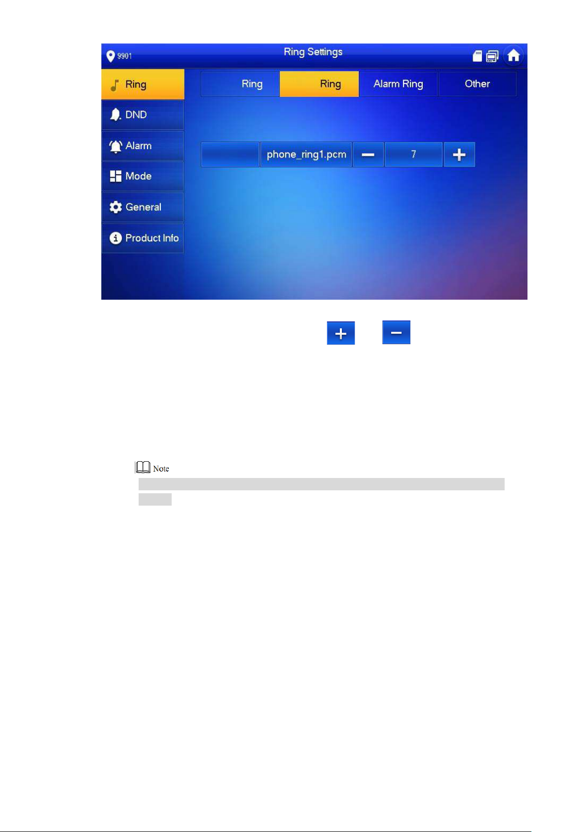
Step 3 Select “Ring > VUH Ring”.
The system displays “VUH Ring” interface, as shown in Figure 6-3.
Figure 6-2
33
Step 4 Press text box to select rings, and press and to set the volume.
6.2.1.3 Alarm Ring
Set the ring when VUH gives an alarm.
Step 1 Press [Setting].
The system pops up “Password” prompt box.
Step 2 Input login password and pr ess [OK].
Default login password is 123456. Please refer to “6.2.5.3 Password Setting” for
details.
Step 3 Select “Ring > Alarm Ring”.
The system displays “Alar m Rin g” int erface, as shown in Figure 6-4.
Figure 6-3

34
Step 4 Press text box to select rings, and press and to set the volume.
6.2.1.4 Other
Set VUO ring time, VUH ring time, MIC volume, talk volume and ring mute setting.
Step 1 Press [Setting].
Step 2 Input login password and pr ess [OK].
Step 3 Select “Ring > Other”.
Figure 6-4
The system pops up “Password” prompt box.
Default login password is 123456. Please refer to “6.2.5.3 Password Setting” for
details.
The system displays “Other” interface, as shown in Figur e 6-5.

35
Figure 6-5
Step 4 Press and to set the time or volume. Press to enable “Ring
Mute”, and the icon become s .
“VUO Ring Time” and “VUH Ring Time” of the extension VUH are synchroniz ed
with master VUH, and cannot be set.
VUO ring time: ring ti me when VUO calls VUH.
VUH ring time: ring time when another VUH calls this VUH.
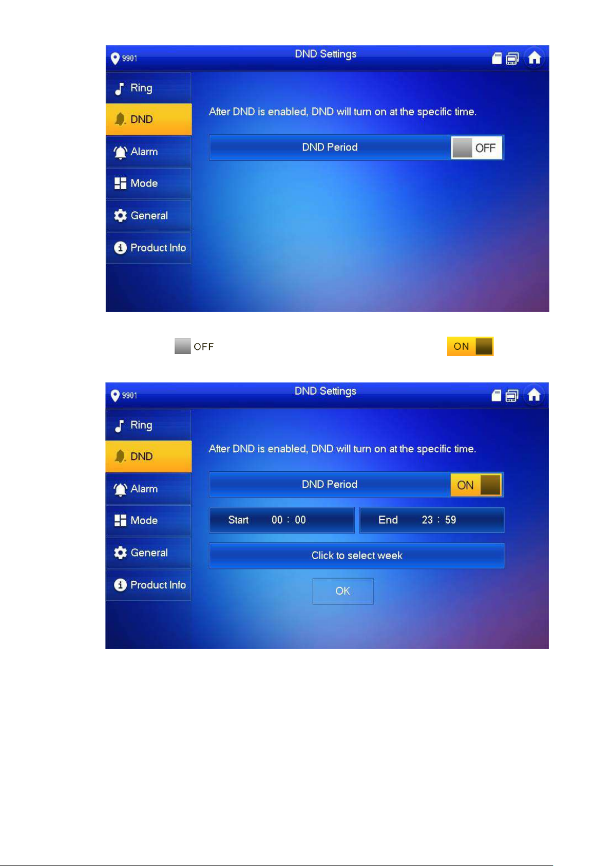
6.2.2
DND Settings
Set to avoid incoming call s w it hin a time period.
DND function is not enabl ed by default.
Under DND mode, there is no c al l reminder when VUH is called, but call in fo is recorded.
Parameters at this interfa ce are set on master VUH only, and extension VUH
synchronizes with master VUH.
Step 1
Step 2
Step 3
Press [Setting].
The system pops up “Password” prompt box.
Input login password and pr ess [ O K] .
Default login password is 123456. Please refer to “6.2.5.3 Password Setting” for
details.
Press [DND].
The system displays “DND Sett i ngs ” interface, as shown in Figur e 6-6.
36
Figure 6-6
Step 4
Press to enable DND function, and the icon becomes .
The system displays DND per iod, as shown in Figure 6-7.
6.2.3
Figure 6-7
Step 5
Step 6
Step 7
Press time text box; set start time and end time.
Press [Click to select week] and select DND week.
Press [OK] to save settings.
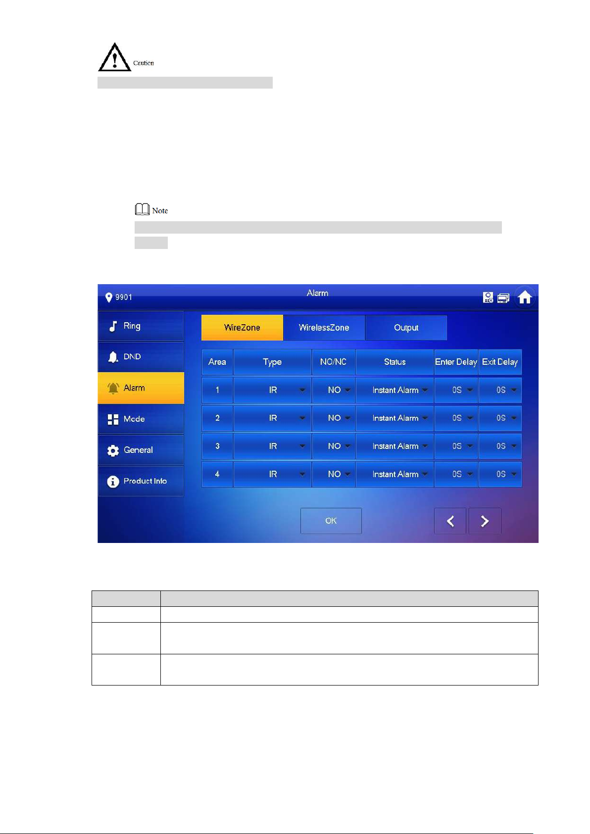
Alarm Setting
Set wire zone, wireless zone and alarm output.
37
Zones can be set under disarm mode.
Parameter
Description
Area No.
The number cannot be modified.
Select NO (normally open ) or NC (normally closed) according to detector type. It
6.2.3.1 Wire Zone
Set zone type, NO/NC, al ar m stat us and delay. It supports to set 8 z ones at most.
Step 1
Step 2
Step 3
Press [Setting].
The system pops up “Password” prompt box.
Input login password and pr ess [ O K] .
Default login password is 123456. Please refer to “6.2.5.3 Password Setting” for
details.
Select “Alarm > Wire Zone”.
The system displays “Wire Zone” interface, as shown in Figure 6-8.
Figure 6-8
Step 4 Press corresponding positions to set zone type, NO/NC, alarm status, enter delay and
exit delay. Please refer to Table 6-2 for details.
NO/NC
Type
shall be the same as detect or t ype.
Select corresponding type according to detector ty pe, including IR, gas, smoke,
urgency btn, door, burglar alarm, perimeter and doorbell.
38
Parameter
Description
It includes instant alarm, delay alarm, bypass and remove.
Instant alarm: in case of al ar m a fter arm, produce alarm sound at once and
After entering delay, when armed area triggers an alarm,
armed area within the
delay time period will not lead to linkage alarm. Linkage
After arm, “delay alarm” ar ea will enter arm status at the
ers alarm status.
ent
Delay alarm: in case of alar m a fter arm, enter alarm status after some time.
Within the time period, y ou can disarm and cancel the alarm.
Status
Bypass: this area is shielded from this arm. After disarm, this ar ea will
restore normal working status.
Remove: this area is invalid during arm/disarm.
An zone under “Remove” status cannot be bypassed.
entering armed area from non-
Enter Delay
alarm will be produced if delay t ime comes to an end and
it is not disarmed.
end of “exit delay”.
Exit Delay
If multiple areas set the ex it delay, interface prompt will
conform to maximum delay time.
Step 5 Press [OK] to complete setting.
Delay is only valid
to the areas of
“delay alarm”.
Table 6-2
6.2.3.2 Wireless Zone
Only devices with wireless function have this functio n.
Add, delete and set wireles s zones.
Step 1
Step 2
Step 3
Press [Setting].
The system pops up “Password” prompt box.
Input login password and pr ess [ O K] .
Default login password is 123456. Please refer to “6.2.5.3 Password Setting” for
details.
Select “Alarm > Wireless Zone”.
The system displays “Wireless Zone” interface, as show n in Figure 6-9.

39
Step 4 Press [Add].
Step 5 Press wireless code button of wireles s device. Please refer to wireless device user’s
manual for details.
After successful coding, di splay area info.
Step 6 Press corresponding positions to set alarm status, ent er delay and exit delay. Please
refer to Table 6-2 for details.
Press [Edit] to select a zone and press [Delete] to delete the s elected area.
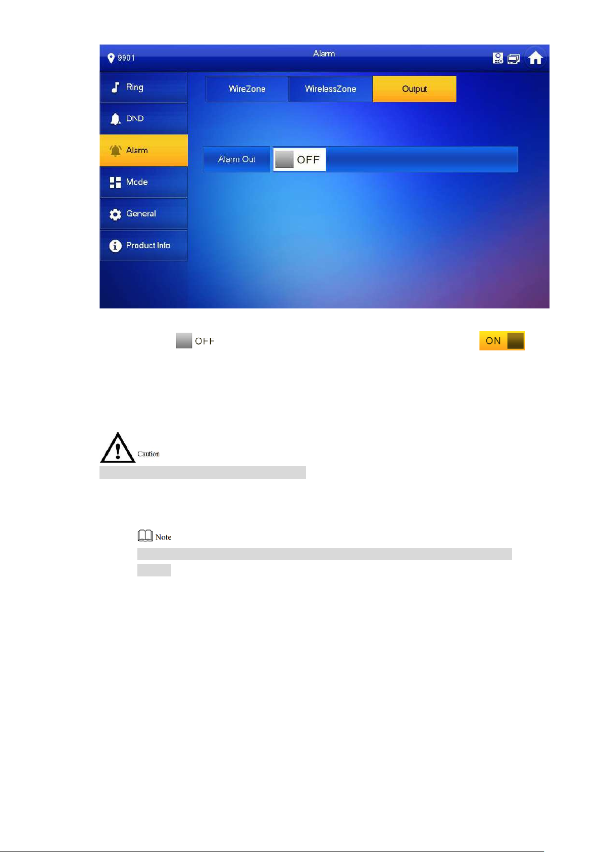
6.2.3.3 Alarm Output
After enabling alarm outp ut , w hen other devices call this VUH, the alarm outp ut device will
output alarm info.
Step 1
Step 2
Step 3
Press [Setting].
The system pops up “Password” prompt box.
Input login password and pr ess [ O K] .
Default login password is 123456. Please refer t o “6.2.5.3 Password Setting ” for
details.
Select “Alarm > Output”.
The system displays “Output” interface, as shown in Figure 6-10.
Figure 6-9
40
Step 4 Press to enable alarm output function, and t he ic on becomes .
6.2.4 Mode Setting
Set area on/off status und er different modes.
Area mode can be set only in disarm status.
Step 1
Step 2
Step 3
Press [Setting].
The system pops up “Password” prompt box.
Input login password and pr ess [ O K] .
Default login password is 123456. Please refer to “6.2.5.3 Password Setting” for
details.
Press [Mode].
The system displays “Mode” interface, as shown in Figure 6-11.
Figure 6-10

41
Step 4 Select arm mode in every tab.
Step 5 Press in every area to add it into arm mode.
Multiple areas can be added int o one arm mode simultaneously, whereas one area can
be added into different modes.
6.2.5 General Setting
Set VUH time, display, user password and ot hers.
6.2.5.1 Time Setting
Set VUH system time, time zone and DST.
Parameters at this interfa ce are set on master VUH only, and exten si on VUH synchronize with
master VUH.
Step 1
Step 2
Press [Setting].
The system pops up “Password” prompt box.
Input login password and pr ess [ O K] .
Figure 6-11
Step 3
Default login password is 123456. Please refer to “6.2.5.3 Password Setting” for
details.
Select “General > Time”.
The system displays “Tim e” int erface, as shown in Figure 6-12.

42
Step 4 Set time parameter.
When system time switch is , obtain server time by default; w hen it is
, set system time, time zone and DST manually.
Manual setting of system time
1. Press of system time and the icon becomes , so as to enable
manual setting function.
2. Press time text box to set system time.
Setting of time zone
1. Press of system time and the icon becomes , so as to enable
manual setting function.
2. Press time zone text box, and select local time zone, as shown in Figure 6-13.
Figure 6-12

43
DST setting
1. Press of system time and the icon becomes , so as to enable
manual setting function.
2. Press to enable DST.
3. Press DST text box, and select DST start time and end time.
6.2.5.2 Display Setting
Set VUH screen brightness, screensav er time and clean.
Step 1
Step 2
Step 3
Press [Setting].
The system pops up “Password” prompt box.
Input login password and pr ess [ O K] .
Default login password is 123456. Please refer to “6.2.5.3 Password Setting” for
details.
Select “General > Display ”.
The system displays “Display” interface, as shown in Figure 6-14.
Figure 6-13

44
Step 4 Set parameters.
Press and ; set “Brightness” and “Screensaver Time”.
Press [Clean] and the scr een will be locked for 10 seconds. During the period,
clean the screen. It restor es after 10 seconds.
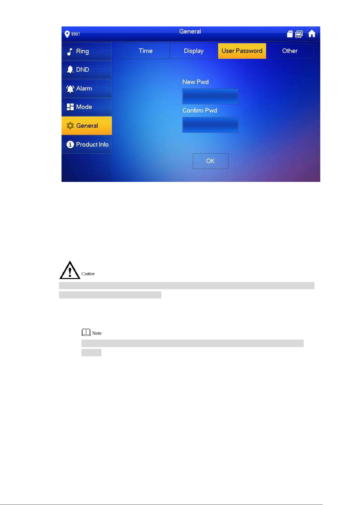
6.2.5.3 Password Setting
Set login password, arm/disarm password, unlock password and anti-hijacking password of
VUH setting interface. Login password, arm/disarm password and unlock password are 123456
by default, whereas anti-hijacking password is the re versed login password.
Parameters at this interface are set on master VUH only, and extension VUH synchronize with
master VUH.
Step 1
Step 2
Step 3
Press [Setting].
The system pops up “Password” prompt box.
Input login password and pr ess [ O K] .
Select “General > User Pass w or d” .
The system displays “Use r Passw or d” i nterface, as shown in Figure 6-15.
Figure 6-14
45
Step 4
Step 5
Enter “New Password” an d “ Con firm Password”.
Press [OK] to complete password modification.
6.2.5.4 Other Settings
Set monitor time, record time, VUO message time, VUO ta lk time, internal call enable, internal
call time, auto capture and t ouch r in g.
Extension VUH can set “Auto Captur e” and “ Touch Ring”, but other paramet ers synchronize
with master VUH and cannot be set.
Step 1
Step 2
Step 3
Press [Setting].
The system pops up “Password” prompt box.
Input login password and pr ess [OK].
Default login password is 123456. Please refer to “6.2.5.3 Password Setting” for
details.
Select “General > Other”.
The system displays “Other” interface, as shown in Figur e 6-16.
Figure 6-15

46
Step 4
Parameter
Description
Operation
Monitor
Maximum time to monitor VUO, IPC, fence station, DVR, NVR
to set the
Maximum recording ti me of v ide os during call, talk, monitoring
When VUO message time is not 0:
enter message status according to prompt, and save
has enabled
according to prompt, and upload the message to FTP
has not
Figure 6-16
Set parameters. Please r efer t o Table 6-3 for details.
Time
Record
Time
VUO
Message
Time
and DVR.
and speaking. The system stops recording at the end of
recording time.
If VUH with SD card doesn’t answer when VUO calls,
the message in SD card of VUH.
If VUH doesn’t have SD card, but VUO
“Leave Message Upload” and set FTP server,
“Message” tab will appear at VUH info interface. If VUH
doesn’t answer when VUO calls, enter message status
server.
If VUH doesn’t have SD card, and VUO
enabled “Leave Message Upload”, if VUH doesn’t
answer when VUO calls, hang up automatically.
When VUO message time is 0:
Hang up automatically if VUH doesn’t answer when VUO
calls, no matter whether VUH has SD card or not, no matter
whether VUO has enabled “Leave M essage Upload” or not.
Press
and
time.
If VUO sets to transfer the call to manage ment center, if VUH
doesn’t answer when VUO calls, and there is no message
prompt, the call will be transf er r ed t o m anagement center.

47
Parameter
Description
Operation
Internal
Call Time
VUO Talk
After internal call is enabled, VUH can ca ll a not her VUH.
enable the
function. The
After auto capture is enabled, 3 pictures will be captured
Touch
After enabling touch ring, ther e w il l be a ring when touching the
Maximum talk time betwe en VUH and VUH.
6.2.6
Time
Internal
Call
Enable
Auto
Capture
Ring
Maximum talk time when VUO calls VUH.
The called party enables i nt er nal c all, to realize this function.
automatically when VUO calls VUH. View them at “Info> Record
and Picture” interface.
This function is valid only w hen SD card is inserted.
screen.
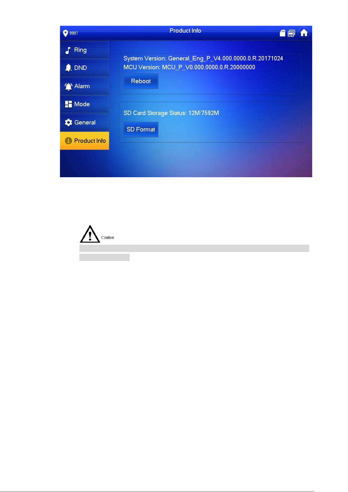
Product Info
Press
to
icon becomes
.
Table 6-3
Reboot the system and for mat SD card.
Step 1
Step 2
Step 3
Press [Setting].
The system pops up “Password” prompt box.
Input login password and pr ess [ O K] .
Default login password is 123456. Please refer to “6.2.5.3 Password Setting” for
details.
Press [Product Info].
The system displays “Product Info” interface, as shown in F igure 6-17.
48
Reboot
Press [Reboot] and press [OK] at prompt interface. The device will reboot.
SD Format
Press [SD Format] and pres s [ O K] at pr om pt int erface. The SD card will be formatted.
Before format, ensure that SD card has been inserted into the device. Otherwise, the
function is invalid.
6.3 Project Settings
Figure 6-17
6.3.1
Forget Password
If you forget initialization p assword when entering project settings interface, reset passw or d
through “Forget Password” at the interface or in VDPconfig tool.
6.3.1.1 Reset the Password at the Interface
Step 1
Step 2
Press [Setting] for over 6 sec onds.
The system pops up “Password” prompt box.
Press [Forget Password].
The system displays “QR Cod e” interface, as shown in Figure 6-18.

49
Figure 6-18
Step 3
Step 4
Step 5
Step 6
Scan the QR code with any code-scanning APP, bind your email box, send it by Email
to support_cpwd@htmicrochip.com, and t hus obt ain security code.
Press [Next].
Enter “Password”, “Conf irm Password” and obtaine d “ Security Code”.
Press [OK] to complete resetting the password.
6.3.1.2 Reset the Password in VDPconfig
Use VDPconfig tool to export XML file (ExportFile.xml), send it by email to
support_cpwd@htmicrochip.com, and obtain XML file (result.xml). Then, import the file and
reset a new password.
Please refer to “VDPconfi g Help Document” for details.
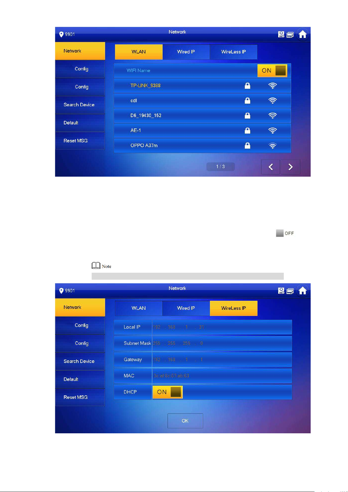
6.3.2
Network Settings
Set VUH network info according to actual conditions, since different types of devices support
different access modes.
IP addresses of VUH and VUO shall be in the same network segment. Otherwise, VUH will fail
to obtain VUO info after configuration.
Step 1
Step 2
Step 3 Press [Network].
Press [Setting] for over 6 sec onds.
The system pops up “Password” prompt box.
Enter the password set during i nitialization, and press [OK] .
The system displays “Network” interface, as shown in F igure 6-19 and Figure 6-20
Only devices with the wireless function can access to wirele ss net work.
.

50
Figure 6-19
Figure 6-20
Step 4 Set according to actual network access mode.
Wired IP
Enter “Local IP”, “Subnet M ask” and “Gateway”, press [OK] . O r pr ess to enable
DHCP function and obtain I P info automatically.
If the device has wireless funct ion, please click “Wired IP” tab t o set it .
WLAN
1. Press to enable WIFI function.
The system displays av ailable WIFI list, as shown in Figure 6-21.
51
Figure 6-21
2. Connect WIFI.
The system has 2 access ways as follows.
◇ At “WLAN” interface, select WIFI, click “Wireless IP” tab to ent er “ Local IP” ,
“Subnet Mask” and “Gateway”, and press [OK].
◇ At “WLAN” interface, select WIFI, click “Wireless IP” tab, pres s to
enable DHCP function and obtain IP info automatically, as shown in Figure
6-22.
To obtain IP info with DHCP fun ct ion, use a router with DHCP function.
Figure 6-22
52
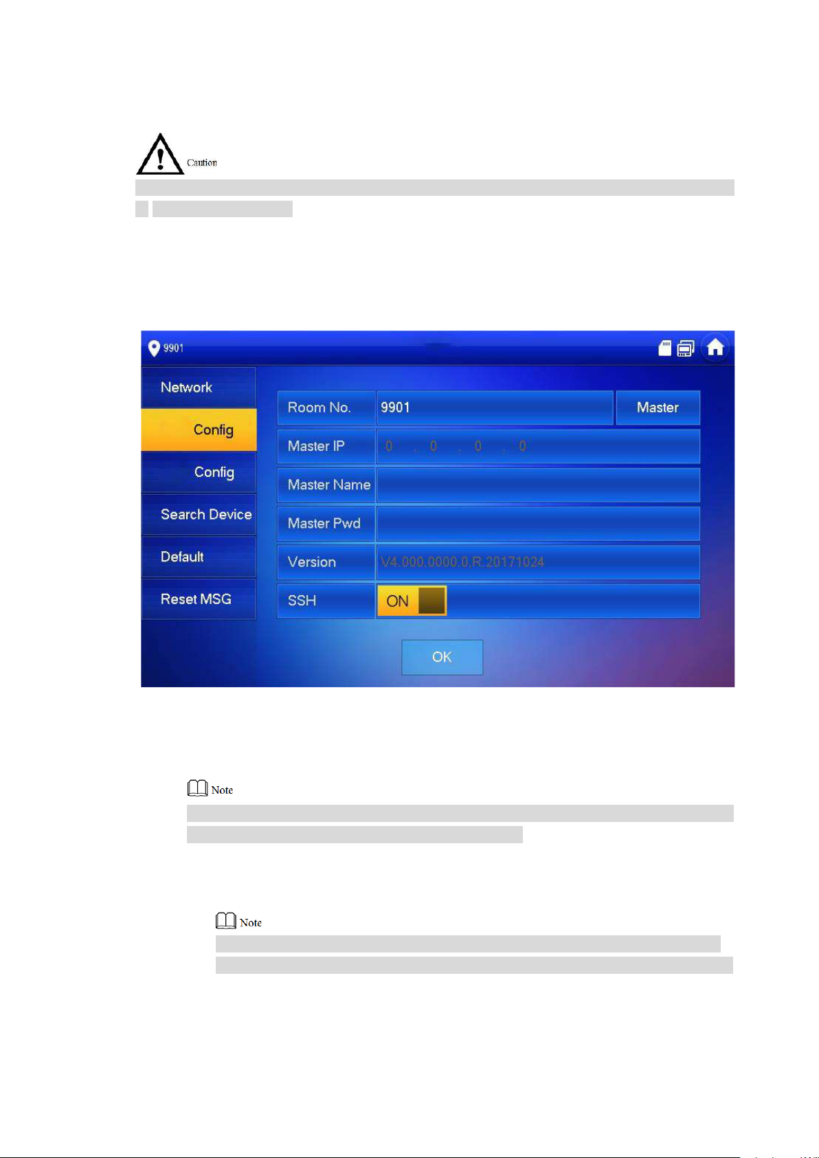
6.3.3
VUH Config
Configure VUH info.
VUH “Room No.” shall be the same with “VUH Short No.”, which is set at VUO WEB interface
or H500 platform server.
Step 1
Step 2
Step 3
Press [Setting] for over 6 sec onds.
The system pops up “Password” prompt box.
Enter the password set during i nitialization, and press [OK] .
Press [VUH Config].
The system displays “VUH Config” int erface, as shown in Figure 6-23.
Step 4 Set VUH info.
Be used as a master VUH.
nter “Room No.” (such as 9901).
E
“Room no.” shall be the same with “ VUH Shor t No. ”, which is set when adding VUH at
WEB interface. Otherw ise , it will fail to connect VUO.
Be used as an extension VUH.
1. Press [Master] and switch to “Extension”.
2. Enter “Room No.” (such as 9901-1) and “Mas t er I P” (IP address of master VUH).
“User Name” and “Passw ord” ar e the user name and password of ma st er VUH.
Default user name is admin, and the password is the one set duri ng initialization.
Step 5
Press [OK] to save settings.
Figure 6-23

53
6.3.4
VUO Config
Add VUO and fence st at ion info, and bind VUH with VUO on the VUH side.
Step 1
Step 2
Step 3
Press [Setting] for over 6 sec onds.
The system pops up “Password” prompt box.
Enter the password set during i nitialization, and press [OK] .
Press [VUO Config].
The system displays “VUO Config” int erface, as shown in Figure 6-24.
6.3.5
Figure 6-24
Step 4
Step 5
Enter main VUO/Sub VUO name, IP address, “User Name” and “Password”. Switch the
“Enable Status” to .
Press left and right arrows to switch VUO config tab.
Sub VUO shall select device type, which is “Door” by default. When fence station
is selected, configure VUO middle no. (which is VUO no.) and obtain IP address
automatically.
“User Name” and “Passw ord” s hall be the same as the user name and pas sword
to login VUO WEB. Otherwise, it will fail to connect.
Press [OK] to save settings.
Search Device
Search online devices in t he same network segment wit h VUH, add, modify IP and delete it.
After adding successful ly , this VUO can cal l VUH.
Support to modify IP addr ess of villa VUO, rather than IP address of unit VUO.
Step 1 Press [Setting] for over 6 seconds.

54
Step 2
Step 3
The system pops up “Password” prompt box.
Enter the password set during i nitialization, and press [OK] .
Press [Search Device].
The system displays “Sea r ch Device” interface, as shown in Fi gur e 6-25.
6.3.5.1 Search Device
Press [Refresh] to refresh device list; press to view t he device.
6.3.5.2 Modify IP
Step 1 Select the needed VUO and press [Modify I P] .
The system displays “Modify VUO IP” interface, as shown in Figur e 6-26.
If “Modify IP” is gray, it means that this dev ice is u nit VUO whose IP cannot be modified.
Figure 6-25

55
Step 2
Step 3
Fill in “Master IP”, “Netmask”, “Gateway”, “User Name” and “Password” of the VUO.
“User Name” and “Passw ord” ar e the user name and password to log in VUO WEB
interface.
Press [OK] to save the set t ings.
6.3.5.3 Add Manually
Figure 6-26
Step 1
Step 2
Select the needed VUO and press [A dd] .
The system displays “Add VUO” interface, as shown in Figur e 6-27.
Figure 6-27
Enter “Name”, “User Nam e” and “ Pa s sw or d” , and set “Status” to be “On”.
Step 3
“User Name” and “Passw ord” ar e the user name and password to log in VUO WEB
interface.
If it is a sub VUO, press to page down.
Press [OK] to complete configuration.

56
After successful configur ation, this VUO can call VUH.
6.3.5.4 Delete Device
Select a VUO that has been added, and press [delete] to delete it.
After deletion, this VUO info in WEB inter fa ce will be deleted too. In order t o use it again, this
VUO shall be added aga in .
6.3.6
6.3.7
Default
All parameters of the devi ce, exc ept I P address, can be restored to initial default values.
Step 1
Step 2
Step 3
Step 4
Press [Setting] for over 6 sec onds.
The system pops up “Password” prompt box.
Enter the password set during i nitialization, and press [OK] .
Press [Default].
The system displays “De f ault” int erface.
Press [OK].
The device reboots and enter s in it ia liz at ion interface, represent ing successful
restoration.
Reset MSG
Modify the bound Email.
Step 1
Step 2
Step 3
Press [Setting] for over 6 sec onds.
The system pops up “Password” prompt box.
Enter the password set during i nitialization, and press [OK] .
Press [Reset MSG].
The system displays “Res et M SG ” inter f ace, as shown in Figure 6-28.

57
6.4
Figure 6-28
Step 4
The Email will obtain security code during password resett ing. For details, please refer to “6.3.1
Forget Password”.
Call
Manage contact, call users and view the latest call log.
Enter “New Email” and pr ess [ OK].
6.4.1
Contact
Add and edit VUH and extension number.
Select “Call > Contact”, and t he system displays “Contact” interface, as shown in Figure 6-29.
Figure 6-29
6.4.1.1 Add User
Step 1 Press [Add].
The system displays “Use r I nfo” interface, as shown in Figure 6-30.

58
Step 2
Step 3
Enter “Last Name”, “First Na m e” and “ R oom No.” of contact person.
Press [Save] to complete adding.
6.4.1.2 Edit Contact Info
Select the contact person, pr es s to edit the info.
6.4.1.3 Delete Contact Person
Press [Edit], select the contact person and press [Delete] t o delete the contact person.
Multiple contact persons c an be selected once.
Figure 6-30
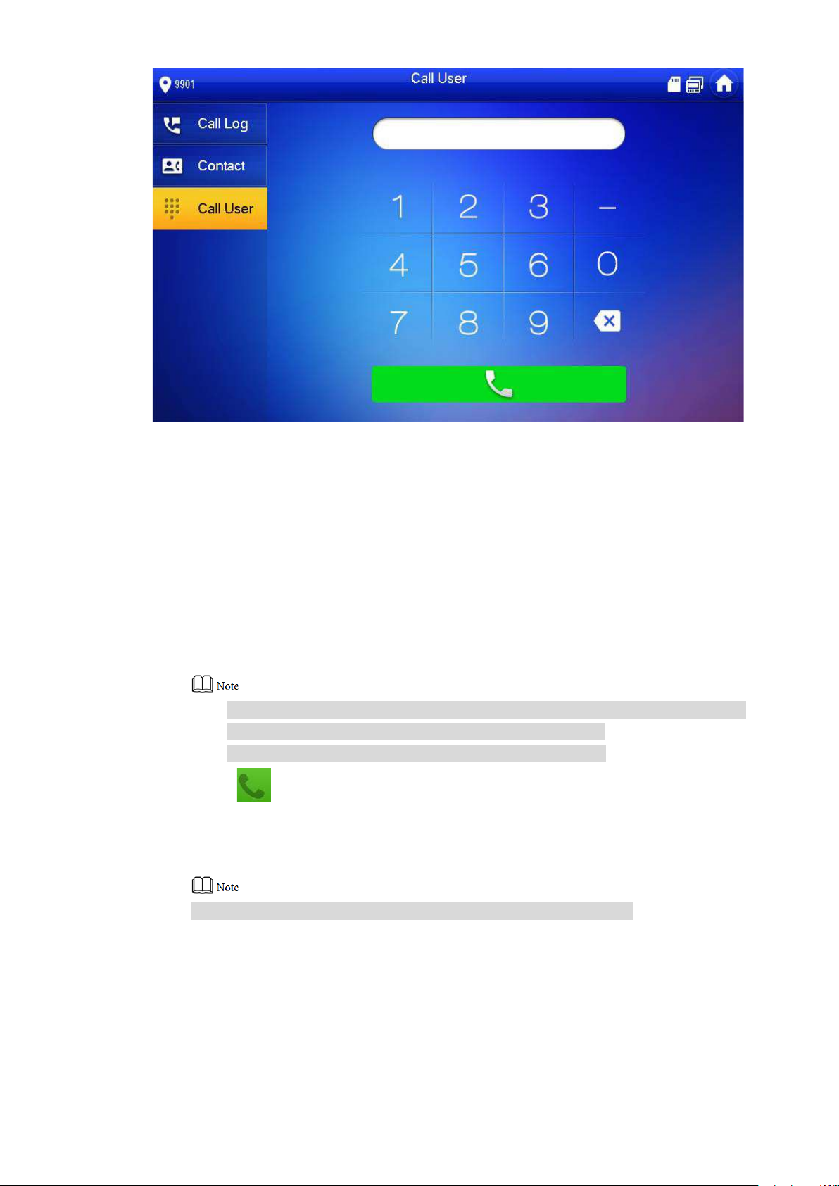
6.4.2
Call User
Make sure that internal call function has been enabled. Pl ease r efer to “6.2.5.4 Other
Settings” for details.
Call function is used by VUH to call VUH.
If both VUHs have a camera, bilateral v ideo call can be provided.
6.4.2.1 Dial and Call User directly
At “Call User” interface, dial and call the user.
Step 1 Select “Call > Call User”.
The system displays “Ca ll User ” interface, as shown in Figure 6-31.
59
Step 2
Figure 6-31
Enter the user’s room no. (VUH room no.).
In case of continuous diali ng rule,
◇ Call a user in the same building, dial 4-digit room number directly.
◇ Call a user in other buildings, add the buil di ng number. For example, dial
1-9901 to call Building 1 Room 9901.
In case of discontinuous dial in g rule,
◇ Call a user in the same building and the sa me un it , dial 4-digit room number
directly.
◇ Call a user in other buildings or other un its, add the building number and un it
number. For example, dial 1-1-9901 to call Building 1 Unit 1 Room 9901.
If master VUH (9901) calls extension (9901-1), plea se ent er r oom no.: -1; if the
extension calls master VUH, please enter r oom no.: 9901.
Dialing rule is set in “Product I nfo” at VUO WEB interface.
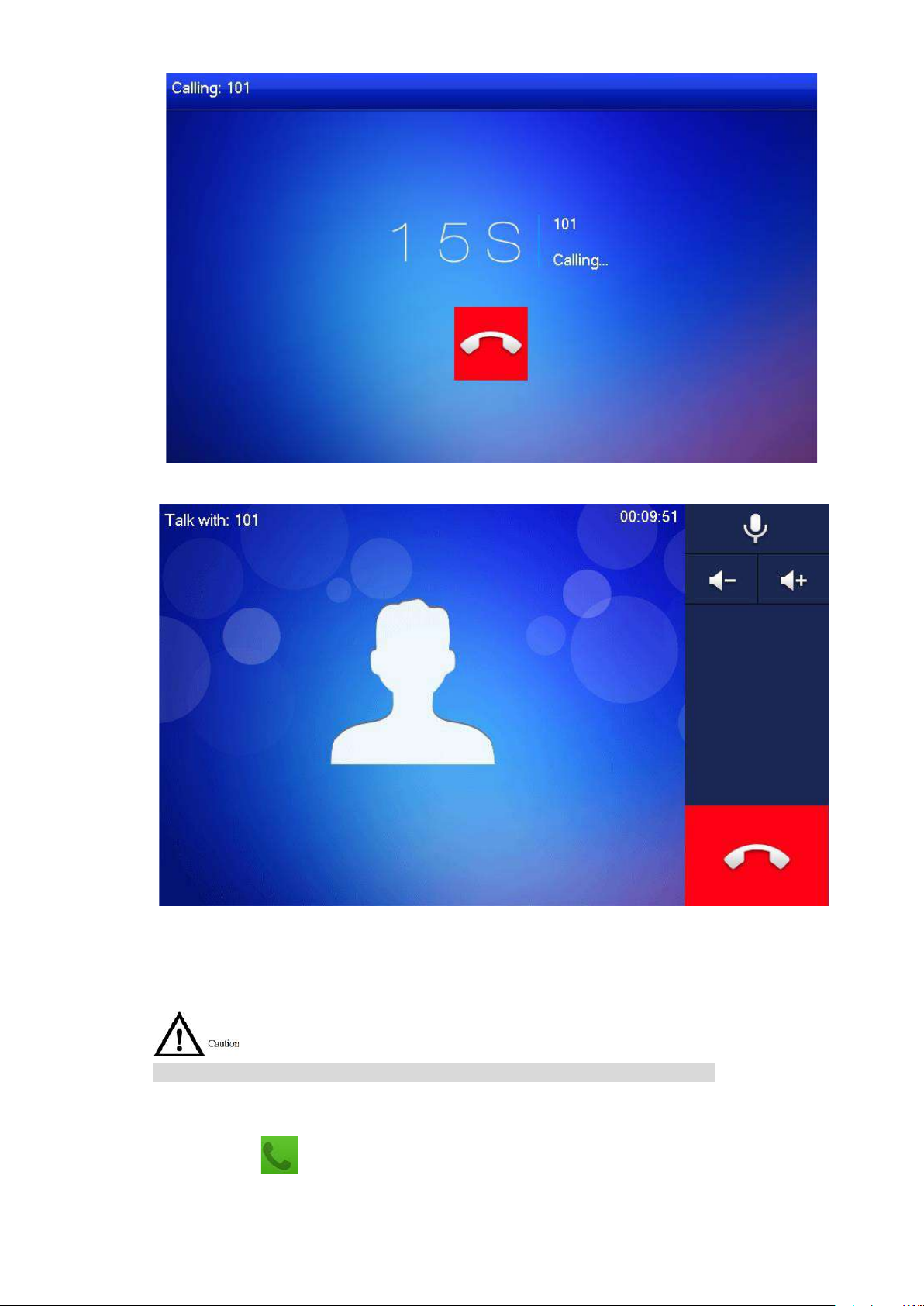
Step 3
Press to start.
The system displays calling interface, as shown in Figure 6-32. After the user answers
the call, both parties talk to each other, as shown in Figure 6-33. For interface key
description, please refer t o Table 6-4.
If VUH owns a camera, there will be videos after answering the call.
60
Figure 6-32
Figure 6-33
6.4.2.2 Call User in Contact
Please add contact persons t o t he cont act, by reference to “6.4.1.1 Add User”.
Step 1
Step 2
Step 3
Select “Call > Contact” .
Select the one you want to call.
Press to start.

61
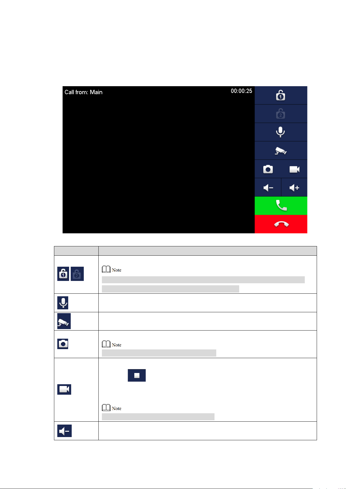
6.4.3 Call from User
When another VUH calls this VUH, the call interface will be displayed, as shown in Figure 6-34.
Figure 6-34
Press to talk with each other, as shown in Figure 6-35. For key description, pleas e
refer to Table 6-4.
Press to hang up.
Figure 6-35
62
6.4.4 Call from VUO
Key
Description
Press this key to unlock th e VUO remotely.
This key means to talk with the opposite end device.
Press this key to snapshot.
Step 1
Step 2
Dial VUH room no. (such as 9901) at VUO, to call VUH.
VUH pops up a waiting picture, as shown in Figure 6-36.
At VUH interface, press [Answer] .
Answer the call and talk with eac h other. For key description, pl ease refer to Table 6-4.
Figure 6-36
/
The system provides 2-ch annel unlock function. If the icon is gray, it means
that unlock function of this channel is not available.
Press this key to prohibit tal king; pr ess it again to switch back to talki ng st atus.
Press this key to select IPC that shall be monitored.
This key is gray if SD card is not inst alled.
Press this key to record. Com plet e recording when the call is com pleted or by
pressing .
Videos are stored in SD card of this VUH. If SD card is full, the earlier video s
will be covered.
This key is gray if SD card is not inst alled.
Press this key to reduce volu me.

63
Key
Description
6.4.5 Call Log
In case of missed call, press on the front panel and enter call log interface.
View and manage the missed call, accepted call and called log o f this VUH. Meanwhile, call
back and save info about the contact persons.
Select “Call > Call Log”, and the system displays “Call Log” inter fa ce, as shown in Figure 6-37.
If contact person is VUO, callback is not available.
Press this key to increase volume.
Press this key to answer and talk.
Press this key to refuse.
Table 6-4
Figure 6-37
6.4.5.1 Callback
Select the required VUH log, press [ C all] to call the contact person.
6.4.5.2 Delete
Press [Edit], select a log and press [Delete] to delete it.

64
6.4.5.3 Clear
Press [Clear] to clear all lo gs in this tab.
6.5
Monitor
VUH is able to monitor VUO, fence station or IP C.
6.5.1
Monitoring of VUO
Please confirm user name and password in VUH, which are set when adding VUO. They shall
be consistent with WEB login user name and password of VUO. Otherwise, it will fail to obtain
videos during monitoring.
VUH is able to monitor VUO or fence station. U nder the condition of monitoring, pr ess call key
on the front panel to talk to VUO. VUO will pick up the call automatically.
Step 1
Select “Monitor> VUO”.
The system displays the list of added VUO and fence station, as shown in Figure 6-38.
Press to add frequently-used VUO or fence station to favorites, w hich will be
displayed in “Favorite” tab , so as to switch videos during monitoring.
Step 2
Figure 6-38
Press to select VUO that shall be monitored.
The device enters monitor ing, as s hown in Figure 6-39. For relevant monitoring

65
operations, please refer t o Tabl e 6-5.
Icon
Description
Press this key to record. Com plet e recording when the call is com pleted
Speak to VUO directly after succes sf ul mo nit oring.
Figure 6-39
Press this key to unlock VUO remotely.
/
/
The system provides 2-ch annel unlock function. If the icon is gray, it
means that unlock function of this channel is not availab le.
Press this key to snapshot.
This key is gray if SD card is not inst alled.
or by pressing .
Videos are stored in SD card of this VUH. If SD card is full, the earlier
videos will be covered.
This key is gray if SD card is not inst alled.
If VUH connects multiple VUO/IPC, press
last/next channel.
and
to switch to
Press this key to cancel m onitoring.
Press this key to speak to t he ot her end device.
Press this key to start and the icon becomes
complete.
Table 6-5
. Press it again to

66
6.5.2
Monitoring of IPC
Please add IPC before monitoring of IPC.
6.5.2.1 Add IPC
IPC added at main VUO and H500 “IPC” interface will be sy nchr onized to VUH. The
synchronized IPC cannot be deleted.
Before adding IPC, please ensur e t hat IPC has been powered on, and con nected to the
same network with VUH.
Step 1 Select “Monitor> IPC”.
The system displays “IPC” interface, as shown in Figure 6-40. Press to add
frequently-used IPC to favorites, which will be displayed in “Favorite” tab, so as to
switch videos during monitoring.
Figure 6-40
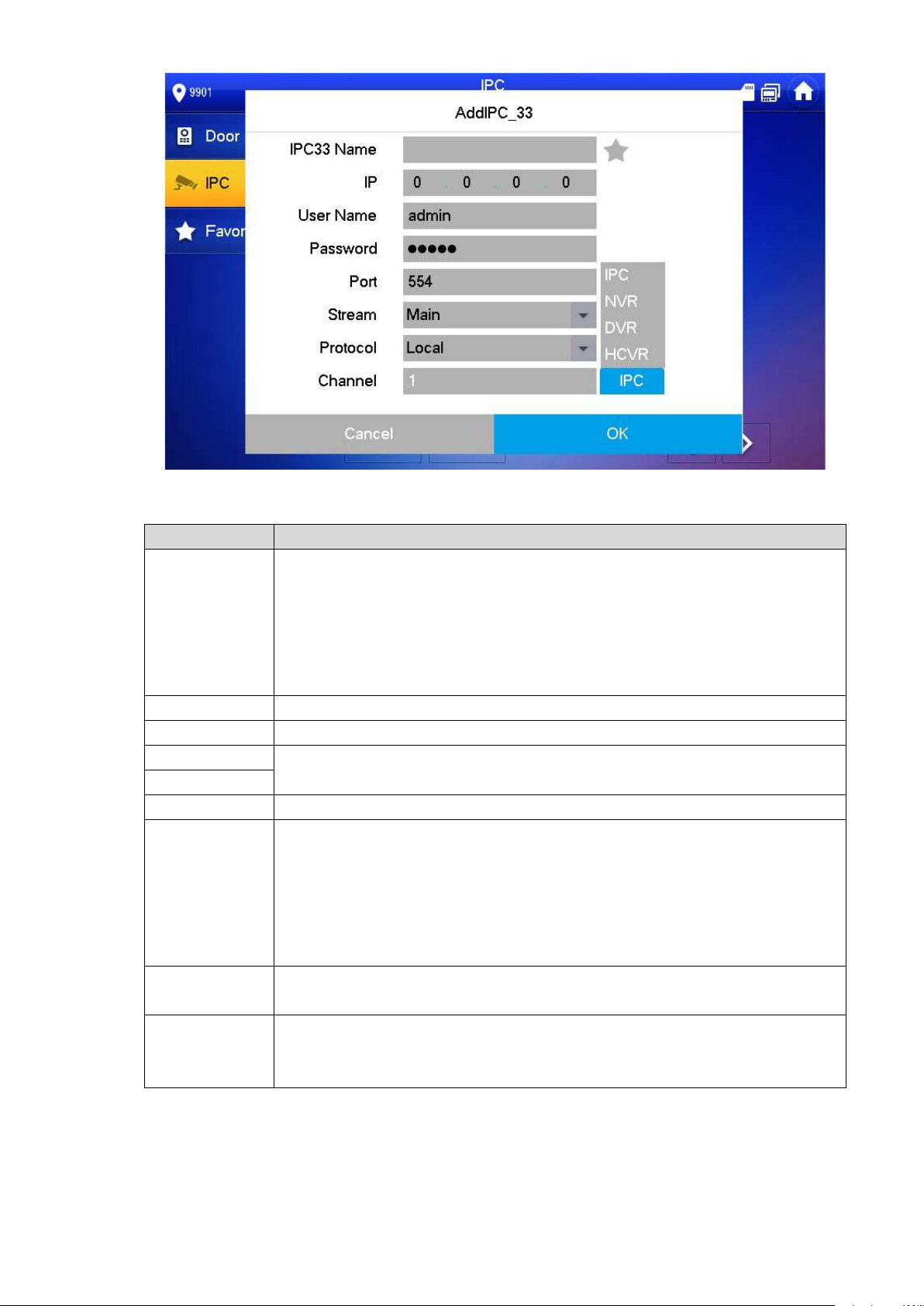
Step 2 Press [Add].
The system displays “Add I PC” interface, as shown in Figure 6-41.
67
Figure 6-41
Parameter
Description
Press this key to select IPC, N VR, DVR and DVR.
Port
Default port is 554.
Select stream type accord ing to needs, including main strea m an d ext r a
It includes local protocol a nd O nvif protocol. Please select accor ding to the
Step 3
IPC
Please refer to Table 6-6 to configure camera paramet er s.
Select IPC, meaning that VUH obt ai ns video stream from the connect ed
IP
C directly. It is necessary to configure IPC info.
Select NVR/DVR/DVR, meaning that VUH obtains IPC video stream
from the connected device. It is necessary to configure info about t
c
onnected device.
IPC33 Name Input IPC/ NVR/DVR/DVR name.
IP Input IP address of the connect ed IPC/NVR/DVR/DVR.
User Name
Password
Input user name
IPC/NVR/DVR/DVR.
and password to login WEB interface of
stream.
Stream
Main stream: large stream, high definition, large occ upied bandwidth,
suitable for local storage.
Extra stream: relatively smooth image, small occupied bandwidth,
suitable for network trans mission with low bandwidth.
he
Protocol
protocol of the connected device.
If IPC is connected, defau l t s et t ing is 1.
Channel
If NVR/UVR/DVR is connected, set channel number of IPC on
NVR/UVR/DVR.
Table 6-6
Step 4 Press [OK] to finish.
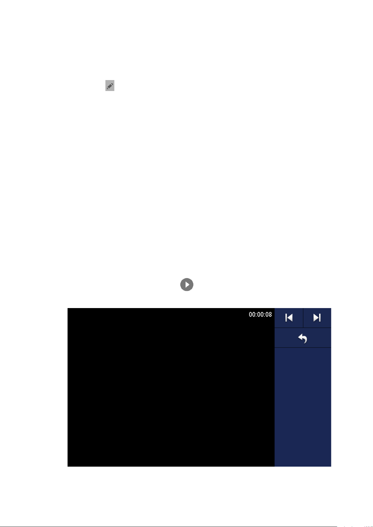
68
6.5.2.2 Modify IPC
Modify IPC info.
Step 1
Select “Monitor> IPC”.
The system displays “IPC” interface.
Step 2
Step 3
Step 4
Press of IPC.
Modify IPC parameters. P l eas e r efer to Table 6-6 for details.
Press [OK] to finish.
6.5.2.3 Delete IPC
Delete IPC that has been added. However, IPC synchronized from VUO or the platform cannot
be deleted.
Step 1
Step 2
Step 3
Step 4
Select “Monitor> IPC”.
The system displays “IPC” interface.
Press [Edit].
Select IPC.
Press [Delete] to delete th e sele cted IPC.
6.5.2.4 Monitor IPC
Monitor the IPC.
Step 1
Select “Monitor> IPC”.
The system displays “IPC” interface.
Step 2
Select IPC to be monitore d, and .
The system displays moni t or ing interface, as shown in Figure 6-42.
Step 3
Figure 6-42
Please monitor the VUO by reference to Table 6-5.
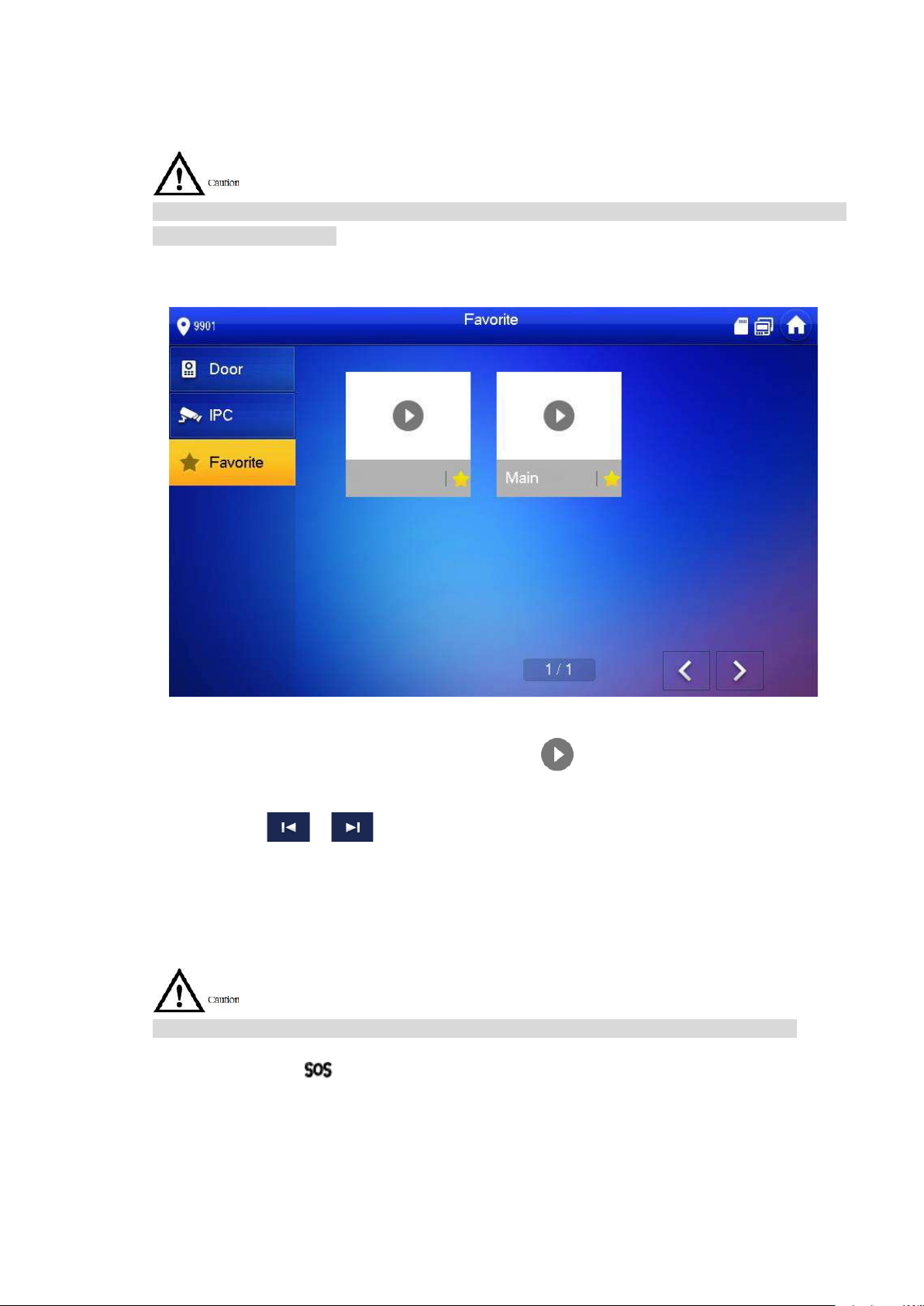
69
6.5.3 Favorite
Display VUO, fence stations or IPC that have been adde d t o fav or it es.
To view favorite list, please ensure that VUO, fence station or IPC have been added to favorites.
Otherwise, the list is null.
Step 1
Select “Monitor> Favorite”.
The system displays “Fav or it e” interface, as shown in Figure 6-43.
6.6
Figure 6-43
Step 2
SOS
Please ensure that managem ent center has been connected. Otherwise, it will fail to call.
In emergency, press but t on on t he front panel, or press [SOS] at t he main interface to call
management center.
Select the device to be monitore d, and press .
The system displays moni t or ing interface. In case of multiple devices in “Favorite” tab,
press / to switch and monitor them.

70
6.7
Info
6.7.1
Alarm
All alarm info is stored in the device.
When an alarm is triggered, there will be 15s alarm sound. Pop up alarm prompt interface, as
shown in Figure 6-44, and upload the alarm info to alarm record interface and management
platform.
Figure 6-44
Alternatively, select “Info > Alarm”, and the system displays “Alarm” interface, as shown in
Figure 6-45. “All” tab displays all alarm info of the system, whereas “Unread” tab displays
unread alarm info.
Press [Edit] to select the info; pr ess [Delete] to delete the sel ect ed info.
Press [Clear] to delete all rec or ds after confirmation.

71
Figure 6-45
6.7.2
Guest Message
When a SD card is inserted int o t he device, this function is valid. A ll me s sages are stored
in SD card.
If SD card is not inserted, but VUO WEB has set FTP and sele ct ed “ Video-audio Message
Uploading”, this function is valid too. All messages will be up loa ded t o FTP.
Select “Info > Guest Message”, and the system displays “Guest Message” interface, as shown
in Figure 6-46. “All” tab displays all messages of the system, whereas “Unread” tab displays
unread messages.
Press [Edit] to select the info; pr ess [Delete] to delete the sel ect ed info.
Press [Clear] to delete all mes sages after confirmation.

72
Figure 6-46
6.7.3
Publish Info
Info released by the management center is stored in the dev ice, and pictures, if any, are stored
in SD card.
Select “Info > Publish Info” , and t he s ystem displays “Publish Info” inter f ac e, as shown in Figure
6-47. “All” tab displays all info of the system, whereas “Unread” tab displays unread info.
Press [Edit] to select the info; pr ess [Delete] to delete the sel ect ed info.
Press [Clear] to delete all i nfo a ft er confirmation.
Figure 6-47

73
6.7.4
Video Pic
When a SD card is inserted int o t he device, this function is valid. A ll v ide os and pictures are
stored in SD card.
Select “Info > Video Pic”, and the system displays “Video Pic” interface, as shown in Figure 6-
48.
Press [Edit] to select the vide o or pictur e; pr ess [Delete] to delete the select ed video or
picture.
Press [Clear] to delete all videos and pictures after confirmation.
6.8
6.9
6.9.1
Figure 6-48
Unlock Function
When the VUH is being called, during mo nitoring, talking and speaking, press exit button, and
the VUO will be unlock ed remotely.
Arm and Disarm Function
Arm
In case of triggering alarm after arm, produce linkage alarm and upload alarm info.
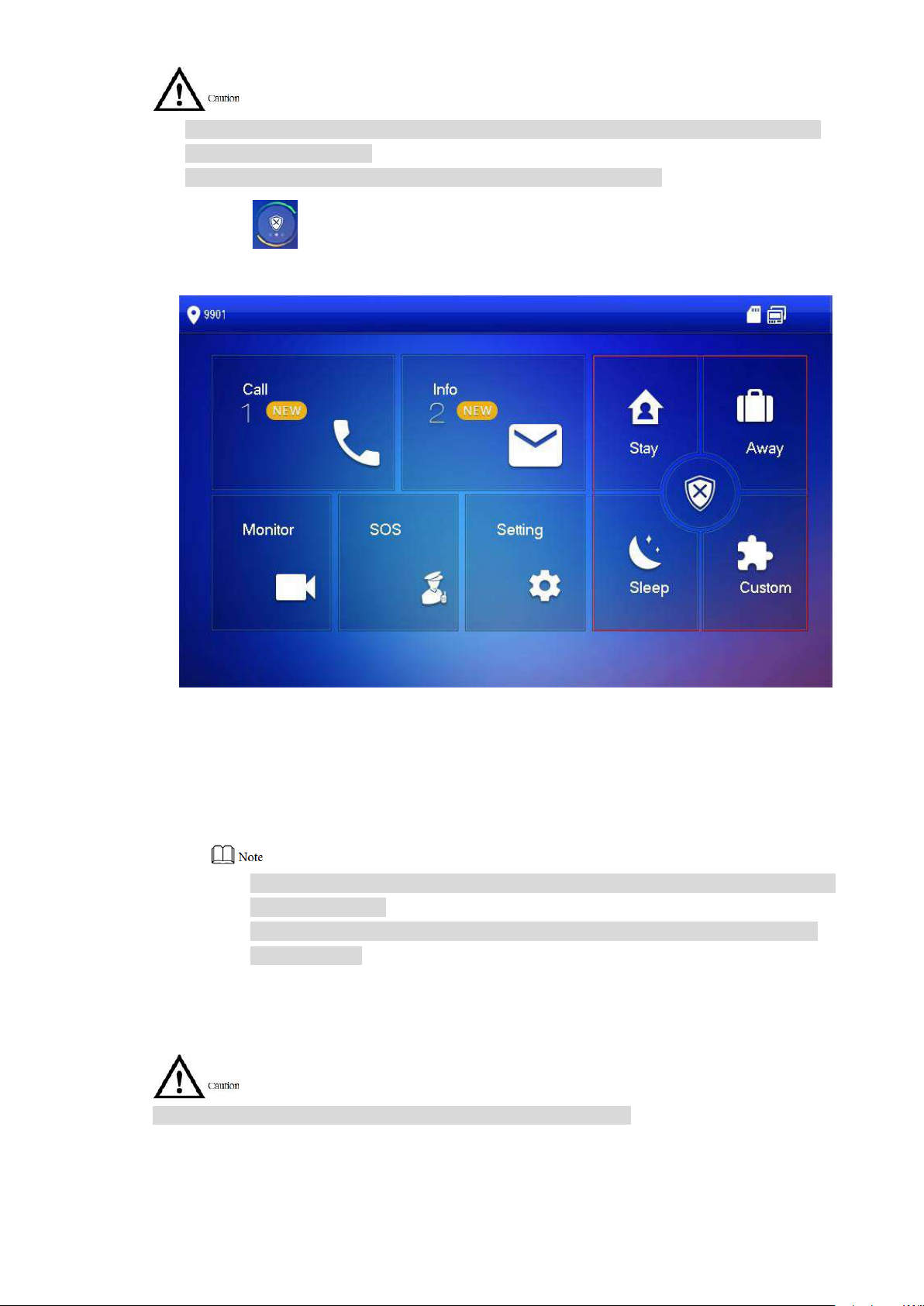
74
Please ensure that the area has been added into arm mode. Ot her w ise, t her e will be no
alarm triggering after arm.
Please ensure that it is in disar m ed st atus. Otherwise, arm will fail.
Step 1 Press at the main interface.
The system displays arm mo de, as shown in Figure 6-49.
6.9.2
Figure 6-49
Step 2 Select arm mode.
The system displays pass w or d input interface.
Step 3
Enter arm and disarm passw or d; pr ess [ O K] .
The device beeps continuously, which represents s uc cessful arm. The key displays
corresponding arm mode.
Default password of arm and disarm is 123456. Please refer to “6.2.5.3 Password
Setting” for details.
If delay alarm is set in the area, t he device will beep continuously at the end of
exit delay time.
Disarm
Please ensure that it is in armed status. Otherwise, disarm wi ll fail.
Step 1
Step 2
Press disarm symbol at the lower r ig ht corner of the main interface.
The system displays pass w or d input interface.
Enter arm and disarm passw or d; pr ess [ O K] .

75
The system displays succ essful disarm.
Default password of arm and disarm is 123456. Please refer to “6.2.5.3 Password
Setting” for details.
If you are forced to enter disarm password in case of emergencies, enter anti-
hijacking password, which is the reversed arm password. The sys t em will dis arm,
and at the same time, upload alarm info to management center/platform.

76
Appendix 1 Technical Parameters
Model
VUH5221D
VUH5241DW
Main Processor
Embedded CPU
Display
7″ HD LCD 1024×600
10″ HD LCD 1024×600
Talk
Support two-way audio tal k
Input
Omnidirectional micropho ne
Input
Capacitance touch and 5 shor t cut keys
Alarm Output
1-channel
Material
PC+ABS
Installation
Installation with 86 box in t he w all
Ethernet
10M/100Mbps self-adapt ive; Support WI-FI 802.11b/ g/n
Power Supply
DC 12V-24V or designated switch
Working Temperature
Relative Humidity
10% RH~90%RH
Model
VUH5222CH
Operating System
Embedded LINUX Operati ng System
Video Compression
Video Resolution
800×480
Display
Screen Size
7″ TFT color screen
Appendix 1.1 VUH5221D Series /VUH5241DW Series
System
Video
Audio
Operating
Mode
Structure
Network
Parameter
Operating System Embedded LINUX Operating System
Camera (Type C) 1 megapixel CMOS HD camera
Audio Enhancement Echo suppression and dig it al no ise reduction
Alarm Input 6-channel
Network Protocol TCP/IP
Power Consumption Standby ≤1W; working ≤8W
﹣10℃~+55℃
Size (Length× Width ×
Height)
215mm×140mm×16mm 265mm×180mm×22mm
Appendix 1.2 VUH5222CH Series
System
Video
Audio
Main Processor Embedded microcontroller
Standard
Front Camera None
Input Omnidirectional micropho ne
Output Built-in speaker
Talk Support two-way audio tal k
H.264

77
Operating
Mode
Mechanical key (SOS, menu, call, monitor and
Alarm Input
Support 6-channel alar m input
Alarm Output
Support 1-channel alar m output ( dr y contact)
Ethernet
10M/100Mbps self-adaptive
Network Protocol
TCP/IP
Wi-Fi
Not available
Power Supply
Direct power supply from pr ivate exchange
Power Consumption
Standby ≤1.5W; working ≤7W
Size (Length× Width ×
Weight
0.8kg
VUH15 Series Type
B(W)
VUH15 Series Type
CH
Processor
Operating
Video
Video
Front
Display
Screen Size
7″ TFT color screen
Operating
Mechanical key (SOS, menu, call, monitor and unlock), t ouch screen
Ethernet
10M/100Mbps self-adaptive
Network
Power
Alarm
Network
Input
unlock), touch screen tec hnology
-10℃~+55℃
10%RH~90%RH
200mm×136mm×22mm
Parameter
Working Environment
Height)
Appendix 1.3 VUH15 Series Type A/B/CH
Model VUH15 Series Type A
Main
System
System
Compressio
n Standard
Video
Resolution
Embedded microcontroller
Embedded LINUX Operati ng System
H.264
800×480
Camera
Input Omnid irect ion al micropho ne
Audio
Mode
Alarm
Network
Paramete
r
Output Built-in speaker
Talk Support two-way audio talk
Input
Alarm
Input/output
Protocol
Supply
Power
Consumptio
Only VUH1520CH supports front Camera, 300,000 pixels
technology
For VUH15 series type A/type B and VUH1550 CHM ,alar m in/out: 8/0;
For VUH15 series type CH, alarm in/out: 6/1.
TCP/IP
DC10V – 15V or direct power supply from private exchange
Standby≤1.5W; working≤7W

78
n
Working
Environment
-10
+55
Size
Weight
0.8kg
Model
VUH1660CH
Main Processor
Embedded microcontroller
Operating System
Embedded LINUX Operati ng System
Video Compression
Video Resolution
800×480
Front Camera
None
Input
Omnidirectional micropho ne
Output
Built-in speaker
Talk
Support two-way audio tal k
Display
Screen Size
10.2″TFT color screen
Operating
Alarm Input
6-channel
Alarm Output
1-channel
Ethernet
10M/100Mbps self-adaptive
Network Protocol
TCP/IP
DC10V – 15V or direct power supply from private
Power Consumption
Standby≤1.5W; working≤7W
-10
+55
10%RH~90%RH
Size (Length× Width ×
Weight
0.8Kg
Model
VUH2221A
Main Processor
Embedded microcontroller
Operating System
Embedded LINUX Operati ng System
℃~
10%RH~90%RH
℃
(Length×
Width ×
Height)
221mm×154mm×25m m 221mm×154mm×25m m 200mm×136mm×22m
Appendix 1.4 VUH16 S er i es
System
Video
Standard
Audio
H.264
m
Mode
Alarm
Network
Parameter
Input Touch screen technology
Power Supply
Working Environment
Height)
exchange
℃~
260mm×189mm×22.7mm
Appendix 1.5 VUH2221A Series
℃
System

79
Model
VUH2221A
Video
Video
Video Resolution
800×480
Front Camera
None
Input
Omnidirectional micropho ne
Output
Built-in speaker
Talk
Support two-way audio tal k
Display
Screen Size
7″ TFT color screen
Operating
Mechanical key (SOS, menu, call, monitor and unlock),
Alarm Input
Support 6-channel loca l alar m input
Alarm Output
Reserve 1-channel local a larm output
Ethernet
10M/100Mbps self-adaptive
Network Protocol
TCP/IP
Power Supply
DC10V – 15V or direct power supply from private exchange
Power
10%RH~90%RH
Size (Length×
Weight
0.8kg
Audio
Compression
Standard
H.264
Mode
Alarm
Network
Parameter
Input
Consumption
Working
Environment
Width × Height)
touch screen technology
Standby ≤1.5W; working ≤7W
-10℃~+55℃
220mm×153mm×22.5mm
 Loading...