

Inaxsys STORM INS88NVR1T, STORM INS44NVR1T, STORM INS88NVR series, STORM INS44NVR series User Manual

Network Video Recorder User’s Manual
V 2.0.0

Table of Contents
1 Features and Specifications ..................................................................................................... 1
1.1 Overview ............................................................................................................................ 1
1.2 Features ............................................................................................................................. 1
1.2.1 INS44NVR1T and INS88NVR1T ................................................................................ 3
1.2.2 INS44NVR / INS88NVR Series ................................................................................... 5
1.3 Alarm Connection .............................................................................................................. 6
1.3.1 Alarm Port ................................................................................................................... 6
1.3.2 Alarm Input Port .......................................................................................................... 7
1.3.3 Alarm Input and Output Port ....................................................................................... 8
1.3.4 Alarm Relay Specifications ......................................................................................... 8
1.4 Bidirectional Audio/Talk ..................................................................................................... 9
1.4.1 Device-end to PC-end ................................................................................................. 9
1.4.2 PC-end to the device-end ........................................................................................... 9
1.5 Mouse Operation ............................................................................................................. 10
2 Device Installation ................................................................................................................... 12
2.1 Check Unpacked NVR .................................................................................................... 12
2.2 About Front Panel and Rear Panel ................................................................................. 12
2.3 HDD Installation ............................................................................................................... 12
2.3.1 INS44NVR / INS88NVR/11HS Series ....................................................................... 12
2.4 Connection Sample ......................................................................................................... 14
2.4.1 INS44NVR / INS88NVR Series ................................................................................. 14
3 Local Basic Operation ............................................................................................................. 15
3.1 Boot up and Shutdown .................................................................................................... 15
3.1.1 Boot up ...................................................................................................................... 15
3.1.2 Shutdown .................................................................................................................. 15
3.2 Startup Wizard ................................................................................................................. 16
3.3 Navigation Bar ................................................................................................................. 19
3.3.1 Main Menu ................................................................................................................. 20
3.3.2 Dual-Screen Operation ............................................................................................. 20
3.3.3 Output Screen ........................................................................................................... 20
3.3.4 Tour ............................................................................................................................ 21
3.3.5 PTZ ............................................................................................................................ 21
3.3.6 Color .......................................................................................................................... 21
3.3.7 Search ....................................................................................................................... 21
3.3.8 Alarm Status .............................................................................................................. 21
3.3.9 Channel Info .............................................................................................................. 21
3.3.10 Remote Device ...................................................................................................... 22
3.3.11 Network ................................................................................................................. 22
3.3.12 HDD Manager ....................................................................................................... 22
3.3.13 USB Manager ........................................................................................................ 22
3.4 Smart Add ........................................................................................................................ 22
3.5 Remote Device ................................................................................................................ 26
3.5.1 Remote Device Connection ...................................................................................... 26
i

3.5.2 Shortcut Menu ........................................................................................................... 27
3.5.3 Image ......................................................................................................................... 28
3.5.4 Channel Name .......................................................................................................... 30
3.5.5 Upgrade ..................................................................................................................... 31
3.5.6 UPNP ......................................................................................................................... 32
3.5.7 Built-in Switch Setup ................................................................................................. 32
3.6 Preview ............................................................................................................................ 33
3.6.1 Preview ...................................................................................................................... 33
3.6.2 Preview Control Interface .......................................................................................... 34
3.6.3 Right Click Menu ....................................................................................................... 36
3.6.4 Preview Display Effects Setup .................................................................................. 37
3.6.4.1 Video Color ....................................................................................................... 37
3.6.4.2 Display .............................................................................................................. 39
3.6.4.3 TV Adjust ........................................................................................................... 40
3.6.5 Preview Tour Parameters .......................................................................................... 40
3.7 PTZ .................................................................................................................................. 42
3.7.1 PTZ Settings .............................................................................................................. 42
3.7.2 PTZ Control ............................................................................................................... 44
3.7.2.1 PTZ Function Setup .......................................................................................... 46
3.7.2.2 Call PTZ Function ............................................................................................. 48
3.8 Record and Snapshot ...................................................................................................... 50
3.8.1 Encode ...................................................................................................................... 50
3.8.1.1 Encode .............................................................................................................. 50
3.8.1.2 Overlay .............................................................................................................. 51
3.8.1.3 Snapshot ........................................................................................................... 52
3.8.2 Schedule ................................................................................................................... 53
3.8.2.1 Recording Schedule.......................................................................................... 53
3.8.2.2 Snapshot Schedule ........................................................................................... 57
3.8.3 Motion Detect Recording/Snapshot .......................................................................... 59
3.8.3.1 Motion Detect Recording .................................................................................. 59
3.8.3.2 Motion Detection Snapshot ............................................................................... 62
3.8.4 Alarm Recording/Snapshot ....................................................................................... 63
3.8.4.1 Alarm Recording ............................................................................................... 63
3.8.4.2 Alarm Snapshot ................................................................................................ 65
3.8.5 Manual Record/Snapshot .......................................................................................... 65
3.8.5.1 Manual Recording ............................................................................................. 65
3.8.5.2 Manual Snapshot .............................................................................................. 67
3.8.6 Holiday Record/Snapshot ......................................................................................... 67
3.8.6.1 Holiday Record ................................................................................................. 67
3.8.6.2 Holiday Snapshot .............................................................................................. 69
3.8.7 Other Record/Snapshot ............................................................................................ 69
3.9 Playback and Search ...................................................................................................... 69
3.9.1 Real-Time Playback .................................................................................................. 69
3.9.2 Search Interface ........................................................................................................ 69
3.9.2.1 Smart Search .................................................................................................... 75
3.9.2.2 Accurate Playback by Time .............................................................................. 75
ii

3.9.2.3 Mark Playback .................................................................................................. 76
3.9.3 Picture Playback........................................................................................................ 78
3.10 Backup ............................................................................................................................. 78
3.10.1 File Backup ........................................................................................................... 78
3.10.2 Import/Export ......................................................................................................... 80
3.10.3 Backup Log ........................................................................................................... 82
3.10.4 USB Device Auto Pop-up ...................................................................................... 82
3.11 Alarm ............................................................................................................................... 83
3.11.1 Detect Alarm .......................................................................................................... 83
3.11.1.1 Motion Detection ............................................................................................... 83
3.11.1.2 Tampering ......................................................................................................... 88
3.11.1.3 Video Loss ........................................................................................................ 89
3.11.2 Alarm Output ......................................................................................................... 90
3.11.3 Alarm Setup .......................................................................................................... 91
3.11.4 Abnormality ........................................................................................................... 97
3.12 Network ............................................................................................................................ 99
3.12.1.1 TCP/IP ............................................................................................................... 99
3.12.1.2 Connection .......................................................................................................... 102
3.12.1.3 WIFI AP ............................................................................................................... 103
3.12.1.4 WIFI ..................................................................................................................... 104
3.12.1.5 3G ................................................................................................................... 105
3.12.1.6 PPPoE ............................................................................................................. 107
3.12.1.7 DDNS Setup ................................................................................................... 108
3.12.1.8 UPnP ............................................................................................................... 110
3.12.1.9 IP Filter ............................................................................................................ 112
3.12.1.10 Email .............................................................................................................. 114
3.12.1.11 FTP ................................................................................................................. 115
3.12.1.12 SNMP ............................................................................................................. 117
3.12.1.13 Multicast ......................................................................................................... 119
3.12.1.14 Alarm Center .................................................................................................. 120
3.12.1.15 Auto Register ................................................................................................. 121
3.12.1.16 P2P ................................................................................................................. 122
3.12.1.17 Easy Space .................................................................................................... 122
3.12.1.18 SWITCH ......................................................................................................... 123
3.12.2 Network Test........................................................................................................ 124
3.12.2.1 Network Test ................................................................................................... 124
3.12.2.2 Network Load .................................................................................................. 125
3.13 HDD Setup .................................................................................................................... 126
3.13.1 Format ................................................................................................................. 126
3.13.2 HDD Information ................................................................................................. 127
3.13.3 Advanced ............................................................................................................ 129
3.13.4 HDD Detect ......................................................................................................... 132
3.13.4.1 Manual Detect ................................................................................................. 132
3.13.4.2 Detect Report .................................................................................................. 133
3.13.5 RAID Manager .................................................................................................... 135
3.13.5.1 RAID Config .................................................................................................... 135
iii

3.13.5.2 Hot spare Disks ............................................................................................... 135
3.14 Basic Setups .................................................................................................................. 136
3.14.1 Device Setup ....................................................................................................... 136
3.14.2 Date and Time ..................................................................................................... 138
3.14.3 Holiday ................................................................................................................ 139
3.15 Device Maintenance and Manager ............................................................................... 139
3.15.1 System Info ......................................................................................................... 139
3.15.1.1 Version ............................................................................................................ 139
3.15.1.2 BPS ................................................................................................................. 140
3.15.1.3 Online Users ................................................................................................... 140
3.15.1.4 Remote Device Information ............................................................................ 141
3.15.1.5 Remote ............................................................................................................ 142
3.15.1.5.1 Device Status .............................................................................................. 142
3.15.1.5.2 Firmware ..................................................................................................... 142
3.15.2 Log ...................................................................................................................... 143
3.15.3 Voice .................................................................................................................... 144
3.15.3.1.1 File Manage ................................................................................................ 145
3.15.3.1.2 Schedule ..................................................................................................... 146
3.15.4 Account ............................................................................................................... 147
3.15.4.1 Add/Modify Group ........................................................................................... 149
3.15.4.2 Add/Modify User ............................................................................................. 150
3.15.5 Update ................................................................................................................. 150
3.15.6 Default ................................................................................................................. 151
3.15.7 RS232 ................................................................................................................. 152
3.15.8 Auto Maintain ...................................................................................................... 153
3.15.9 Logout/Shutdown/Restart ................................................................................... 154
4 Web Operation ...................................................................................................................... 155
4.1 General Introduction ...................................................................................................... 155
4.1.1 Preparation .............................................................................................................. 155
4.1.2 Log in ....................................................................................................................... 156
4.2 LAN Mode ...................................................................................................................... 158
4.3 Real-Time Monitoring .................................................................................................... 161
4.4 PTZ ................................................................................................................................ 161
4.5 Image/Alarm Out ........................................................................................................... 163
4.5.1 Image ....................................................................................................................... 163
4.5.2 Alarm Output ........................................................................................................... 164
4.6 Zero-Channel Encode ................................................................................................... 164
4.7 WAN Login ..................................................................................................................... 164
4.8 Setup ............................................................................................................................. 166
4.8.1 Camera .................................................................................................................... 166
4.8.1.1 Remote Device ............................................................................................... 166
4.8.1.2 Image .............................................................................................................. 169
4.8.1.3 Encode ............................................................................................................ 172
4.8.1.3.1 Encode .......................................................................................................... 172
4.8.1.3.2 Snapshot ....................................................................................................... 173
4.8.1.3.3 Video Overlay................................................................................................ 174
iv

4.8.1.3.4 Path ............................................................................................................... 175
4.8.1.4 Channel Name ................................................................................................ 176
4.8.1.5 IPC Upgrade ................................................................................................... 176
4.8.2 Network ................................................................................................................... 177
4.8.2.1 TCP/IP ............................................................................................................. 177
4.8.2.2 P2P ................................................................................................................. 178
4.8.2.3 Connection ...................................................................................................... 179
4.8.2.4 WIFI AP ........................................................................................................... 180
4.8.2.5 WIFI ................................................................................................................. 181
4.8.2.6 3G ................................................................................................................... 182
4.8.2.6.1 CDMA/GPRS ................................................................................................ 182
4.8.2.6.2 Mobile ............................................................................................................ 183
4.8.2.7 PPPoE ............................................................................................................. 184
4.8.2.8 DDNS .............................................................................................................. 185
4.8.2.9 IP Filter ............................................................................................................ 186
4.8.2.10 Email ............................................................................................................... 187
4.8.2.11 UPnP ............................................................................................................... 189
4.8.2.12 SNMP .............................................................................................................. 190
4.8.2.13 Multicast .......................................................................................................... 192
4.8.2.14 Auto Register .................................................................................................. 192
4.8.2.15 Alarm Centre ................................................................................................... 193
4.8.2.16 HTTPS ............................................................................................................ 193
4.8.2.16.1 Create Server Certificate ............................................................................ 194
4.8.2.16.2 Download Root Certificate .......................................................................... 195
4.8.2.16.3 View and Configure the HTTPS port .......................................................... 198
4.8.2.16.4 Login ............................................................................................................ 199
4.8.3 Event ....................................................................................................................... 199
4.8.3.1 Video Detect .................................................................................................... 199
4.8.3.1.1 Motion Detect ................................................................................................ 199
4.8.3.1.2 Video Loss .................................................................................................... 204
4.8.3.1.3 Tampering ..................................................................................................... 204
4.8.3.2 Alarm ............................................................................................................... 205
4.8.3.2.1 Local Alarm ................................................................................................... 205
4.8.3.2.2 Net Alarm ...................................................................................................... 209
4.8.3.2.3 IP Camera External Alarm ............................................................................ 209
4.8.3.2.4 IP Camera Offline Alarm ............................................................................... 210
4.8.3.3 Abnormal Events ............................................................................................. 211
4.8.4 Storage .................................................................................................................... 213
4.8.4.1 Schedule ......................................................................................................... 213
4.8.4.2 HDD Manager ................................................................................................. 216
4.8.4.2.1 Local Storage ................................................................................................ 216
4.8.4.2.2 HDD .............................................................................................................. 216
4.8.4.2.3 FTP ............................................................................................................... 217
4.8.4.3 Recording Control ........................................................................................... 217
4.8.4.4 RAID Manager ................................................................................................ 218
4.8.4.4.1 RAID Config .................................................................................................. 218
v

4.8.4.4.2 Hot spare Disks ............................................................................................. 219
4.8.4.5 Storage ............................................................................................................ 220
4.8.4.5.1 Main Stream .................................................................................................. 220
4.8.4.5.2 Sub Stream ................................................................................................... 220
4.8.4.5.3 Snapshot ....................................................................................................... 220
4.8.5 Setting ..................................................................................................................... 221
4.8.5.1 Setting ............................................................................................................. 221
4.8.5.1.1 General ......................................................................................................... 221
4.8.5.1.2 Date and Time ............................................................................................... 222
4.8.5.1.3 Holiday Setup ................................................................................................ 223
4.8.5.2 Account ........................................................................................................... 224
4.8.5.2.1 User Name .................................................................................................... 224
4.8.5.2.2 Group ............................................................................................................ 226
4.8.5.3 Display ............................................................................................................ 227
4.8.5.3.1 Display .......................................................................................................... 227
4.8.5.3.2 Tour ............................................................................................................... 228
4.8.5.4 Alarm Output ................................................................................................... 229
4.8.5.5 Default ............................................................................................................. 229
4.8.5.6 Import/Export .................................................................................................. 230
4.8.5.7 Auto Maintain .................................................................................................. 230
4.8.5.8 System Upgrade ............................................................................................. 231
4.8.5.9 RS232 ............................................................................................................. 232
4.8.5.10 PTZ ................................................................................................................. 232
4.9 Information ..................................................................................................................... 234
4.9.1 Version..................................................................................................................... 234
4.9.2 Log ........................................................................................................................... 235
4.9.3 Online User ............................................................................................................. 236
4.10 Playback ........................................................................................................................ 236
4.10.1 Search Recording ............................................................................................... 237
4.10.2 File List ................................................................................................................ 237
4.10.3 Playback .............................................................................................................. 238
4.10.4 Download ............................................................................................................ 239
4.10.5 Load More ........................................................................................................... 239
4.10.5.1 Download By File ............................................................................................ 239
4.10.5.2 Download by Time .......................................................................................... 241
4.10.5.3 Watermark ....................................................................................................... 242
4.11 Alarm ............................................................................................................................. 242
4.12 Logout ............................................................................................................................ 244
4.13 Uninstall Web Control .................................................................................................... 244
5 Glossary ................................................................................................................................ 245
6 FAQ ....................................................................................................................................... 246
7 Appendix A - HDD Capacity Calculation ............................................................................... 251
8 Appendix B - Compatible Network Camera List ................................................................... 252
vi

Welcome
Thank you for purchasing our network video recorder!
This user’s manual is designed to be a reference tool for your system.
Please open the accessory bag to check the items one by one in accordance with the list below.
Contact your local retailer ASAP if something is missing or damaged in the bag.
Important Safeguards and Warnings
vii

1.Electrical Safety
All installation and operation should conform to your local electrical safety codes.
The product must be grounded to reduce the risk of electric shock.
We assume no liability or responsibility for all fire or electric shock caused by improper handling or
installation.
2.Transportation Security
Heavy stress, violent vibration or water splash are not allowed during transportation, storage and
installation.
3.Installation
Keep in an upward position. Handle with care.
Do not apply power to the NVR before completing the installation.
Do not place objects on the NVR.
4.Qualified Engineers Needed
All examination and repair work should be done by a qualified service engineer.
We are not liable for any problem caused by an unauthorized modification or attempted repair.
5.Environment
The NVR should be installed in a cool, dry place, away from direct sunlight, away from inflammable
or explosive substances, etc.
This product series shall be transported, stored and used in the specified environments.
6. Accessories
Be sure to use all the accessories recommended by the manufacturer.
Before the installation, please open the package and verify if all the components are included.
Contact your local retailer as soon as possible if something in your package is found to be broken.
7. Lithium Battery
Improper battery use may result in fire, explosion or personal injury!
When you replace the battery, please make sure you are using the same model!
CAUTION!
THERE IS A RISK OF EXPLOSION IF THE BATTERY IS REPLACED BY A DIFFERENT TYPE.
DISPOSE OF USED BATTERIES ACCORDING TO ITS INSTRUCTIONS.
Before operating this product please read the following instructions carefully.
viii

Installation environment
o Keep away from extreme hot places and sources;
o Avoid direct sunlight;
o Keep away from extreme humid places;
o Avoid violent vibrations;
o Do not put other devices on top of the NVR;
o Must be installed in a well ventilated place, make sure not to block the vent.
Accessories
Check the following accessories after opening the box:
Please refer to the packing list in the box *
ix

Real-Time
Surveillance
VGA and HDMI ports. Connect to the monitor to realize real-time surveillance.
Some products support simultaneous TV/VGA/HDMI output.
Short-cut menu when in preview mode.
Supports popular PTZ decoder control protocols. Supports presets, tours and
patterns.
Playback
Independently supports each channel’s real-time recording and simultaneously
supports functions like: search, forward play, network monitor, record search,
download and etc.
Supports various playback modes: slow play, fast play, backward play and frame
by frame play.
Supports time title overlay so that you can view the accurate time of when the
event occurred.
Supports specified zone enlargement.
User
Management
Each group has different management powers that can freely be edited. Every user
belongs to an exclusive group.
Storage
You can backup related audio or video date in the NVR via the corresponding setup
(such as alarm setup and schedule setup).
1 Features and Specifications
1.1 Overview
This NVR is a high performance network video recorder. This product supports local preview, multiplewindow display, recorded file local storage, remote control, mouse shortcut menu operation, remote
management and control function.
This series product supports central storage, front-end storage and client-end storage. The monitoring
zone in the front-end can be set anywhere. Working with other front-end devices such as IP cameras or
an NVS, this product can establish a strong surveillance network via the VMS. In the whole network, there
is only one network cable from the monitoring centre to the monitoring zone. Furthermore, there is no
audio/video cable from the monitoring centre to the monitoring zone. The whole project features a simple
connection and low-cost, low maintenance work.
This NVR can be widely used in many areas, such as in public security, water conservancy, transportation
and education.
1.2 Features
1

Supports Web recording, local video recording and storage of the file in the client
end.
Alarm
Responds to external alarms simultaneously (within 200MS) according to the
user’s predefined relay setup. The system can process the alarm input correctly
and prompt the user via the screen and voice (supports pre-recorded audio).
Supports central alarm server setup, so that alarm information can automatically
and remotely notify the user. The alarm input can be derived from various
connected peripheral devices.
Alerts you via email/SMS.
Network
Monitoring
Sends audio/video data compressed by the IP cameras or NVS to client-end
through the network. The data is then decompressed and displayed.
Supports a maximum of 128 connections at the same time.
Transmits audio/video data by HTTP, TCP, UDP, MULTICAST, RTP/RTCP, etc.
Transmits some alarm data or alarm info by SNMP.
Supports WEB access in WAN/LAN.
Window
Splitting
Supports video compression and digital process to show several windows on one
monitor. Supports 1/4/8/9/16/25/36 window display when in preview mode and
1/4/9/16 window display when in playback mode.
Recording
Supports the following recording functions: normal/motion detection/alarm.
Saves the recorded files on the HDD, the USB device, the client-end P or the
network storage server. You can search or playback the saved files on the localend or via the Web/USB device.
Backup
Supports network backup and USB2.0 recordings backup functions. The recorded
files can be saved on the network storage server, a peripheral USB2.0 device, a
burner, etc.
Network
Management
Supervises the NVR configuration and controls the power via Ethernet.
Supports management via WEB.
Peripheral
Equipment
Management
Supports peripheral equipment management, such as protocol setup and port
connection.
Supports transparent data transmission, such as RS232 (RS-422), RS485 (RS-
485).
2

AUXiliary
Allows to switch between NTSC and PAL.
Supports real-time system resources information and the display of running
statistics.
Supports the log file.
Local graphical user interface (GUI) output. Shortcut menu operation via mouse.
IR control function (for only some products from the series). Shortcut menu
operation via remote control.
Supports remote video preview and control of IP cameras or NVS.
Model
41H Series
41H-P Series
41H-8P Series
System
System
Resources
Products from the 4/8/16 channel series support 4/8/16 HD
connection and 28/56/80Mbps total bandwidth respectively.
OS
Embedded Linux real-time operation system
Operation
Interface
WEB/Local GUI
Decoder
Video Decoder
Type
H.264/MJPEG/MJPEG4
Decoder
Capability
Maximum 2 channel 5M 25 fps or 4 channel 3M 25 fps or 4 channel
1080P 30 fps or 8 channel 720P 30 fps
Video
Video Input
4/8/16 channel network compression video input
Video Output
1 channel VGA analog video output
HDMI
1 channel HDMI output. Version number is 1.4.
Window
Splitting
1/4/8/9/16 split window
Audio
Audio Input
1 channel bidirectional audio input
Audio Output
1 channel bidirectional audio output
Audio
Compression
Standard
G.711a
Alarm
Alarm Input
N/A
2 channel
Alarm Output
N/A
2 channel
Function
Storage
1 built-in SATA port
1.2.1 INS44NVR1T and INS88NVR1T
3

Model
41H Series
41H-P Series
41H-8P Series
MultipleChannel
Playback
Maximum 4 channel 1080P playback
Port and
Indicator
RS232 Port
N/A
RS485 Port
N/A
USB Port
2 peripheral USB2.0 ports.
Network
Connection
1 RJ45 10/100Mbps self-adaptive Ethernet port.
PoE Port
N/A
4
8
Power Port
1 power socket.
Power adapter. DC
12V power.
1 power socket. Power adapter. DC 48V
power.
Power Button
1 button
Power On-off
Button
N/A
IR Receiver
Window
N/A
Clock
Built-in clock.
Indicator Light
One power status indicator light.
One network status indicator light.
One HDD status indicator light.
General
Power
Consumption
Less than 10W (excludes HDD)
Working
Temperature
﹣10℃ to﹢55℃
Working
Humidity
10 to 90℅
Air pressure
86 to 106kPa
Dimension
325mm×250.58mm×51mm
Weight
0.5 to 1kg (excludes HDD)
Installation
Mode
Desk installation
4
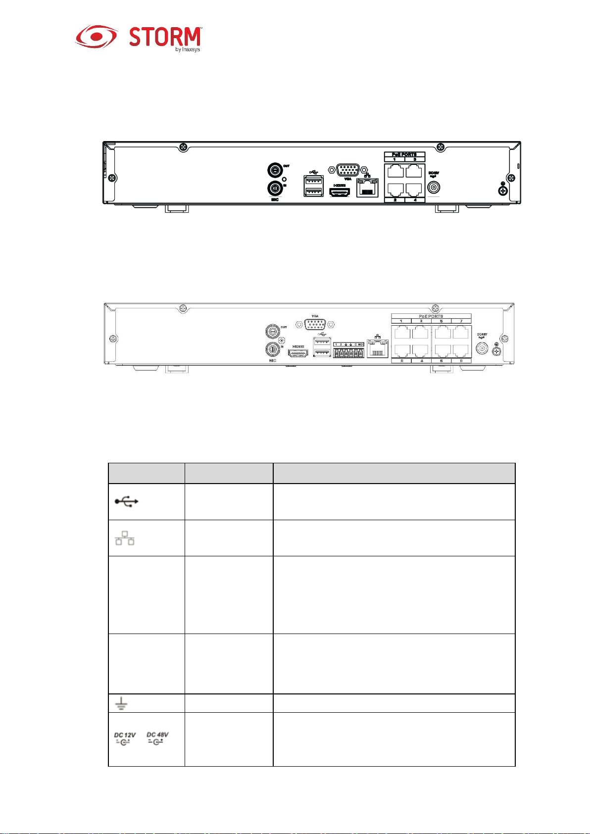
Port Name
Connection
Function
USB2.0 port
USB2.0 port. To connect to the mouse, the USB
storage device, the USB burner, etc.
Network port
10M/100Mbps self-adaptive Ethernet port. It
connects to the network cable.
HDMI
High Definition
Media Interface
High definition audio and video signal output port.
It transmits uncompressed high definition video
and multiple-channel data to the HDMI port of the
display device. The HDMI version is 1.4.
VGA
VGA video
output port
VGA video output port. To output analog video
signal. It can connect to the monitor to view
analog video.
GND
Ground end
/
Power input port
Power socket.
For INS44NVR1T series, input DC 48V/1.5A.
For INS88NVR1T series, input DC 48V/2A.
1.2.2 INS44NVR / INS88NVR Series
The INS44NVR1T rear panel is shown as in Figure 1-1.
Figure 1-1
The INS88NVR1T rear panel is shown as in Figure 1-2.
Figure 1-2
Please refer to the following table for detailed information.
5
Port Name
Connection
Function
MIC IN
Audio input port
Bidirectional audio input port. It is to receive the
analog audio signal output from the devices such
as microphone, pickup.
MIC OUT
Audio output port
Audio output port. It is to output the analog audio
signal to the devices such as the sound box.
Bidirectional audio output.
Audio output on 1-window video monitor.
Audio output on 1-window video playback.
PoE PORT
PoE port
Built-in switch. It supports PoE function.
For PoE series products, you can use this port to
provide power to the network camera.
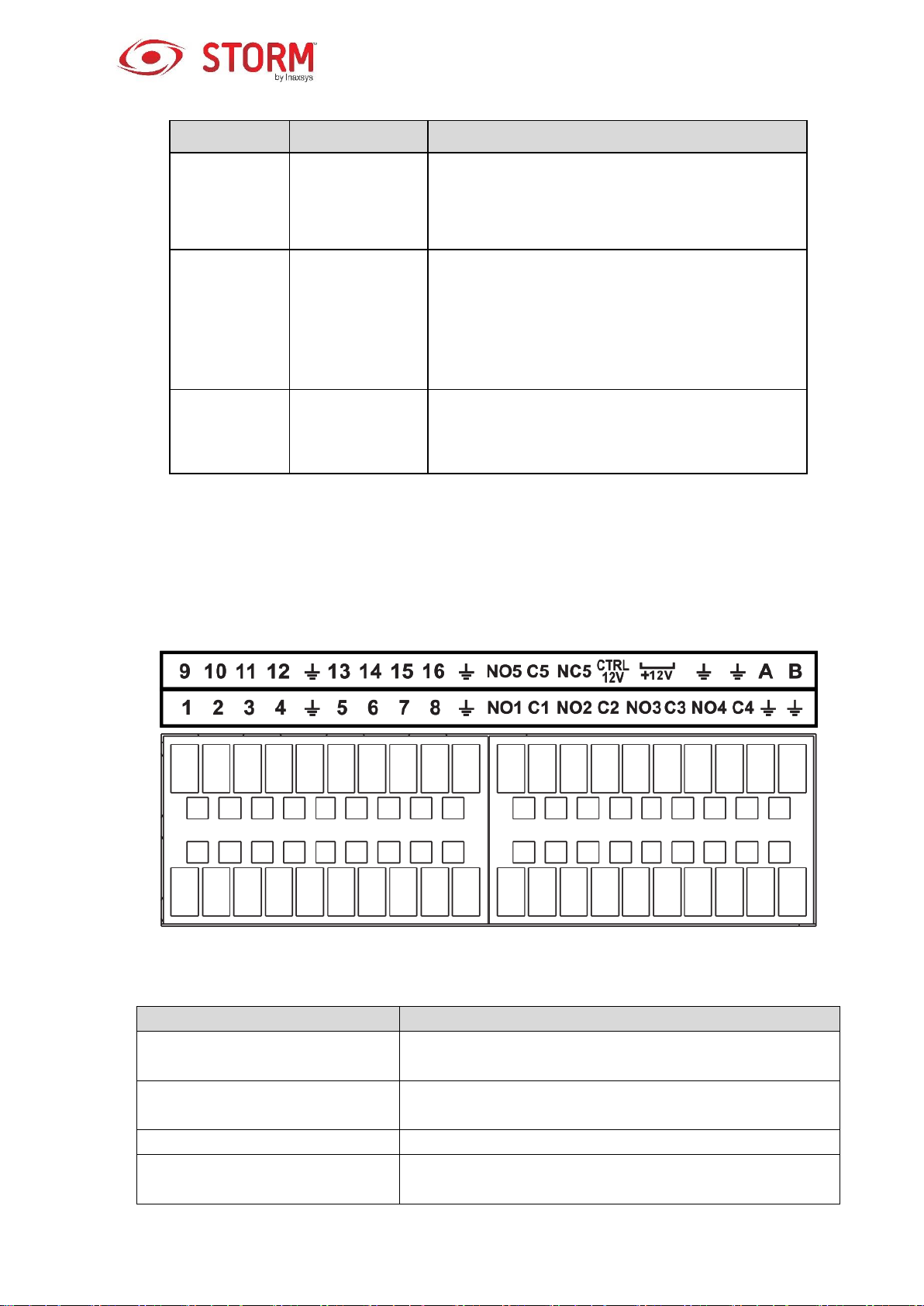
Icon
Function
1-16
ALARM1-ALARM16. The alarm becomes activated in the
low level.
NO1 C1,NO2 C2,NO3 C3,NO4
C4
Four NO activation output groups. (On-off button).
NO5 C5 NC5
One NO/NC activation output group. (On-off button).
CTRL 12V
Control power output. Disable power output when alarm is
canceled. Current is 500mA.
1.3 Alarm Connection
1.3.1 Alarm Port
The alarm port is shown in the figure below (Figure 1-3). The following figure is based on the 78 series.
Figure 1-3
6
+12V
Rated current output. Current is 500mA.
GND
A/B
485 communication port. They are used to control devices
such as PTZ. Please parallel connect 120TΩ between A/B
cables if there are too many PTZ decoders.
Note
Different models support different alarm input ports. Please refer to the specifications sheet for
detailed information.
Slight differences may be found on the alarm port layout.
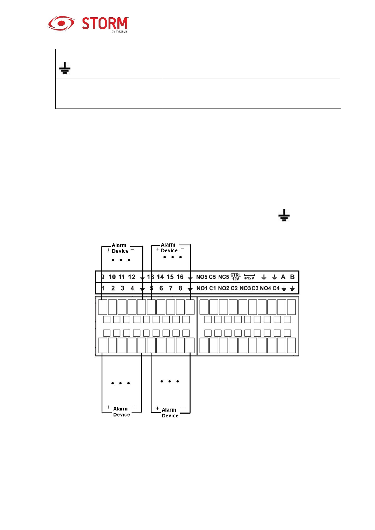
1.3.2 Alarm Input Port
Connect the positive end (+) of the alarm input device to the alarm input port (ALARM IN 1~16) of the
NVR. Connect the negative end (-) of the alarm input device to the ground end ( ) of the NVR.
Note
There are two alarm input types: NO/NC.
When you are connecting the ground port of the alarm device to the NVR, you can use any of the
Figure 1-4
7

Model:
JRC-27F
Material
Silver
Rating
(Resistance
Load)
Rated switch capacity
30V DC 2A, 125V AC 1A
Maximum switch power
125V 160W
Maximum switch voltage
250V AC, 220V DC
Maximum switch current
1A
Insulation
Between points with same
polarity
1000V AC 1minute
Between points with different
polarity
1000V AC 1minute
Between touch and winding
1000V AC 1minute
Voltage surge
Between points with same
polarity
1500V (10×160us)
Length of
“open” time
Maximum 3ms
Length of
“close” time
Maximum 3ms
Longevity
Mechanical
50×106 MIN (3Hz)
Electrical
200×103 MIN (0.5Hz)
Temperature
-40℃ to +70℃
GND ports ( ).
Connect the NC port of the alarm device to the alarm input port (ALARM) of the NVR.
When there is a peripheral source supplying power to the alarm device, please make sure it is
grounded with the NVR.
1.3.3 Alarm Input and Output Port
There is peripheral source supplying power to the external alarm device.
In case of overload, damage to the NVR may occur. Please refer to the following relay specifications
for more information.
A/B cable of the RS485 is for the A/B cable connection of the PTZ speed.
1.3.4 Alarm Relay Specifications
8
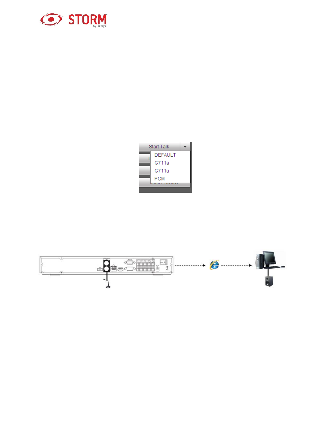
1.4 Bidirectional Audio/Talk
1.4.1 Device-end to PC-end
Device Connection
Please connect the speaker to the first audio input port on the rear panel of the device. Then connect the
earphone or the sound box to the audio output port of the PC.
Login to the Web and then enable the corresponding channel of the real-time surveillance.
Please refer to the following interface to enable bidirectional audio. See Figure 1-5.
Figure 1-5
Listening Operation
At the device end, speak via the speaker or the pickup, and then you can get the audio from the earphone
or sound box at the pc-end. See Figure 1-6.
Figure 1-6
1.4.2 PC-end to the device-end
Device Connection
Connect the speaker or the pickup to the audio output port in the PC and then connect the earphone or
the sound box to the first audio input port in the device rear panel.
Login the Web and then enable the corresponding channel of the real-time surveillance.
Please refer to the above interface (Figure 1-5) to enable bidirectional audio.
9

Left click
mouse
When you have selected a menu item, a left-click of the mouse enables you to
view the menu’s content.
Modify the checkbox or motion detection status.
Click the combo box to pop up the dropdown list
In the Input box, you can select the input methods. Left-click the corresponding
button on the panel and input numeral or English characters (small/capital
letters). This symbol ← stands for the backspace button and this one _
stands for the space button.
In English Input mode: this symbol _ stands for input of a backspace and this
one ← stands for deleting the previous character.
In numerical input mode: this symbol _ stands for clear and this one ← stands
for deleting the previous numeral.
Listening Operation
At the PC-end, speak via the speaker or the pickup, and then you can get the audio from the earphone or
sound box at the device-end. See Figure 1-7.
Figure 1-7
1.5 Mouse Operation
Please refer to the following sheet for mouse operation instruction.
10

Double left
click mouse
Implement special control operation such as double click one item in the file list
to playback the video.
In multiple-windows mode, double left-click one channel to view in full-window.
Double left click current video again to go back to previous multiple-window
mode.
Right click
mouse
In real-time surveillance mode, it pops up the shortcut menu.
To exit the current menu without saving the modification.
Press
middle
button
In numeral input box: increase or decrease numeral value.
To switch the items in the check box.
Page up or page down.
Move mouse
To select current control or move the control.
Drag mouse
To select the motion detection zone.
To select the privacy mask zone.
11

1. Loosen the screws of the upper
cover and side panel.
2. Fix the four screws in the HDD
(turn just three rounds).
3. Place the HDD according
to the four holes on the
bottom.
2 Device Installation
Note
All the installation and operations should conform to your local electric safety rules.
2.1 Check Unpacked NVR
When you receive the NVR, please check whether there is any visible damage. The protective materials
used for the packaging of the NVR can protect against most accidents during transportation. Once the box
is open, check the accessories and the items in accordance with the list. Finally, you can remove the
protective film of the NVR.
2.2 About Front Panel and Rear Panel
The model number on the sticker on the bottom of the NVR is very important; please check that it is the
same as the one on your purchase order.
The label on the rear panel is very important too. Usually we need you to identify the serial number when
we provide you with the after sales service.
2.3 HDD Installation
Important
Please turn off the power before you replace the HDD. The pictures listed below for reference only.
For the first time installation, please make sure whether the HDD has been installed.
You can refer to the Appendix for the HDD space information and the recommended HDD brand. Please
use a HDD of 7200rpm or higher. We don’t usually recommend the PC’s HDD.
Please follow the instructions below to install the hard disk.
2.3.1 INS44NVR / INS88NVR/11HS Series
12
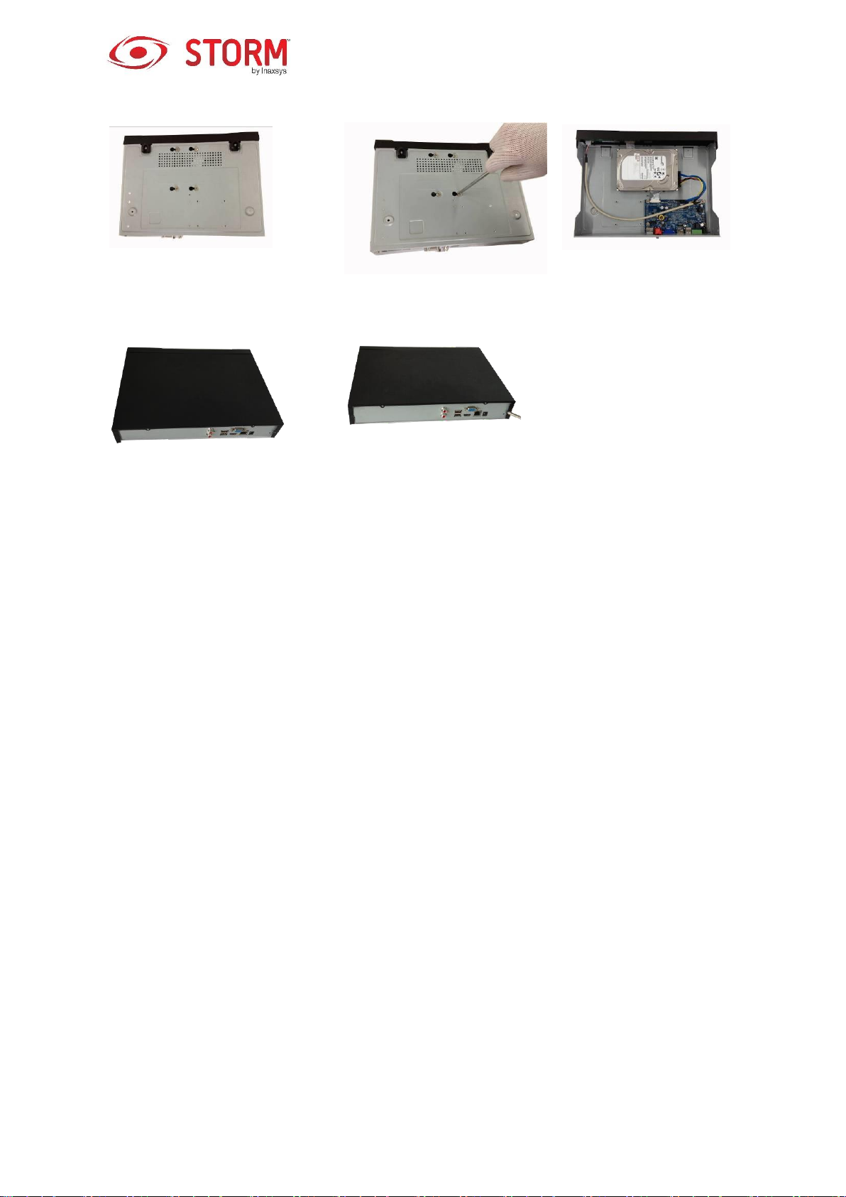
4. Turn the device upside down and
then turn the screws in firmly.
5. Fix the HDD firmly.
6. Connect the HDD cable
and power cable.
7. Put the cover in accordance with
the clip and then place the upper
cover back.
8. Secure the screws in the rear
panel and the side panel.
13
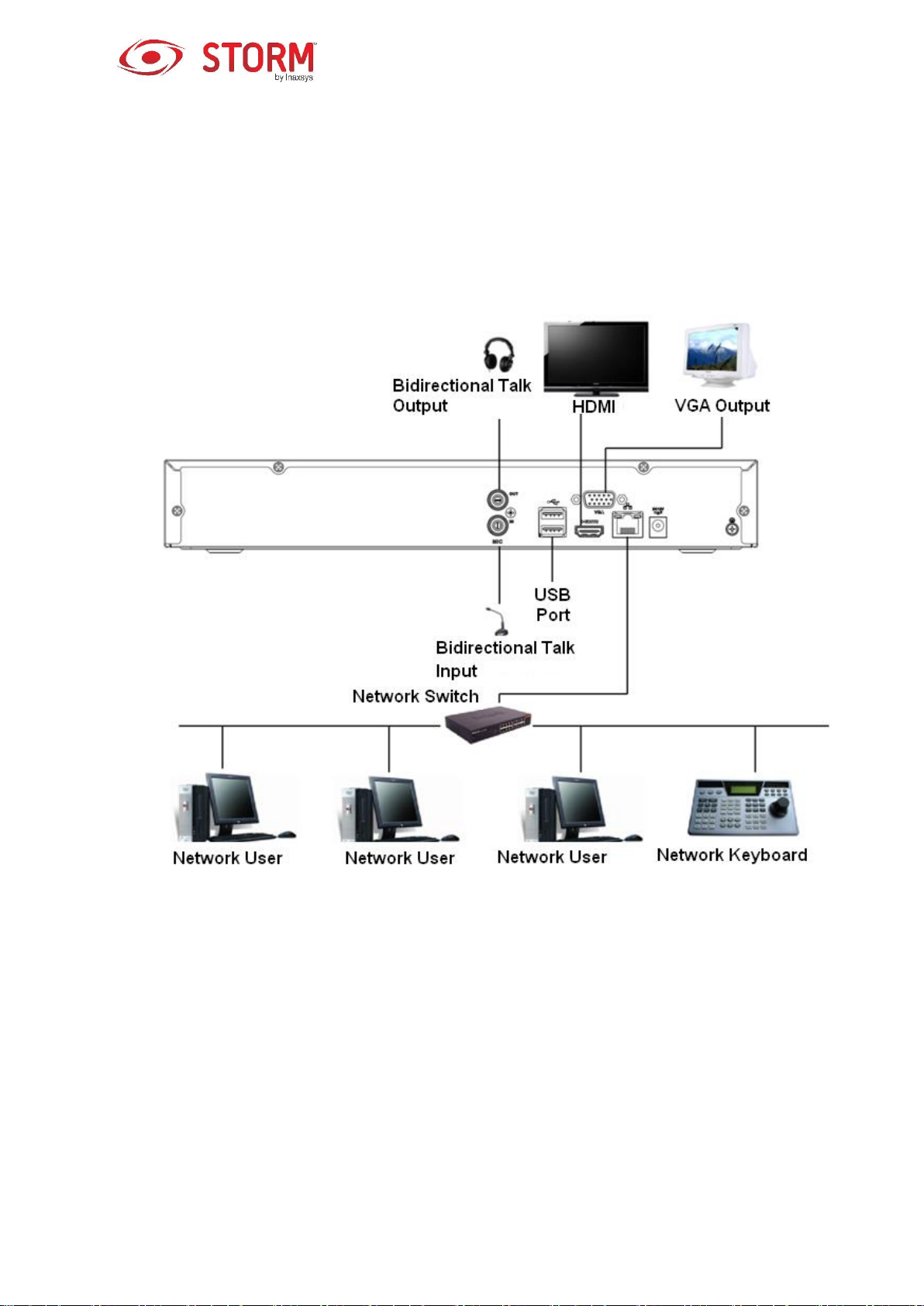
2.4 Connection Sample
2.4.1 INS44NVR / INS88NVR Series
Please refer to Figure 2-1 for connection sample.
Figure 2-1
14

3 Local Basic Operation
3.1 Boot up and Shutdown
3.1.1 Boot up
Caution
Before the boot up, please make sure:
For device security, please connect the NVR to the power adapter first and then connect the
device to the power socket.
The rated input voltage matches the device power on-off button. Please make sure the power
wire connection is OK. Then click the power on-off button.
Always use a stable current, if necessary UPS (uninterruptible power source) is the best
alternative.
Please follow the steps listed below to boot up the device.
Connect the device to the monitor and then connect a mouse.
Connect the power cable.
Click the power button at the front or rear panel and then boot up the device. After the device has
booted up, the system is in multiple-channel display mode by default.
3.1.2 Shutdown
Note
When you see the following dialog box “System is shutting down…” do not click power on-off button
directly.
Do not unplug the power cable or click power on-off button to shutdown the device when the device
is running (especially when it is recording).
There are three ways for you to log out.
1. Main menu (RECOMMENDED):
From Main Menu → Shutdown, select Shutdown from the dropdown list. Click the OK
button and the device will shut down.
2. From the power on-off button on the front panel or on the remote control:
Press the power on-off button on the NVR front panel or on the remote control for more
than 3 seconds to shutdown the device.
15
3. From the power on-off button on the rear panel.
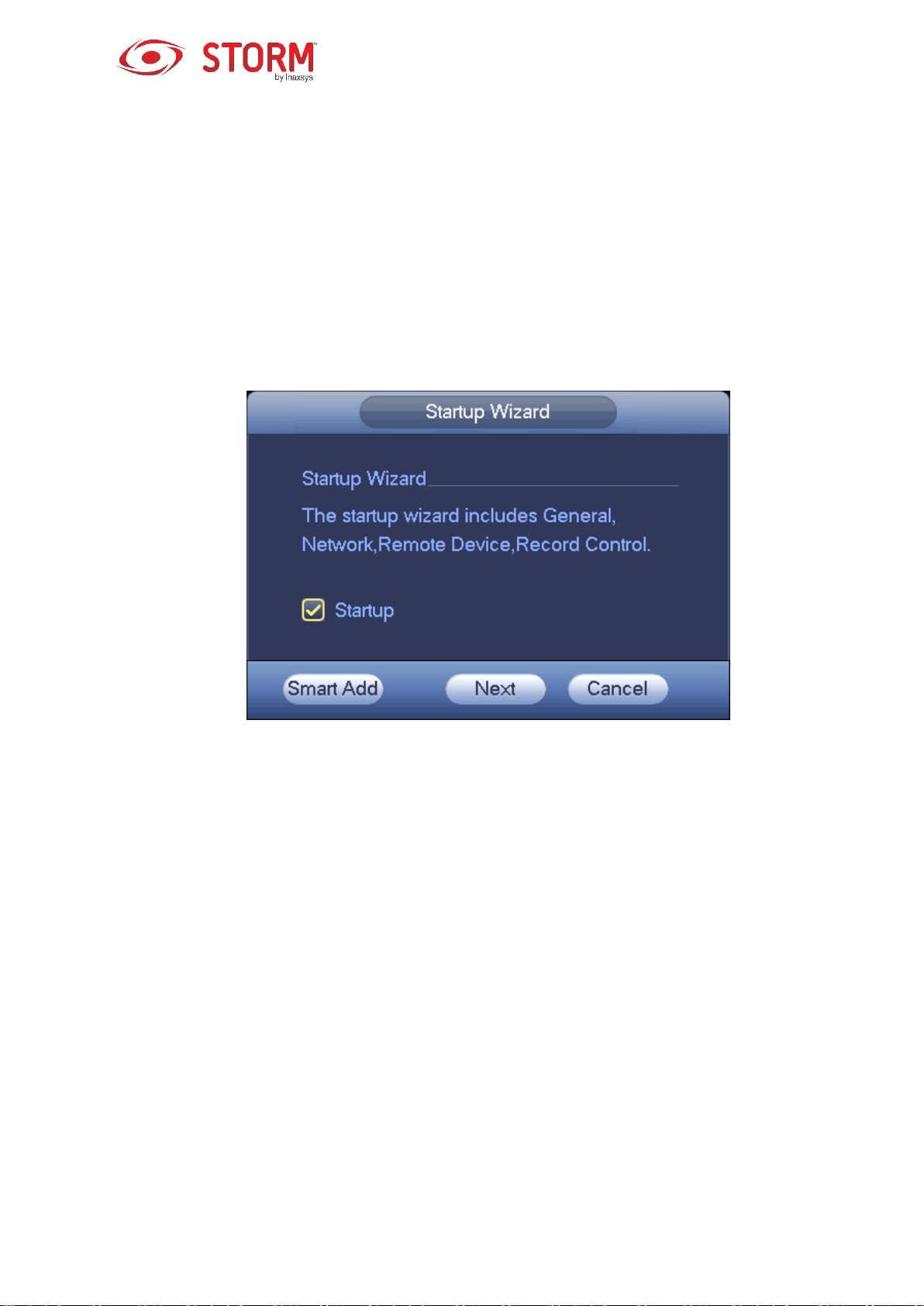
3.2 Startup Wizard
Once the device has successfully booted up, the Startup Wizard is displayed.
Click either the Cancel/Next button, and the system will go to the login interface.
Tips
Check the Startup box here, the system will automatically go to the Startup Wizard next time you boot up.
Uncheck the Startup box, the system will go directly to the login interface next time you boot up.
Figure 3-1
Click Smart Add, Cancel or Next button and the system will go to the login interface. See Figure 3-2.
System has four accounts:
Username: admin. Password: admin. (administrator, local and network)
Username: 888888. Password: 888888. (administrator, local only)
Username: 666666. Password: 666666 (Lower authority user who can only monitor, playback,
backup and etc.)
Username: default. Password: default (hidden user). The hidden user “default” is for the system’s
interior use only and can not be deleted. When there is no login user, the hidden user “default”
automatically logs in. You can set some rights, such as monitoring, for this user so that you can view
a channel without logging in.
16
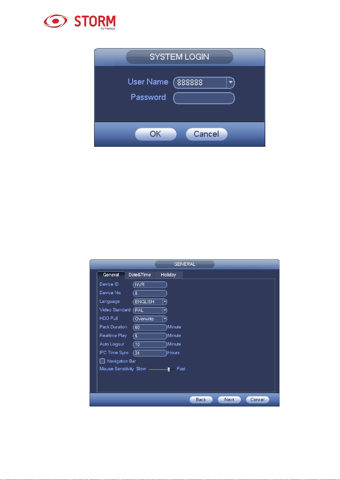
Figure 3-2
Note
For security reasons, please modify the password after your first login.
A three-time login failure within 30 minutes, will result in a system alarm and a five-time login failure will
result in an account lock!
For detailed Smart Add information, please refer to chapter 3.4.
Click the OK button to go to the General interface. See Figure 3-3.
For detailed information, please refer to chapter 3.14.1.
Figure 3-3
17
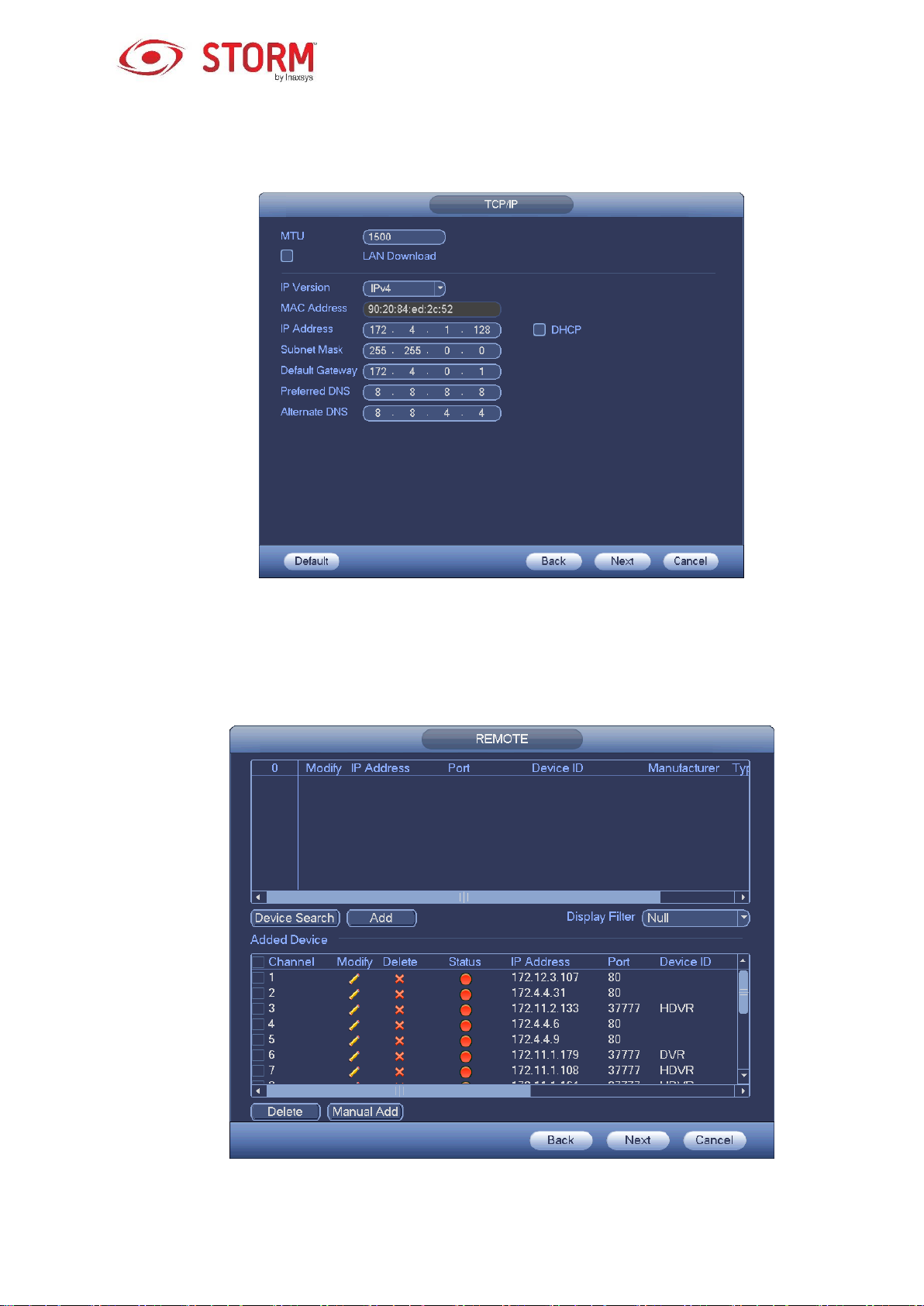
Click the Next button to go to the Network interface. See Figure 3-4.
For detailed information, please refer to chapter 3.12.
Figure 3-4
Click the Next button to go to the Remote Control interface. See Figure 3-5.
For detailed information, please refer to chapter 3.4.
Figure 3-5
18
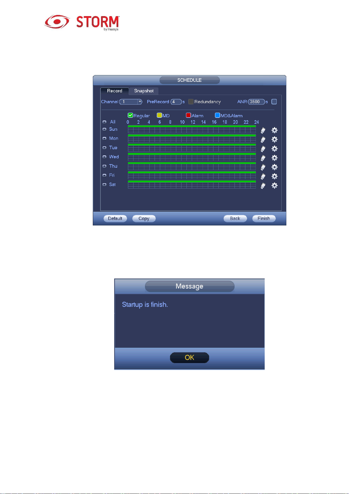
Click the Next button, you can go to Schedule interface. See Figure 3-6.
For detailed information, please refer to chapter 3.8.2.
Figure 3-6
Click the Finish button and the system will display a dialog box. Click the OK button and the Startup Wizard
will be completed. See Figure 3-7.
Figure 3-7
3.3 Navigation Bar
You need to go to the Main menu → Setting → System → General to enable the navigation bar
function. Otherwise you can’t see the following interface.
The navigation bar is shown as below in Figure 3-8.
19
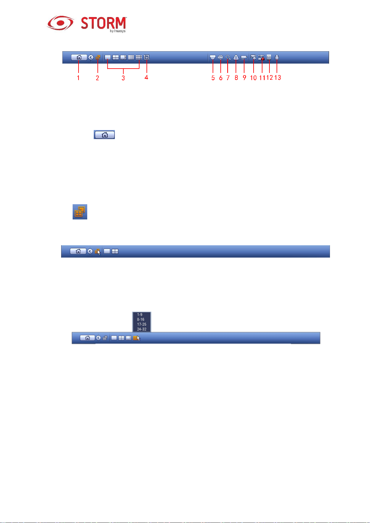
Figure 3-8
3.3.1 Main Menu
Click this button to go to the Main Menu interface.
3.3.2 Dual-Screen Operation
Important
This function is for some series only.
Click on to select screen 2. You will see an interface as shown below in Figure 3-9. It is a
navigation bar for screen 2.
Figure 3-9
Click on any screen split mode; the HDMI2 screen will display the corresponding screens. Now you can
control two screens. See Figure 3-10.
Figure 3-10
Note
Screen 2 function is null if a tour is in process. Please disable the tour function first.
Right now, the screen 2 operation can only be realized on the navigation bar. The operations found
on the menu when you right-click are for screen 1 only.
3.3.3 Output Screen
Select the corresponding window-split mode and output channels.
20

3.3.4 Tour
Click button to enable the tour function. The icon will become like this and you can see that
the tour will be in progress.
3.3.5 PTZ
Click on and the system will go to the PTZ Control interface. Please refer to chapter 3.7.2.
3.3.6 Color
Click the button and the system will go to the Color interface. Please refer to chapter 3.6.4.1.
Make sure that the system is in one-channel mode.
3.3.7 Search
Click this button and the system will go to the Search interface. Please refer to chapter 3.9.2
3.3.8 Alarm Status
Click this button and the system will go to the Alarm Status interface. This will enable you to view
the device’s and channel’s statuses. Please refer to chapter 3.15.1.4.
3.3.9 Channel Info
Click this button and the system will go to the Channel Information Setup interface. It will allow
you to view information regarding the corresponding channel. See Figure 3-11.
Figure 3-11
21

3.3.10 Remote Device
Click this and the system will go to the Remote Device interface. Please refer to chapter 3.4
3.3.11 Network
Click this and the system will go to the Network interface. This allows you to set the network IP
address, the default gateway, etc. Please refer to chapter 3.12.
3.3.12 HDD Manager
Click this and the system will go to the HDD Manager interface. This will allow you to view and
manage the HDD information. Please refer to chapter 3.13.1.
3.3.13 USB Manager
Click this and the system will go to the USB Manager interface. It will allow you to view information
regarding the USB, backups and updates. For detailed information on different topics, please refer to
chapter 3.10.1 for file backup, chapter 3.10.3 for backup log, chapter 3.10.2 for import or export and
chapter 3.15.5 for upgrade.
3.4 Smart Add
When the network camera(s) and the NVR are on the same router or switch, you can use the Smart Add
function to add all the network cameras to the NVR at the same time.
There are two ways for you to go to the Smart Add interface.
From the Startup Wizard, click the Smart Add button. See Figure 3-12.
Figure 3-12
22

On the preview interface, right click the mouse and then select Smart Add off the menu. See Figure
3-13.
Figure 3-13
You will now be redirected to the Smart Add interface. See Figure 3-14.
Figure 3-14
23

Click the Smart Add button and you will see the device enabling the DHCP function. See Figure 3-15.
Figure 3-15
The system will display the following interface for you to confirm the IP address information, if there are
several IP segments. See Figure 3-16.
24

Figure 3-16
You will now see the system automatically adding the IP cameras to the corresponding channels. See
Figure 3-17.
Figure 3-17
25
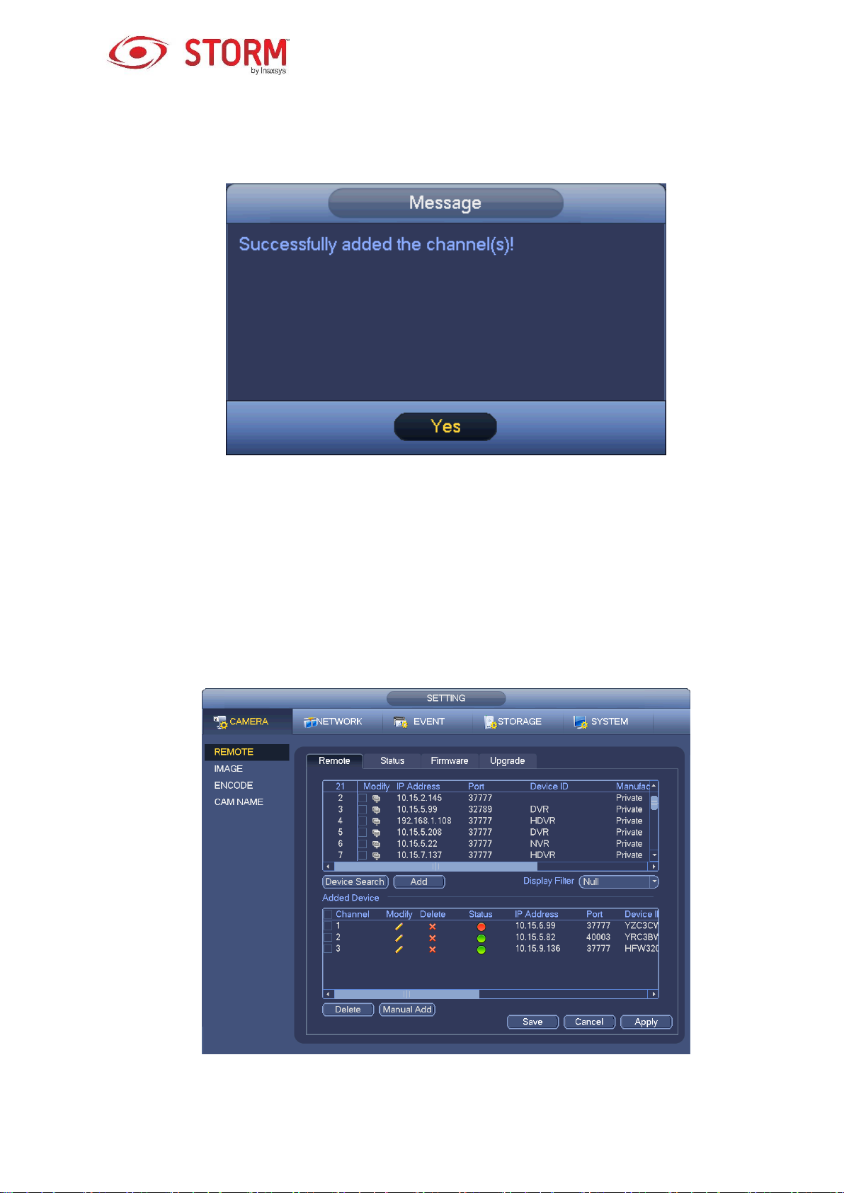
You can see the following dialog box appear after the system has successfully added the network cameras.
See Figure 3-18.
Figure 3-18
3.5 Remote Device
3.5.1 Remote Device Connection
Go to the Main Menu → Setting → Remote or right click the mouse on the Preview interface and then
select the Remote item and you will see the following interface. See Figure 3-19.
Figure 3-19
26

Click the Device Search button and you will be able to view the searched IP addresses in the top pane of
the interface. Double click an IP address or check the box of one IP address, then click the Add button
and you can add the current device to the bottom pane of the interface. The system supports the Batch
Add function.
Click the Manual Add button to add a device directly. Here you can set the TCP/UPD/auto connection
modes. The default setup connection mode is TCP. See Figure 3-20.
Important
Please note that the Manual Add function is for the following brands: Private, Panasonic, Sony, Dynacolor,
Samsung, AXIS, SANYO, Pelco, Arecont, ONVIF, LG, Watchnet, Canon, PSIA, IVC, XUNMEI and
“Custom”. When the type of camera is “Custom”, you can just input the URL address, the user name and
the password to connect to the network camera without considering the network camera manufacturer.
Please contact your network camera manufacturer for the URL address.
Figure 3-20
3.5.2 Shortcut Menu
In the Preview interface for a channel with no IP camera connected, you can click the “+” icon in the centre
of the interface to quickly go to the Remote Device interface. See Figure 3-21.
27

Figure 3-21
3.5.3 Image
Go to the Main Menu → Setting → Camera → Image, you can see the Image interface is shown
below in Figure 3-22.
Channel: Select a channel from the dropdown list.
Saturation: This allows you to adjust the saturation of the monitor’s window. The value ranges
from 0 to 100. The default value is 50. The larger the number, the stronger the color is. This value
has no effect on the general brightness of the whole video. The video color may become too strong
if the value is too high. For the grey part of the video, the distortion may occur if the white balance
is not accurate. Please note the video may not be attractive if the value is too low. The
recommended value ranges from 40 to 60.
Brightness: This allows you to adjust the brightness of the monitor’s window. The value ranges
from 0 to 100. The default value is 50. The larger the number is, the brighter the video is. When you
input the value here, the brighter section and the darker section of the video will be adjusted
accordingly. You can use this function when the whole video is too dark or too bright. Please note
that the video may become hazy if the value is too high. The recommended value ranges from 40 to
60.
Contrast: This allows you to adjust the contrast of the monitor’s window. The value ranges from 0
to 100. The default value is 50. The larger the number is, the higher the contrast is. You can use
this function when the brightness of the whole video is OK but the contrast is not. Please note the
video may become hazy if the value is too low. If this value is too high, the darker section may lack
brightness while the brighter section may be overexposed. The recommended value ranges from 40
to 60.
Auto Iris: This function is for the device’s automatic lens. You can check the box in front of the ON
to enable this function. The automatic iris may change if the light becomes different. When you
disable this function, the iris is at the maximum. The system does not add the automatic iris
function in the exposure control. This function is on by default.
28

Mirror: This function allows you to switch from the top and bottom limit of the video. This function is
disabled by default.
Flip: This function allows you to switch from the left and right limit of the video. This function is
disabled by default.
BLC: This function includes several options: BLC/WDR/HLC/OFF.
o BLC: The device automatically exposes based on the environment’s situation, so that the
darkest area of the video is cleared.
o WDR: For the WDR scene, this function can lower the brightness of the section of highest
brightness and enhance the brightness of the section of lowest brightness. This allows you to
view these two sections clearly at the same time. The value ranges from 1 to 100. When you
switch the camera from no-WDR mode to the WDR mode, the system may lose several seconds
of recorded video.
o HLC: After you have enabled the HLC function, the device can lower the brightness of the
brightest section according to the HLC control level. It can reduce the area of the halo and lower
the brightness of the whole video.
o OFF: This function allows you to disable the BLC function. Please note that this function is
disabled by default.
Profile: This function allows you to set the white balance mode. It has an effect on the general hue
of the video. This function is activated by default. You can select one of these different scene
modes: automatic, sunny, cloudy, home, office, night, disabled, etc. to adjust the video in order to
get the best quality.
o Auto: The automatic white balance is activated. The system can auto-compensate the color
according to the temperature to make sure the video color is proper.
o Sunny: The threshold of the white balance is in the sunny mode.
o Night: The threshold of the white balance is in the night mode.
o Customized: You can set the gain of the red/blue for the channel. The value ranges from 0
to 100.
Day/night: It allows you to set the device’s switching between the color and the B/W modes. The
default setup is automatic.
o Color: The device outputs the video in color.
29

o Auto: The device automatically selects to output the video in color or in B/W according to
the device’s features (general brightness of the video or if there is IR light or not.)
o B/W: The device outputs the video in black and white.
o Sensor: It allows you to set when there is a device that is connected to an IR light.
Please note that some products from the non-IR series support the sensor input function.
Figure 3-22
3.5.4 Channel Name
Go to the Main Menu → Setting → Cam Name, the interface is shown below in Figure 3-23.
Here you can modify the name of the channel. It supports a maximum of 31 characters.
Please note you can only modify the name of the channel of a connected network camera.
30

Figure 3-23
3.5.5 Upgrade
Note
Right now, the NVR can upgrade the IP cameras via the USB device or the WEB. You can upgrade up to
8 network cameras of the same model (or NVR supported) at the same time.
To update the network cameras.
Go to the Main Menu → Setting → Camera → Remote; the interface is as shown in Figure 3-24.
Click the Browse button and then select the upgrade file. Select a channel (or you can select the device
type filter to select several devices at the same time).
Click the Begin button to start the upgrade. You can see the corresponding dialog box once the upgrade
is completed.
31

Figure 3-24
3.5.6 UPNP
Important
Do not connect the switch to the PoE port, otherwise the connection may fail!
Please connect the IP camera to the PoE port on the device’s rear panel (Figure 3-25). The system can
automatically connect to the network camera. Please note the following image is for reference only.
Figure 3-25
3.5.7 Built-in Switch Setup
The built-in switch function is for products with PoE port.
From the Main Menu → Setting → Network → Switch, you can set the switch’s IP address, subnet mask,
gateway, etc. See Figure 3-26.
32
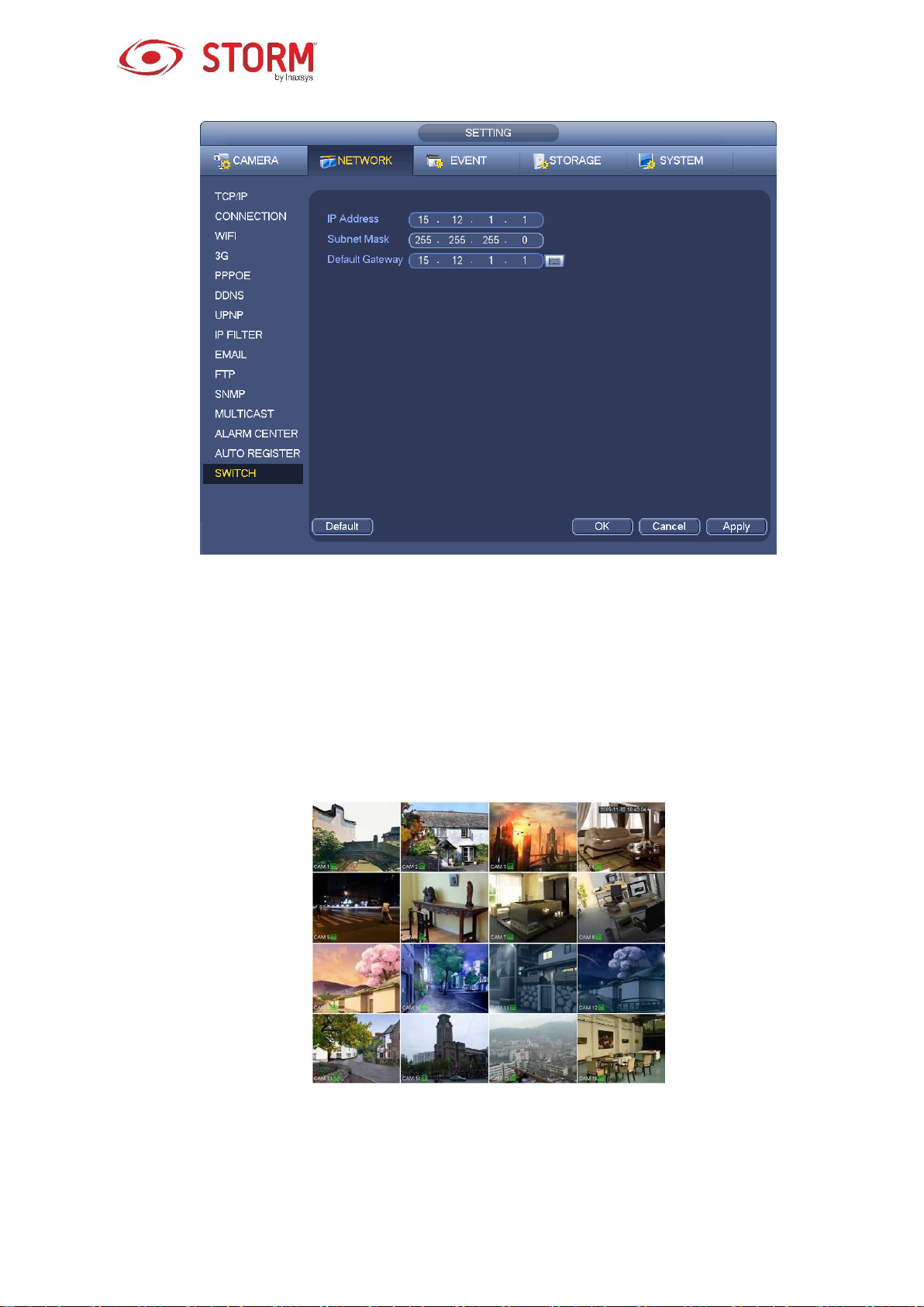
Figure 3-26
3.6 Preview
After the device has booted up, the system will be in multiple-channel display mode. See Figure 3-27.
Please note that the number of displayed windows may vary. The following figure is for reference only.
Please refer to chapter Error! Reference source not found. Specifications for the number of windows
that your product supports.
Figure 3-27
3.6.1 Preview
If you want to change the system’s date and time, you can refer to the General settings (Main Menu
33
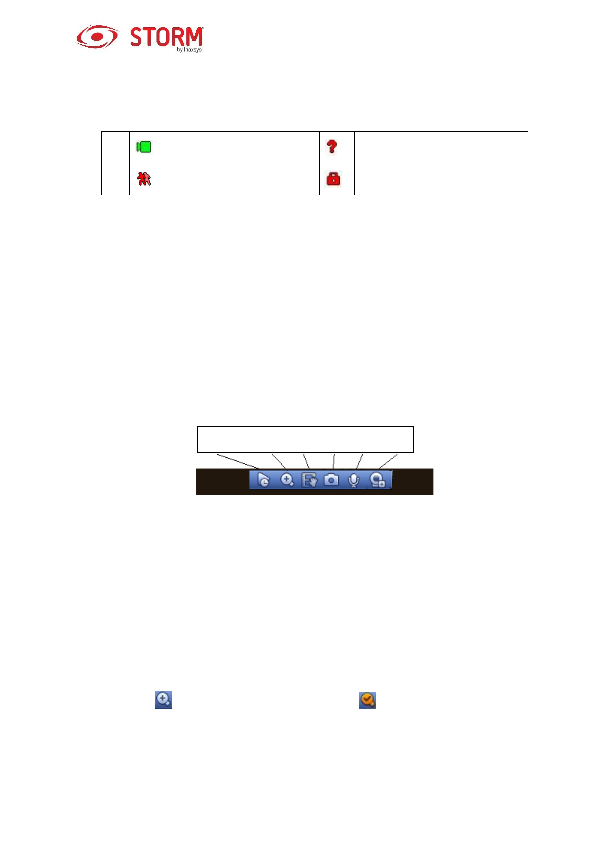
1
Recording status
3
Video loss
2
Motion detection
4
Camera lock
1 2 3 4 6 7
→ Setting → System → General). If you want to modify the channel name, please refer to the
Display settings (Main Menu → Camera → CAM name). Please refer to the following table for
detailed information.
Tips
Preview-drag: If you want to change the position of channel 1 and channel 2 when you are
previewing, you can left click the mouse in the channel 1, drag it to channel 2, release the
mouse and you will have switched the channel 1 and channel 2 positions.
Use the mouse’s middle button to control the window splitting: You can use the mouse’s
middle button to switch the number of window splits.
3.6.2 Preview Control Interface
Move your mouse to the top centre of the video of your current channel, the system will display the
preview control interface. See Figure 3-28. If your mouse stays in this area for more than 6 seconds
without doing anything, the control bar will automatically disappear.
Figure 3-28 Digital Channel
1. Real-time Playback
This allows you to playback the last 5 to 60 minutes of recording of the current channel.
Please go to the Main Menu → Setting → System → General to set the real-time playback time.
The system may display a dialog box if there is no such record in the current channel.
2. Digital Zoom
This allows you to zoom in a specific zone of the current channel. It supports zoom in function of
multiple-channel.
Click this button , and it will then convert to this button .
There are two ways for you to zoom in.
Drag the mouse to a specific zone, you will see an interface as shown in Figure 3-29.
34

Figure 3-29
Place the cursor at the centre of the zone you want to zoom in, then move the middle button of
the mouse and you will see an interface as shown in Figure 3-30.
Figure 3-30
Right click the mouse to cancel the zoom and go back to the original interface.
3. Manual Recording Function
This allows you to backup the video of the current channel to the USB device. The system can’t
backup the video of multiple channels simultaneously.
Click this button and the system will begin recording. Click it again and the system will stop recording.
You can find the recorded file on the flash drive.
4. Manual Snapshot
Click this button to perform a snapshot 1 to 5 times. The snapshot file is saved on the USB device
or HDD. You can go to the Search interface (chapter 3.9) to view it.
5. Bidirectional Audio
If the connected front-end device supports bidirectional audio function, you can click this button
to start the bidirectional audio function; the icon will now appear like this . The rest of the
bidirectional audio buttons of the digital channels change as well.
Click this button again and you can cancel the bidirectional audio and the bidirectional audio
35

buttons of other digital channels will also become .
6. Remote Device
Go to the shortcut menu. Click it to go to the remote device interface to add/delete remote devices or
to view its corresponding information. Please refer to chapter 3.5.2 for detailed information.
3.6.3 Right Click Menu
After you logged into the device, do a right click with your mouse to display the shortcut menu. Please see
Figure 3-31.
Window Split Mode: You can select the number of windows and then select the channels.
PTZ: Click it to go to PTZ interface.
Auto Focus: It is to set the auto focus function. Please make sure the connected network camera
supports this function.
Color Setting: Set the videos corresponding information.
Search: Click it to go to the Search interface to search and playback a recorded file.
Recording Control: Enable/disable recording on the channel.
Alarm Output Mode: It is to set the alarm output mode.
Remote Device: To search and add a remote device.
Alarm Output: Generates an alarm output signal manually.
Main Menu: To go to the system’s main menu interface.
Tips:
Do a right click with the mouse to go back to the previous interface.
Figure 3-31
36

Item
Note
Period
There are two periods in one day. You can set different
sharpness, brightness and contrast for different periods.
Effective Time
Check the box here to enable this function and then set the
time period.
Sharpness
The value here is to adjust the edge of the video. The value
ranges from 0 to 100. The larger the value is, the clearer the
edge is, and vice versa. Please note that there will be noise if
the value here is too high. The default value is 50 and the
recommended value ranges from 40 to 60.
Brightness
It is to adjust the monitor’s window brightness. The value
ranges from 0 to 100. The default value is 50.
The larger the number, the brighter the video. When you input
3.6.4 Preview Display Effects Setup
3.6.4.1 Video Color
Here you can set the hue, brightness, contrast, saturation, gain, white level, color mode, etc. See
the Figure 3-32.
Figure 3-32
Please refer to the following sheet for detailed information.
37

Item
Note
the value here, the bright section and the dark section of the
video will be adjusted accordingly. You can use this function
when the whole video is too dark or too bright. Please note the
video may become hazy if the value is too high. The
recommended value ranges from 40 to 60.
Contrast
It is to adjust the monitor’s window contrast. The value ranges
from 0 to 100. The default value is 50.
The larger the number, the higher the contrast is. You can use
this function when the whole video brightness is OK but the
contrast is not. Please note that the video may become hazy if
the value is too low. If this value is too high, the darker section
may lack brightness, while the brighter section may be over
exposed. The recommended value ranges from 40 to 60.
Saturation
It is to adjust the monitor’s window saturation. The value
ranges from 0 to 100. The default value is 50.
The larger the number, the stronger the color is. This value has
no effect on the general brightness of the whole video. The
video color may become too strong if the value is too high. For
the grey part of the video, the distortion may occur if the white
balance is not accurate. Please note that the video may not be
attractive if the value is too low. The recommended value
ranges from 40 to 60.
Gain
The gain adjustment is to define the gain value. The default
value may vary due to different device models. The smaller the
value, the lower the noise; but the brightness is also too low in
the dark environments. If the value is higher, the video
brightness can be enhanced, but the video noise may become
too clear.
Color mode
The color mode includes several modes such as: standard,
color, bright, gentle. When you select a color mode, the
sharpness, brightness, contrast, etc. will automatically switch
to that of the corresponding color mode’s setup.
38

3.6.4.2 Display
From the Main Menu → Setting → System → Display, you can go to the following interface. See Figure
3-33.
Here you can set the menu and the video preview effect. All your operations here won’t affect the recorded
file and playback effects.
Figure 3-33
Now you can define the following parameters.
Resolution: There are five options: 1280×1024 (Default), 1280×720, 1920×1080, 1024×768 and
3840×2160. Please note that the system needs to reboot to activate the current setup. The
3840×2160 resolution is only for some series.
VGA+HDMI2: Is for dual-screen operation. Please select from the dropdown list according to your
actual situation, then press the Apply button. The system will need to reboot to activate the new
setup. For example, selecting 32+4 means that for VGA the system supports maximum a 32 window
split and for HDMI2 the system supports maximum a 4 window split.
Transparency: Here you can adjust the transparency, the value will range between 128 and 255.
Channel Name: Here you can modify the channel’s name. The system will support up to 25 digits
(the number of digits may vary in different series). Please note that all your modifications here will
only apply to the NVR local end. You need to open the Web or Client end to refresh the channel’s
name.
39

Time Display: You can choose to display or not the time when the system is in Playback mode.
Channel Display: You can select to display or not the channel name when the system is in
Playback mode.
Image Enhance: Check the box here to optimize the margin of the preview video.
Original Scale: Check the box here to restore the video’s original scale.
Click the OK button to save the current setup.
3.6.4.3 TV Adjust
Note
Some series products support the TV Adjust function.
From the Main Menu → Setting → System → Display → TV Adjust to pass to the following interface.
See Figure 3-33. Here you can set the Margins and the Brightness.
Figure 3-34
3.6.5 Preview Tour Parameters
This is where you can define the Preview Display Mode, the Channel Display Sequence and the Tour
Setup.
40

Preview Display Mode: Right click your mouse on the Preview interface to view the menu and select
the number of preview windows and the channel.
Channel Display Sequence: In the preview interface, if you want to change the channel 1 and
channel 16 positions, simply right click on the channel 1 video window, drag it to the channel 16 video
window, and release the button.
Tour Setup: This is where you can set the preview window channel display mode and interval.
Follow the steps listed below.
From the Main Menu → Setting → System → Display → Tour, you will see an interface like the one in
Figure 3-35.
Here you can define the tour parameters.
Enable Tour: Check this box to enable the touring function. The general tour supports all types of
window split modes.
Interval: Input the proper interval value here. The value ranges from 1-120 seconds.
Motion Tour Type: The system supports 1/8-window touring. Please note you will need to go to
the Main Menu → Setting → Event → Video Detect → Motion Detect to enable the tour function.
Alarm Tour Type: The system supports 1/8-window touring. Please note you need to go to the
Main Menu → Setting → Event → Alarm to enable the tour function.
Window Split: This is where you set the window split mode.
Figure 3-35
41

Tips
On the navigation bar, click / to enable/disable the Tour.
Click the Save button to save the current setup.
3.7 PTZ
Note
Before you control the PTZ, please make sure that the PTZ decoder and the NVR network connections
are OK and that the following settings are correct.
3.7.1 PTZ Settings
Cable Connection
Please follow the steps below for the cable connection:
Connect the dome RS485 port to the NVR RS485 port.
Connect the dome video output cable to the NVR video input port.
Connect the power adapter to the dome.
In the Main Menu, go to Setting → System → PTZ to see an interface like the one shown in Figure
3-36.
Here you can define the following items:
Channel: Select the current camera channel.
PTZ Type: There are two types: local/remote. Select the local mode if you are connecting the
RS485 cable to the Speed dome (PTZ). Select the remote mode if you are connecting to the
network PTZ camera.
Protocol: Select the corresponding PTZ protocol, such as PELCOD.
Address: The default address is 1.
Baud Rate: Select the corresponding baud rate; the default value is 9600.
Data Bit: Select the corresponding data bits; the default value is 8.
Stop Bit: Select the corresponding stop bits; the default value is 1.
42

Parity: There are three options: odd/even/none; the default setup is none.
Figure 3-36
If you are connecting to the network PTZ, the PTZ type will be Remote. See Figure 3-37.
Figure 3-37
43

3.7.2 PTZ Control
After completing all the settings, please click the Save button. Click the “Fn” Button on the front panel
or the “Fn” key on the remote control, and an interface like the one in Figure 3-38 will be displayed.
You can only go to the PTZ control interface when you are in a 1-window display mode.
Figure 3-38
The PTZ setup is like displayed in See Figure 3-39.
If the device does not support a function, the command name will be in grey. PTZ function is only valid
in the 1-window display mode.
Here you can control the PTZ direction, speed, zoom, focus, iris, preset, tour, scan, pattern, light, rotation,
etc. The Speed function allows you to control the PTZ movement speed. This value ranges from 1 to 8.
Speed 8 being faster than speed 1. You can use the remote control to configure the different functions.
By using the and buttons you will be able to zoom in or out, create definition for the focus and
add or remove brightness for the iris.
The PTZ rotation supports 8 directions. Although, if you use the direction buttons on the front panel, there
are only four directions: up/down/left/right.
44

Name
Key
Function
Shortcut
Key
Key
Function
Shortcut
Key
Zoom
Near
Far
Focus
Near
│
Far
►│
Iris
Closed
Open
Figure 3-39
In the center of the eight direction arrows, there is a 3D intelligent positioning key, SIT, like the one shown
in Figure 3-40. Make sure your protocol supports this function, if so you can use the mouse to control it.
When you click on this key, the system will go back to the single screen mode. Drag the mouse in the
screen to adjust the size of the section. The dragged zone supports speeds of 4X to 16X. It can also
perform PTZ automatically. The smaller the zone that was dragged, the higher the speed.
Figure 3-40
In the interface like in Figure 3-39, click on the to open the menu, you can then set the Preset,
Tour, Pattern, Scan, etc. See Figure 3-41.
Figure 3-41
45

Icon
Function
Icon
Function
Preset
Flip
Tour
Reset
Pattern
AUX
Scan
AUX On/Off
Rotate
Go to menu
Refer to the following table for detailed information.
Also, depending on the different protocols, the above interface may vary slightly. When the key or
button is grey, it can’t be selected and the function is null.
Do a right click with the mouse or click the ESC button on the front panel to go back to the interface
like in Figure 3-39.
3.7.2.1 PTZ Function Setup
Click on this icon to go to the following interface and set the Preset, Tour, Pattern and Scan
functions. See Figure 3-42.
Figure 3-42
Preset Setup
In Figure 3-42, click the Preset button and use the eight direction arrows to adjust the camera to the
desired position. The interface is like the one shown in Figure 3-43.
46

Click the Set button and then input the Preset number. Click Set button again to save the current preset.
Figure 3-43
Tour Setup
In Figure 3-42, click the Tour button.
Input the Preset number and the Patrol (Tour) number. Click on the Add Preset button to add the current
Preset to the Tour. See Figure 3-44.
Tips
Repeat the above steps to add more Presets to the Tour. Click on the Del Preset button to remove it from
the Tour. Please note some protocols do not support the Delete Preset function.
Figure 3-44
Pattern Setup
In Figure 4 42, click the Pattern button and input a pattern number.
Click the Begin button to start the chosen Pattern operation or you can go back to the interface like in
Figure 4 39 to use the zoom/focus/iris/direction functions.
In Figure 4 42, click the End button.
47

Figure 3-45
Scan Setup
In Figure 3-42, click on the Scan button.
Use the direction arrow buttons to set the camera’s left limit and then click on the Left button.
Use the direction arrow buttons to set the camera’s right limit and then click on the Right button. Now the
Scan setup is complete.
Figure 3-46
3.7.2.2 Call PTZ Function
Call Preset
In Figure 3-41, input the Preset value and then click on this icon to Call a Preset. Click on this
icon again to Stop a Call.
Call Pattern
In Figure 3-41, input the Pattern value and then click on this icon to Call a Pattern. Click on
48

this icon again to Stop a Call.
Call Tour
In Figure 3-41, input the Tour value and then click on this icon to Call a Tour. Click on this
icon again to Stop a Call.
Call Scan
In Figure 3-41, input Scan value and then click to Call a Scan. Click on this icon again
to Stop a Call.
Rotate
In Figure 3-41 , click on this icon to enable the camera to rotate.
Note
The Preset, Tour and Pattern all need a value to be the Control Parameters. You can configure it
as necessary.
You need to refer to your camera’s user manual for the AUX definition. In some cases, it can be
used for special purposes.
AUX
Click on this icon and the system will open the following interface. The options here will vary
according to the protocol. The AUX Number corresponds to the On/Off button of the AUX function on the
decoder. See Figure 3-47.
Figure 3-47
49

3.8 Record and Snapshot
The Record/Snapshot function priority is: Alarm → Motion Detect → Schedule.
3.8.1 Encode
3.8.1.1 Encode
The Encode configuration allows you to define the IP camera’s encoding mode, its resolution, the bit
stream type, etc.
From the Main Menu → Setting → System → Encode, an interface like the one shown in Figure 3-48
will appear.
Channel: Select the channel you want.
Type: Select from the dropdown list one of these three options: regular/motion detect/alarm. You
can define the encoding parameters for different recording types.
Compression: The system supports H.264, MPEG4, MJPEG, etc.
Resolution: The mainstream resolution type depends on the IP camera’s encoding configuration.
Generally, the resolutions are D1/720P/1080P.
Frame Rate: It ranges from 1fps to 25fps in NTSC mode and 1fps to 30fps in PAL mode.
Bit Rate Type: The system supports two types: CBR and VBR. In VBR mode, you can define the
video quality.
Quality: There are six levels ranging from 1 to 6. The sixth level has the highest image quality.
Video/Audio: You can enable or disable the video/audio. Once you enable the audio function for
one channel, the system may enable the audio function for the rest of the channels by default.
Copy:After you complete the setup, you can click the Copy button to copy the current setup to the
other channels. You will see an interface like the one in Figure 3-51. The current channel number is
in grey. Check the numbers to select the desired channel(s) or you can check the ALL box to select
all the channels. Click on the OK button in Figure 3-51 and Figure 3-49 respectively to complete the
setup. Once you have checked the All box, you have set the same encoding setup on all the
channels. The Audio/Video Enable box, the Overlay button and the Copy button are shielded.
Please highlight or check these boxes to select the corresponding functions.
50

Figure 3-48
3.8.1.2 Overlay
Click on the Overlay tab and you will see an interface as shown in Figure 3-49.
Cover Area: This is where you determine an area section to cover. You can drag your mouse to
define the proper section size. The system supports a maximum of 4 zones in a one channel video.
You can configure it with the Fn button or the direction arrow buttons.
Preview/Monitor: There are two types of cover areas: Preview and Monitor. Preview means the
privacy mask zone can’t be viewed by the user when the system is in Preview mode. Monitor
means the privacy mask zone can’t be viewed by the user when the system is in Monitor mode.
Time Display: You can select whether or not the system displays the time during playback. Click
on the Setup button and then drag the title to the desired position on the screen.
Channel Display: You can select whether or not the system displays the channel’s number during
playback. Click on the Setup button and then drag the title to the desired position on the screen.
51
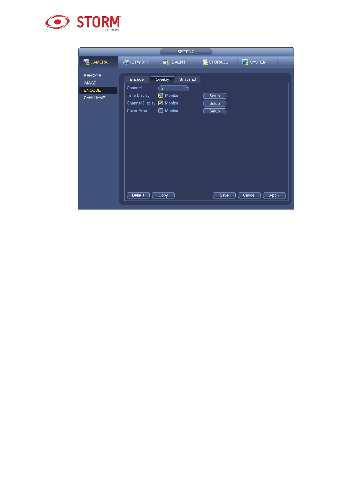
Figure 3-49
3.8.1.3 Snapshot
Here you can define the snapshot mode, the picture size, its quality and frequency. See Figure 3-50.
Snapshot Mode: There are two modes: regular and trigger. If you set the mode to regular, you
need to determine a snapshot frequency. If you set the mode to trigger, you need to determine what
will activate the snapshot function.
Image Size: This is where you can define the snapshot picture size.
Image Quality: Here you can set the quality of the snapshot, this value ranges from 1 to 6.
Snapshot Frequency: This is where you to set a schedule for the snapshots.
52

3.8.2 Schedule
Figure 3-50
Figure 3-51
The recording type priority is: Alarm → Motion Detect → Regular.
3.8.2.1 Recording Schedule
This is where you set the recording time, the recording plan, etc. Note that the system is by default in
53

24-hour recording mode after its first boot up.
From the Main Menu → Setting → Storage → Schedule you can go to Schedule menu like in Figure
3-55. There is a total of six periods.
Channel: Please select the channel number first. You can select “All” if you want to configure all
the channels.
o : Synchronizing button. Check these boxes for your desired dates; all the checked
days can be edited together. Now the synchronizing button will look like this .
o : Click this button to delete a recording type for a period.
Record Type: Please check this box to select the corresponding recording type. There are four
types: Regular/MD (motion detection)/Alarm/MD&Alarm.
Week Day: There are eight options: each day from Sunday to Saturday and All.
Holiday: It is to configure a holiday. Please note you need to go to the General interface (Main
Menu → Setting → System → General) to first add a holiday, otherwise you will not see this
option.
Pre-record: The system can start to pre-record the video before the event appears in a file. You
can select a value ranging from 1 to 30 seconds depending on the bit stream.
Redundancy: The system supports a redundancy backup function. This allows you to backup
recorded files on two disks. You can check the Redundancy button to activate this function. Please
note, before enabling this function, you must set at least one HDD as redundant. Go to Main menu
→ Setting → Storage → HDD Manager. Please note this function does not apply if there is only
one HDD.
ANR: This allows you to save a video to the SD card of the network camera in case the network
connection fails. The value ranges from 0 to 43200 seconds. After the network connection is
resumed, the system can get the video from the SD card and there is no risk of losing any
recordings.
Period Setup: Click this button located next to a date or a holiday, an interface like the one
shown in Figure 3-56 will appear.
Please follow the steps listed below to manually configure the period.
a) Select a channel you want to configure. See Figure 3-52.
54

Figure 3-52
b) Choose the recording type. See Figure 3-53.
Figure 3-53
c) Manually draw the recording periods. There are six periods in one day, see Figure 3-54.
Figure 3-54
Check the box to select the desired days. After completing all the setups, click the Save button and
the system will go back to the previous menu.
This is what the color bars represent:
The Green color stands for regular recording, Yellow stands for motion detection (MD) recording and
Red represents alarm recording, White means both MD and alarm recording is selected. When MD
and alarm recording has been selected this means the system will not record during only motion
detection, nor when only an alarm occurs.
55

Figure 3-55
Figure 3-56
Quick Setup
The Copy function allows you to copy one channel’s setup to another. After having completed the
configuration of channel 1, click on the Copy button. See the interface in Figure 3-57. The current channel
number will be in grey, like the channel 1. You can now select the channels on which you want to paste
the channel 1 configuration onto, like channel 5/6/7, etc. If you want to copy the channel’s current
configuration to All the other channels, you can simply check the “All” box instead. Click on the OK button
to save the current copying setup. Then, click on the OK button in the Encode interface and the Copy
function will have been completed successfully.
Please note that if you select the All button in the interface like in Figure 3-57, the recording setup for all
56

the channels will be the same and the Copy button will appear hidden.
Figure 3-57
3.8.2.2 Snapshot Schedule
Go to the Main Menu → Setting → Storage → Record or do a right-click with your mouse on the Preview
interface, then select the recording item. See Figure 3-58.
Select the desired channel and then check the Enable under the Snapshot function. Click the Save button.
Figure 3-58
57
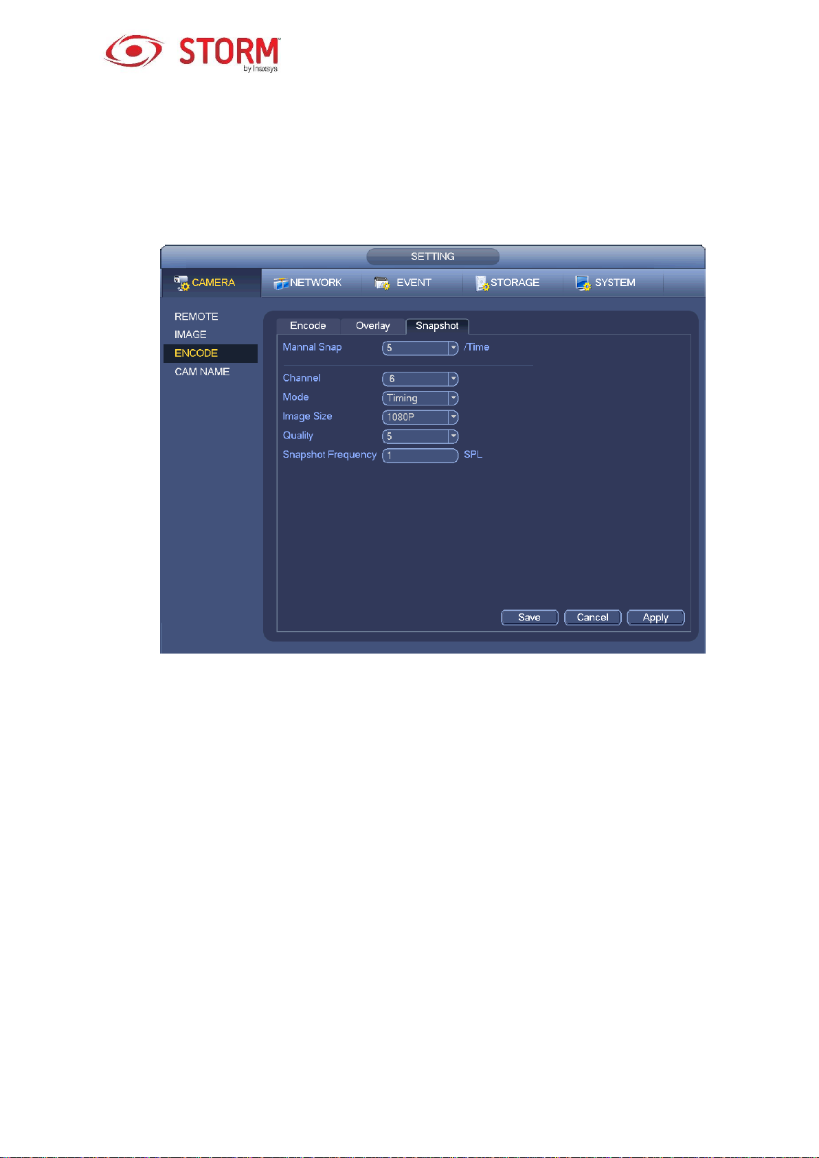
From the Main Menu → Setting → Camera → Encode → Snapshot, you will be redirected to the
Snapshot interface. See Figure 3-59.
Select a Channel number from the dropdown list, then select Timing (Schedule) from the Mode dropdown
list and set the Image Size, the Quality and the Snapshot Frequency.
Figure 3-59
To go to the Snapshot Schedule menu, start from the Main Menu → Setting → Storage → Schedule,
the Schedule interface will be like the one in Figure 3-55. Here you can configure the Snapshot periods.
There are a total of six periods in one day. Please refer to Chapter 3.8.2.1 for the detailed configuration
instructions as the setup steps are generally the same.
58

Figure 3-60
Note
Please note that the Trigger snapshot has a higher priority than the Regular snapshot. If you have
enabled these two types at the same time, the system will activate the trigger snapshot when an alarm
occurs, and use the regular snapshot at other times.
Only the Trigger snapshot can send out a picture via email. But, you can upload the picture to a FTP
server.
3.8.3 Motion Detect Recording/Snapshot
3.8.3.1 Motion Detect Recording
a) From the Main Menu → Setting → Event → Detect, you will be redirected to an interface like in
Figure 3-61.
59

Figure 3-61
b) Select Motion Detect from the Event Type dropdown list. Select a channel number from the
dropdown Channel list and then check the Enable button to enable the motion detection function.
c) Click on the Region button to setup a motion detection zone. There are 396(PAL)/330(NTSC)
small zones. The Green zone is your cursor’s current position. The Grey zone is the motion
detection zone. The Black zone is the disarmed zone. You can click on the Fn button to switch
between the Arm mode and Disarm mode. In the Arm mode, you can click the direction buttons
to move the green rectangle to define the motion detection zone. After you have completed this
setup, please click on the ENTER button to exit the current setup. Remember to click on the Save
button to save the current configuration. If you click on the ESC button to exit the Region Setup
interface, the system will not save your setup.
d) Period: Click on the Setup button and you will see an interface like the one shown in Figure 3-84.
Here you can configure the motion detection period. The system only enables motion detection
in the specified periods. It is not for video loss or tampering. There are two ways for you to
configure the periods and the system only supports 6 periods in one day.
o In Figure 3-84, check off this button for the desired days and all the checked days can
be edited together. This button will now appear like this . Click on this button
to delete a recording type from a period.
60

o In Figure 3-84, click on this button located at the end of the day or holiday row and you
will see an interface like the one shown in Figure 3-85. There are four recording types: regular,
motion detection (MD), alarm, MD & alarm.
e) Set the Sensitivity. Level six is the one with the highest sensitivity.
f) Click on the Save button to complete the Motion Detect setup.
g) From the Main Menu → Setting → Storage → Schedule you will get an interface like the one
in Figure 3-55.
h) Configure the motion detection recording channel and the time period. The recording type will be
Motion Detection (MD). Please refer to chapter 3.8.2.
i) Click the Copy button to copy the current setup to other channel(s).
j) Click the OK button to complete the motion detection recording setup.
Figure 3-62
61

Figure 3-63
3.8.3.2 Motion Detection Snapshot
a) From the Main Menu → Setting → Camera → Encode → Snapshot, you will see the Snapshot
interface like in Figure 3-64.
b) Here you will select the Trigger snapshot from the dropdown list and then define the Image Size,
the Quality and the Snapshot Frequency. Click on the OK button to save the current setup.
c) From the Main Menu → Setting → Event → Detect you can select the motion detection type,
the motion detection channel and then check the Enable box. Please refer to chapter 3.8.3.1.
d) Click on the OK button to complete the motion detection setup.
62

Figure 3-64
3.8.4 Alarm Recording/Snapshot
3.8.4.1 Alarm Recording
a) Before you configure the alarm settings, go to chapter 1.3 to connect the alarm input and the
alarm output cables (such as light, siren and etc.).
b) The recording priority is: Alarm → Motion Detect → Regular.
In the Main Menu, go from Setting → Event → Alarm, to see an Alarm configuration interface like the one
in Figure 3-65.
Alarm In: This is where you select a channel number.
Event Type: There are four types of events: Local Alarm/Network Alarm/IP Camera External
Alarm/IP Camera Offline Alarm.
o Local Alarm: The alarm signal system detects from the alarm input port.
o Network Alarm: This is the alarm signal from the network.
63

o IPC External Alarm: This is the on/off alarm signal from the front-end device and it can
activate the local NVR.
o IPC Offline Alarm: Once you select this option, the system can generate an alarm when the
front-end IP Camera disconnects from the local NVR. The alarm can activate the recording, the
PTZ, the snapshot, etc. The alarm can last until the IP Camera and the NVR connection
resumes.
Enable: You need to check this box to enable the current function.
Type: There are two types: normal open or normal close.
c) Click on the Save button to complete the alarm setup.
Figure 3-65
d) From the Main Menu → Setting → Storage → Schedule and you will get an interface like in
Figure 3-55.
e) Select the alarm channel and the period, the recording type will be Alarm. Refer to chapter 3.8.2.
f) Click on the Copy button to copy the current setup to other channel(s).
64
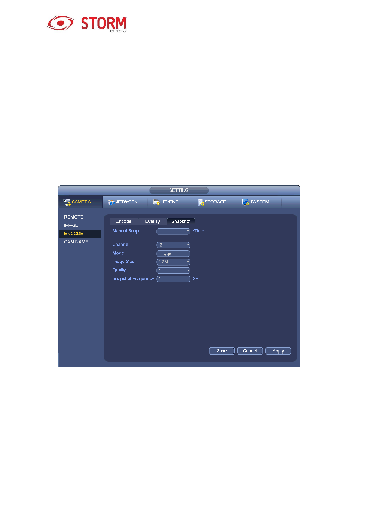
g) Click on the OK button to save the alarm recording information.
3.8.4.2 Alarm Snapshot
a) Please refer to Steps a) through c) of chapter 3.8.3.2 to enable timing snapshot.
b) From the Main Menu → Setting → Storage → Schedule you can choose the Snapshot tab like
in Figure 3-66 to enable the snapshot function.
c) From the Main Menu → Setting → Event → Alarm, you will see an interface like the one in
Figure 3-65 to set the alarm parameters and enable the snapshot function.
d) Click on the Save button to save the alarm snapshot setup.
Figure 3-66
3.8.5 Manual Record/Snapshot
You need to have the proper rights to implement the following operations. Please make sure that the
HDD has been properly installed.
3.8.5.1 Manual Recording
a) Right click your mouse and select Manual Record or from the Main Menu, go to Setting →
Storage → Manual Record. The Manual Record menu is represented in Figure 3-67.
65

Tips
You can click on the Rec button on the front panel (if possible) to go to the Manual Record interface.
Figure 3-67
b) Check the box here to select the Manual Record channel(s). You will notice that the
corresponding indicator light(s) on the front panel will be On.
Channel: It displays all the channels of the device.
Manual: It has the highest priority. It enables the corresponding channel to record no matter what
period is applied in the recording setup. Now the system is recording a general file.
Auto: The system enables the automatic recording function as you have defined it in the chapter
3.8.2 schedule interface (General/Motion Detect/Alarm).
Stop: This stops the current channel Record/Snapshot no matter what time period is applied in the
recording setup.
All: Check the All box to select all the channels.
c) Click on the OK button to complete the Manual Record setup.
66

3.8.5.2 Manual Snapshot
Click on this button in the preview control bar and you can snapshot from 1 to 5 picture(s). From the
Main Menu → Setting → Camera → Encode → Snapshot, you can configure the number of snapshots.
You can go to chapter 3.9 to view the snapshot picture.
3.8.6 Holiday Record/Snapshot
This is where you will configure the holiday recording or the snapshot schedule. Please note that the
holiday record/snapshot setup has a higher priority than the regular date record/snapshot setup.
3.8.6.1 Holiday Record
a) From the Main Menu → Setting → System → General, you will be directed to the following
interface. See Figure 3-68.
Figure 3-68
b) Click on the Add New Holidays button and an interface like the one in Figure 3-69 will appear.
Here you can also define a Holiday Name, the Repeat Mode, the Start and End Times, etc.
67

Figure 3-69
c) Click on the Add button to complete the Holiday setup. Now you can enable the holiday setup
and then click on the Apply button.
d) From the Main Menu → Setting → Storage → Schedule, you will be directed to the Schedule
interface like in Figure 3-70. Here you will be able to set the Period and the Record Type for the
Holiday. Refer to chapter 3.8.2.1 for more details regarding the configuration.
Figure 3-70
68

e) Click on the OK button to configure the holiday recording.
3.8.6.2 Holiday Snapshot
You must begin by defining the Holiday. Please refer to steps a) through c) of chapter 3.8.6.1.
From the Main Menu → Setting → Storage → Schedule, you can go to the Schedule interface like in
Figure 3-70. Click on the Holiday function to define the snapshot period.
Set the Holiday Snapshot Type to Trigger/Regular. Refer to chapter 3.8.2.2 or chapter 3.8.3.2.
3.8.7 Other Record/Snapshot
For Motion Detect & Alarm recording or snapshot please refer to chapter 3.8.4.
For Video Loss or Tampering recording or snapshot please refer to chapter 3.8.3.
3.9 Playback and Search
3.9.1 Real-Time Playback
Please refer to chapter 3.6.2 for real-time playback information.
3.9.2 Search Interface
From the Main Menu → Search or do a right-click with your mouse on the Preview interface, then select
the Search item. The interface will be like the one in Figure 3-71.
Figure 3-71
69

SN
Name
Function
1
Display Window
This is where the searched image or file will be displayed.
Supports playback on 1/4/9/16 windows.
2
Search Type
Here you can select to search the image or the recorded file.
You can select to playback from the read-write HDD, from peripheral
device or from HDD redundancy.
Before you choose to play from the peripheral device, please connect the
corresponding peripheral device. You can view all the recorded files of the
root directory of the peripheral device. Click on the Browse button and
select the file you want to play.
Important
HDD redundancy does not support picture backup function, but it
supports picture playback function. You can select to play from
redundancy HDD if there are pictures on the redundancy HDD.
3
Calendar
The blue highlighted date means there is an image or file.
In any playback mode, click on the date you want to see and you will see
the corresponding recorded file trace in the time bar.
4
Playback Mode
and Channel
Selection Panel
Playback mode:1/4/9/16. (It may vary due to different series.)
o In 1-window playback mode: you can select 1-X channels (X depends
on the number of channel in the device).
o In 4-window playback mode: you can select 4 channels according to
your requirement.
o In 9-window playback mode, you can switch between the channels 1-8,
9-16, etc.
o In 16-window playback mode, you can switch between the channels 1-
16, 17-32, etc.
The time bar will change once you modify the playback mode or the
channel option.
Please refer to the following table for more details.
70

5
Card Number
Search
The card number search interface is shown below. Here you can view the
card number/field setup bar. You can implement an Advanced Search. The
current series product supports this function.
6
Mark File List
Button
Click it to go to the Mark File List interface. You can view all the marked
information of the current channel according to the time. Please refer to
chapter 3.9.2.3 for more details. Please note only the product with this icon
supports the Mark File List function.
7
File List Switch
Button
Double click it to view the image/recording file list of the current day.
The file list displays the first channel of the recorded file.
The system can display a maximum of 128 files at a time. Use the arrows
│and │ or the mouse to view the file. Select one item, then double
click the mouse or click the ENTER button to playback.
You can input the period in the following interface to begin an accurate
search.
File type:R — regular record; A — external alarm record;M — Motion
detect record.
Locked file. Click the file you want to lock and click the button to
lock it. The file you locked will not be overwritten.
Search locked file: Click the button to view the locked file.
Return: Click button , system goes back to the calendar and channel
setup interface.
8 Playback
Control Panel
►/
Play/Pause
There are three ways for you to begin playback:
Press the Play button;
Double click the desired period on the time bar;
Double click the item in the file list.
In slow play mode, click the Playback Control Panel to switch between
play/pause.
■ Stop
Backward Play
71
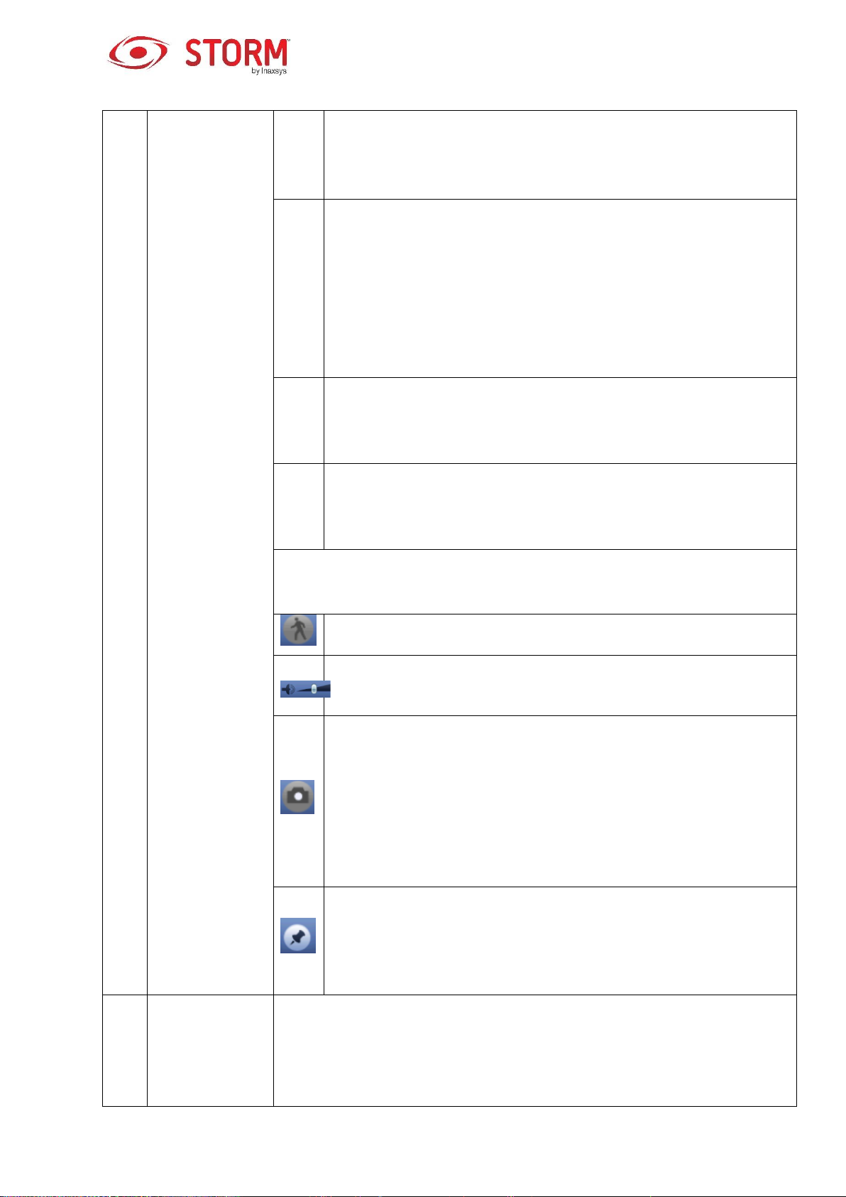
In normal play mode, click on this button and the file begins backward
play. Click it again to pause the current playback.
In backward play mode, click ►/ to restore the normal playback.
│/
│
In the Playback mode, click on this button to play the next or the
previous section. You can click on it continuously when you are
watching files from the same channel.
In Normal play mode, when you pause the current playback, you can
click on these buttons, │ and │, to begin frame by frame playback.
In frame by frame playback mode, click ►/ to restore normal
playback.
►
Slow Play
In Playback mode, click this button to realize the various slow play
modes such as slow play 1, slow play 2, etc.
Fast Forward
In Playback mode, click this button to realize the various fast play
modes such as fast play 1, fast play 2, etc.
Note
The actual play speed is related to the software version.
Smart Search
The volume of the playback
Click on this Snapshot button in the full-screen mode and the system
will snapshot 1 picture.
The system supports a customized snapshot saved path. Connect the
peripheral device first, click on the snapshot button in the full-screen
mode, then select or create a path. Click on the Start button and the
snapshot picture can now be saved to the specified path.
Marking button
Please note this function is for some series products only. Make sure
there is a mark button in the playback control panel.
You can refer to chapter 3.9.2.3 for detailed information.
9
Time Bar
It is to display the record type and its period in current search criteria.
In 4-window playback mode, there are corresponding four time bars. In
the other playback mode, there is only a one-time bar.
72

Use the mouse to click one point of the color zone in the time bar, system
begins playback.
The time bar is beginning with 0 o'clock when you are setting the
configuration. The time bar zooms in the period of the current playback
time when you are playing the file.
The green color stands for the regular record file. The red color stands for
the external alarm record file. The yellow stands for the motion detect
record file.
10
Time Bar Unit
The option includes: 24H, 12H, 1H and 30M. The smaller the unit, the
larger the zoom rate. You can accurately set the time in the time bar
to playback a specific recording.
11
Backup
Select the file(s) you want to backup from the file list. You can check the
files from the list, then click on the Backup button to see the backup
menu. The system supports a customized path setup. After selecting or
creating a new folder, click on the Start button to begin the backup
operation. The recorded file(s) will be saved in the specified folder.
If you check the file again you can cancel the current selection. The
system can display a maximum of 32 files from one channel.
For one device, if a backup is already in process, you can’t start a new
backup operation.
12
Clip
This function is to edit the file.
Play the file you want to edit and then click on this button when you want
to edit it. You can see the corresponding scroll bar in the time bar of the
corresponding channel. You can adjust the scroll bar or input the
accurate time to set the file’s end time.
Once edited, you can click on the Clip button again to edit the second
period. You can see the slide bar restore to its previous position.
Click on the Backup button after clipping and save the current contents in
a new file.
You can Clip for one channel or multiple-channel. The multiple-channel
Clip operation is similar with the one-channel operation.
73

Note
The system supports a maximum of 1024 files backed up at the same
time.
You can’t operate the Clip function if there is a file that has been checked
in the file list.
13
Record Type
In any play mode, the time bar will change once you modify the search type.
Other Functions
14
Smart Search
When the system is playing, you can select a zone in the window to
begin a Smart Search. Click on the motion detection button to begin
playback.
Once the motion detection playback has begun, click on the button
again to stop the current motion detection file playback.
There is no motion detection zone by default.
If you select to playback another file in the file list, the system will switch
to motion detection playback of the other file.
During motion detection playback, you can’t execute operations such as
change the time bar, begin backward playback or frame by frame
playback.
Please refer to chapter 3.9.2.1 Smart Search for more details.
15
Other Channels
Play
Synchronization
Switch during
Playback
When playing the file, click on the channel’s number button and the system
will switch to playing the same period of the selected channel.
16
Digital Zoom
When the system is in full-screen Playback mode, left click the mouse in
the screen. Drag your mouse in the screen to select a section and then left
click with your mouse to realize a digital zoom. You can right click mouse
to exit.
17
Manually
Switch Channel
during Playback
During the file playback process, you can switch to another channel via the
dropdown list or by rolling the ball on the mouse.
This function won’t work if there is no recorded file or if the system is in
Smart Search.
74

Note
All the operations here (such as playback speed, channel, time and progress) are related to the
version of the hardware. Some NVRs do not support certain functions or playback speeds.
3.9.2.1 Smart Search
During the multiple-channel playback mode, double click one channel and then click the button,
system begins smart search. System supports 396(22*18 PAL) and 330(22*15 NTSC) zones. Please left
click mouse to select smart search zones. See Figure 3-72.
Figure 3-72
Click this button and you will be redirected to the Smart Search playback. Click it again and the
system will stop the smart search playback.
Important
The system does not support motion detection zone setup while in full-screen mode.
During the multiple-channel playback, the system will stop the playback of all other channels if you
implement a one-channel smart search.
3.9.2.2 Accurate Playback by Time
Select the recordings from one day, click on the list and you will be redirected to the file list interface. You
can then input a time in the top right corner to search the recordings by time. See the image on the left
side in Figure 3-73. For example, if you input the time 11:00.00 and then click on the Search button
75

, you will be able to view all the recorded files after 11:00.00 (the recordings will include the current
time). In the image located on the right side in Figure 3-73, you can double-click a file name to playback.
Note
After you’ve searched the files, the system will implement the Accurate Playback function once
you click on the Play button for the first time.
The system does not support Accurate Playback for pictures.
The system supports both synchronized playback and non-synchronized playback. The
synchronized playback supports all channels and the non-synchronized playback only supports
Accurate Playback of the currently selected channel.
Figure 3-73
3.9.2.3 Mark Playback
Please make sure the device you purchased supports this function. You can use this function
only if you can see the Mark Playback icon in the Search interface (Figure 3-71).
When you playback a recording, you can mark the recording when there is important information. After
the playback, you can use the time or the Mark key words to search this same recording and then play it.
It is very easy for you to access important video information.
Add Mark
When the system is in playback, click this Mark button and you will see the following interface like in
Figure 3-74.
76

Figure 3-74
Playback Mark
During the 1-window playback mode, click the Mark File List button in Figure 3-71 to go to the Mark
File List interface. Double click one marked fil and playback will begin the marked time.
Play Before Marked Time
This is where you configure the playback to begin from X seconds prior to the marked time.
Note
Usually, the system can playback a recording X seconds before if there is such a file recorded. Otherwise,
the system plays back from the moment where such a recording actually exists.
Marks Manager
Click on the Marks Manager button in the Search interface (Figure 3-71) to get the following
interface like in Figure 3-75. By default, the system can manage all the recording’s marked information for
the current channel. You can view all the marked information for the current channel according to the time.
Figure 3-75
77

Modify
Double click one marked item and the system will display a dialog box where you can change the marked
information. You can only change the Mark name here.
Delete
Here you can check the marked item you would like to delete and then click on the Delete button to remove
this marked item.
Note
When you are in the Marks Manager interface, the system will pause the current playback. The
system will resume playback only after you have exited this interface.
If the marked file you want to playback has been removed, the system will begin playback from the
first file in the list.
3.9.3 Picture Playback
a) From the Main Menu → Search or by doing a right click with your mouse in the Preview interface,
you will be redirected to an interface like in Figure 3-71.
b) In the top right corner, you can check the box for Pictures and then select a playback interval.
c) Please refer to chapter 3.9.2 to select the Picture you want to view.
3.10 Backup
3.10.1 File Backup
In this interface, you can backup recorded files to a USB device. You must connect a USB burner, a USB
device or a portable HDD, etc. to your device.
a) From the Main Menu → Backup, you will be redirected to a Backup interface like in Figure 3-76.
78

Figure 3-76
b) Select a Backup device, then configure the channel, file start time and file end time.
c) Click on the Add button and the system will begin its search. All files that match up to the search
will be listed like in the figure below. The System automatically calculates the space used and
what remains (free). See Figure 3-77.
d) The system will only backup files that have a check mark √ in front of the channel name. You can
use the Fn or Cancel button to delete the check mark √ located after the file’s serial number.
e) Click on the Backup button and the selected files will be backed up. A processing bar will appear
for your reference.
f) When the system has completed the backup, a dialog box will appear signaling that the backup
was successful.
79
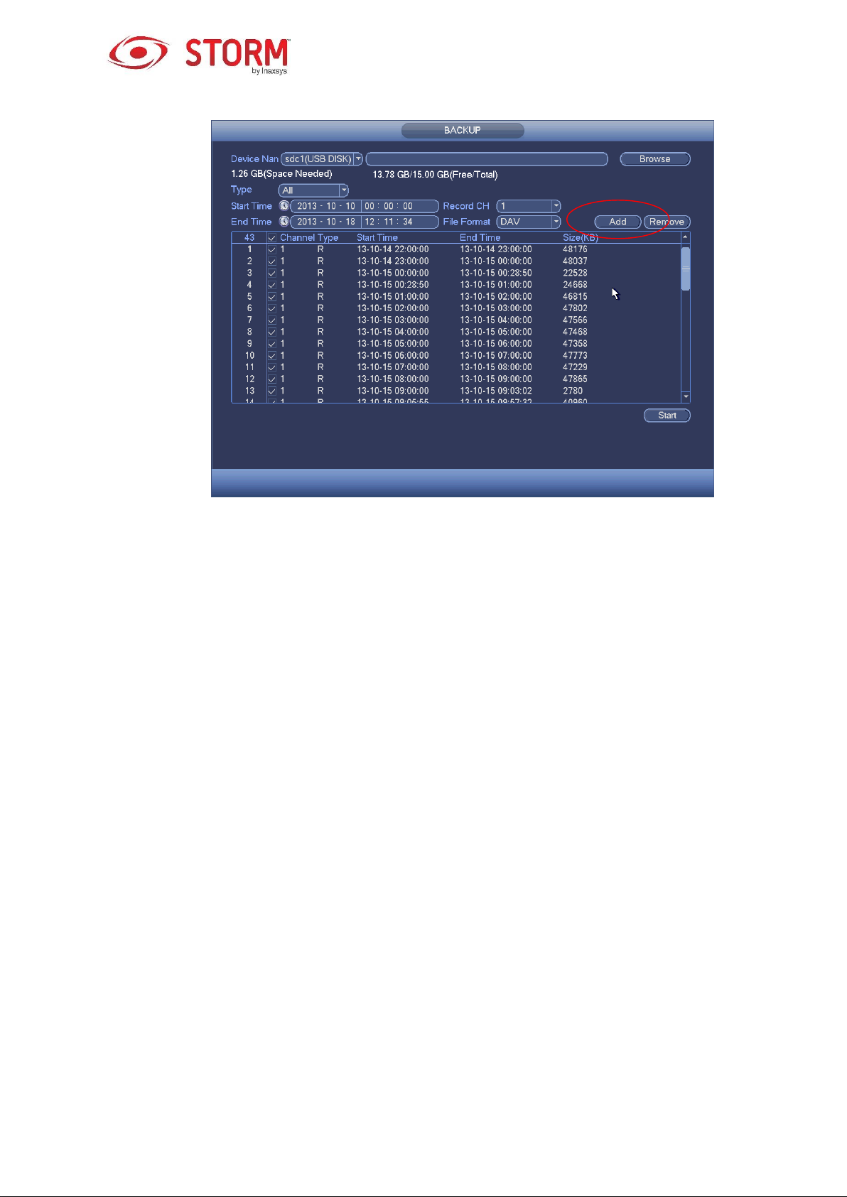
Figure 3-77
Note
During the backup process, you can click on the ESC button to exit the current interface to
execute other operations (only for with some products). The system will not stop the backup
process.
The file name format is usually: Channel Number + Recording Type + Time. In the file name,
the YDM format is Y+M+D+H+M+S. The file extension name is .dav.
3.10.2 Import/Export
This function allows you to copy the system’s current configuration to other devices. It also supports the
following functions: import, create new folder, delete folder, etc.
From the Main Menu → Setting → System → Import/Export, you will see the configuration file backup
interface like in Figure 3-78.
80

Figure 3-78
Export: You must first connect the peripheral device and then go to the following interface. Click
on the Export button and you will see the a corresponding “Config_Time” folder. Double-click on this
folder to view the backup files.
Import: Here you can import the configuration files from the peripheral device to the current device.
You need to select a folder first. Then you will see a dialog box that will ask you to select a folder.
A new dialog box will pop up if there is no configuration file in the current folder. Once the import is
successful, the system will need to reboot in order to activate the new configuration.
Format: Click on the Format button and a dialog box will pop up for you to confirm the current
operation. The system will begin the formatting process after you have clicked on the OK button.
Note
The system can’t open the configuration backup interface while there is a backup operation in
process.
The system refreshes the device when you go to the configuration backup interface and sets the
current directory as the root directory for the peripheral device.
81

If you go to the configuration backup interface first and then insert the peripheral device, make sure
to click on the Refresh button to see the newly added device.
3.10.3 Backup Log
a) From the Main Menu → Info → Log, the following interface will appear. See Figure 3-79.
Figure 3-79
b) Select the log Types, define the Start Time and the End Time, then click on the Search button and
you will see the logging time and event information. Click on this icon to view the detailed
logging information.
c) Select the logging items you want to save and then click on the Backup button. You can select a
folder in which to save them. Click on the Start button to backup and a dialog box will pop up once
the backup process is finished.
3.10.4 USB Device Auto Pop-up
Once the USB device is connected, the system can automatically detect it and the following dialog box
will pop up. This device allows you to conveniently backup a file, a log, a configuration or upgrade the
system. See Figure 3-80. For more information on the following topics you can refer to chapter 3.10.1 File
82

Backup, chapter 3.10.3 Backup Log, chapter 3.10.2 Import/Export and chapter 3.9.2 Search.
Figure 3-80
3.11 Alarm
3.11.1 Detect Alarm
In the Main Menu, go to Setting then to Detect and you will see the Motion Detect interface like in
Figure 3-81. There are three detection types: motion detection, video loss, tampering.
3.11.1.1 Motion Detection
After analyzing the video, the system can generate a motion detection alarm when the detected movement
signal has reached the sensitivity you had configured in this interface.
The detection interface is like the one shown in Figure 3-81.
Event Type: From the dropdown list you can select a motion detection type.
Channel: Select a channel from the dropdown list to configure the motion detection function.
Enable: Check this box to enable the motion detection function.
Region: Click on the Setup button and an interface like the one in Figure 3-82 will appear. Here
you can set a motion detection zone. You can configure up to four zones. Select a zone number,
then left drag the mouse to select the zone. The color of the zone displays different detection
zones. You can click on the Fn button to switch between the Arm and Disarm modes. In the Arm
mode, you can click on the direction arrows to move the green rectangle to define the motion
83

detection zone. Remember to click on the Save button to save the current setup. Once you have
completed the configuration, click on the ENTER button to exit the current setup. If you click on the
ESC button to exit the Region setup interface, the system will not save your detection zone setup.
Sensitivity: The system supports 6 sensitivity levels. The sixth level has the highest sensitivity.
Anti-dither: Here you can set an anti-dither time. The value may range from 5 to 600 seconds.
The anti-dither time refers to the duration of recording after the alarm signal. It can be seen as a
continued activation of alarm signals such as the buzzer, tour, PTZ activation, snapshot, channel
recording. The Stay time here does not include the Latch time. During an alarm, the alarm signal
can activate an anti-dither time if the system detects the local alarm again. The screen prompt, the
alarm upload, the email, etc. will not be activated. For example, if you set the anti-dither time to 10
seconds, you can see that each activation may last 10 seconds once the local alarm is activated.
During this process, if the system detects another local alarm signal 5 seconds into the anti-dither
time, then the buzzer, the tour, the PTZ activation, the snapshot, the recording of the channel will
all restart for another 10 seconds while the screen prompt, the alarm upload and the email will not
be activated again. After the 10 seconds, if the system detects another alarm signal, it can generate
an alarm since the anti-dither time is expired.
Period: Click on the Setup button and you will see an interface like the one in Figure 3-84. Here
you can set the motion detection period. The system only enables the motion detection function
during the specified periods. This is not for video loss or video tampering. There are two ways for
you to set periods and the system only supports 6 periods in one day.
o In Figure 3-84, select this icon for several dates. All the checked dates can be edited at the
same time. Now the icon will appear as such . Click on this button to delete a recording
type from one period.
o In Figure 3-84. Click on this button located after a date or a holiday and an interface like the
one in Figure 3-85 will appear. There are four recording types: regular, motion detection (MD), alarm,
MD & alarm.
Alarm Output: When an alarm occurs, the system enables the peripheral alarm devices.
Latch: When motion detection is completed, the system will automatically delay the detection for a
specified period of time. The value may range from 1-300 seconds.
84

Show Message: The system can pop up a message to notify you in the local host screen if you
have enabled this function.
Alarm Upload: The system can upload the alarm signal to the network (including to the alarm
centre) if you have enabled this function.
Send Email: The system can send out an email to alert you when an alarm occurs.
Record Channel: The system automatically activates the motion detection channel(s) to record
once an alarm occurs. Make sure you have configured the MD recording in the Schedule interface
(Main Menu → Setting → Schedule) and the Recording Schedule in the Manual Record interface
(Main Menu → Advanced → Manual Record).
PTZ Activation: Here you can set the PTZ movements for when an alarm occurs, such as go to
preset, tour and pattern. Click on the Setup button to see the interface like the one shown in Figure
3-83X.
Record Delay: The system can delay recording for a specific period of time after an alarm has
ended. The value may range from 10 to 300 seconds.
Tour: Here you can enable the Tour function when an alarm occurs. This system supports a one-
window tour.
Snapshot: You can enable this function so the system snaps a picture when a motion detection
alarm occurs.
Video Matrix: Check this box to enable this function. When an alarm occurs, SPOT OUT port
displays the device’s video output. It displays video (1-window tour) from the alarm activation
channel you have selected in the Record Channel.
Buzzer: Check this box to enable this function. The buzzer will then beep when an alarm
occurs.
Once the configuration is completed, click on the Save button and the system will go back to the previous
menu.
Note
In the motion detection mode, you can not use copy/paste to configure a channel since the video in each
channel may not be the same.
85
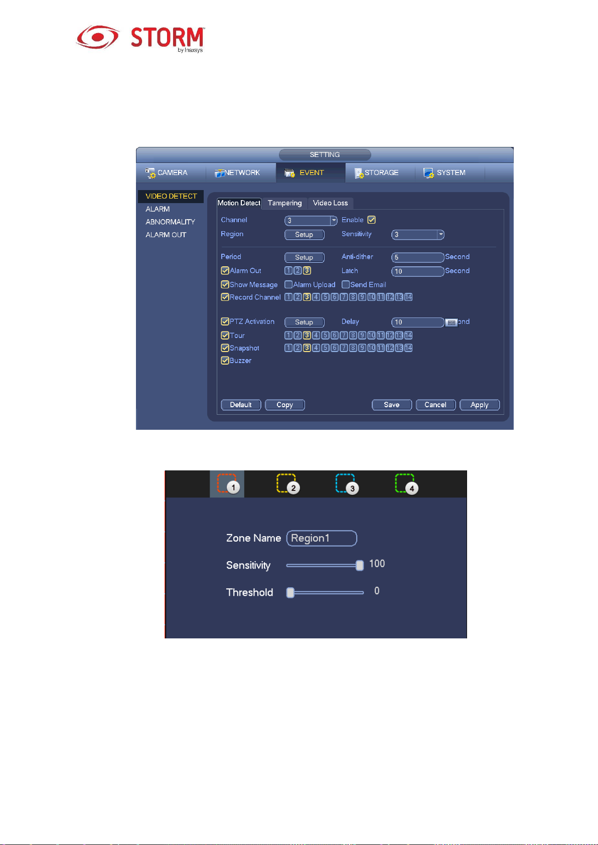
In Figure 3-82, you can left-click your mouse and then drag it to configure a region for motion detection.
Click on Fn to switch between Arm/Disarm motion detection. Once completed, click on the Enter button
to exit.
Figure 3-81
Figure 3-82
86

Figure 3-83
Figure 3-84
87

Figure 3-85
The Motion Detection only has a relationship with the Sensitivity and the Region setups. It has no
relationship with any other setups.
3.11.1.2 Tampering
When someone intentionally masks the lens or the output video is in one-color due to the
environment’s light changing, the system can alert you to ensure video continuity. The Tampering
interface is represented in Figure 3-86. You can enable the Alarm Output or the Show Message
functions for when a tampering alarm occurs.
Sensitivity: The value ranges from 1 to 6 and mainly concerns the brightness. The level 6 has a
higher sensitivity than the level 1. The default setup is a level 3 sensitivity.
Tips
You can enable the Preset/Tour/Pattern operations for when video loss occurs.
Please refer to chapter 3.11.1.1 Motion Detection for more details.
Note
In the Detect interface, the copy/paste function is only valid for the same Type. Consequently,
you can’t copy a channel’s setup from Video Loss mode to Tampering mode.
About the Default function: Since the detection channel and the detection type may not be the
same, the system can only restore the default setup for the current detection type. For example,
if you click on the Default button in the Tampering interface, you can only restore the tampering’s
default setup. It does not work for other detection types.
88

The system only enables the tampering function during the periods of time you have defined here.
It does not work for motion detection, nor for video loss types.
Figure 3-86
3.11.1.3 Video Loss
In Figure 3-81, select Video Loss from the Type list. You will see an interface like the one in Figure
3-87. This function allows you to be advised when video loss has occurred. You can enable the alarm
output channel and then enable the Show Message function. Refer to chapter 3.11.1.1Motion Detect
for more details.
Tips
You can enable preset/tour/pattern operations for when video loss occurs.
89

Figure 3-87
3.11.2 Alarm Output
From Main Menu → Setting → Event → Alarm Output to see an interface like the one in Figure 3-88.
This is where you will configure an alarm output: Auto/Manual/Stop.
Click on the OK button of the alarm reset to clear all the alarm output statuses.
Figure 3-88
90
 Loading...