

Inaxsys Standalone DVR Quick Start Manual

Standalone DVR Quick Start Guide
Version 1.0.0

i
Table of Contents
1 Hardware Installation and Connection....................................................................... 1
1.1 Check Unpacked DVR ...................................................................................... 1
1.2 About Front Panel and Rear Panel .................................................................. 1
1.3 After Remove the Chassis ................................................................................ 1
1.4 HDD Installation ................................................................................................. 1
1.4.1 HDD Calculation ................................................................................ 1
1.4.2 HDD Installation ................................................................................ 2
1.5 Rack Installation ................................................................................................ 4
1.6 Front Panel ......................................................................................................... 4
1.7 Rear Panel ......................................................................................................... 4
1.8 Connection Sample ................................ ........................................................... 5
1.9 Alarm Input and Output Connection ................................................................ 6
1.9.1 Alarm Input and Output Details ......................................................... 7
1.9.2 Alarm Input Port ................................................................................ 7
1.9.3 Alarm Output Port.............................................................................. 8
2 Overview of Navigation and Controls ........................................................................ 9
2.1 Boot up & Shut Down ........................................................................................ 9
2.1.1 Boot up .............................................................................................. 9
2.1.2 Shut Down ......................................................................................... 9
2.1.3 Auto Resume after Power Failure ................................................... 10
2.1.4 Replace Button Battery ................................................................... 10
2.2 Change Password ........................................................................................... 10
2.3 Startup Wizard ................................................................................................. 11
2.4 Preview ............................................................................................................. 13
2.5 Realtime Playback (Instant Playback) ........................................................... 13
2.6 Manual Record................................................................................................. 14

ii
2.7 Search & Playback .......................................................................................... 15
2.8 Schedule ........................................................................................................... 16
2.9 Network............................................................................................................. 17
2.10 PTZ ................................................................................................................ 18
2.10.1 PTZ Setup ................................ ....................................................... 18
2.10.2 PTZ Operation ................................................................................. 19
2.10.3 Coaxial Control ................................................................................ 20
2.11 Channel Type ............................................................................................... 21
2.12 Remote Device ............................................................................................. 23
3 Web Operation ........................................................................................................... 25
3.1 Network Connection ........................................................................................ 25
3.2 Login ................................................................................................................. 25
3.3 Main Window.................................................................................................... 25
3.3.1 LAN Login ....................................................................................... 25
3.3.2 WAN Login ...................................................................................... 26

iii
Welcome
Thank you for purchasing our DVR!
This quick start guide will help you become familiar with our DVR in a very short time.
Before installation and operation, please read the following safeguard and warning carefully!
Important Safeguard and Warning
1.Electrical safety
All installation and operation here should conform to your local electrical safety codes.
The product must be grounded to reduce the risk of electric shock.
We assume no liability or responsibility for all the fires or electrical shock caused by improper
handling or installation.
2.Transportation security
Heavy stress, violent vibration or water splash are not allowed during transportation, storage and
installation.
3.Installation
Keep upwards. Handle with care.
Do not apply power to the DVR before completing installation.
Do not place objects on the DVR.
4.Qualified engineers needed
All the examination and repair work should be done by the qualified service engineers.
We are not liable for any problems caused by unauthorized modifications or attempted repair.
5.Environment
The DVR should be installed in a cool, dry place away from direct sunlight, inflammable,
explosive substances and etc.
6. Accessories
Be sure to use all the accessories recommended by manufacturer.
Before installation, please open the package and check all the components are included:
Contact your local retailer ASAP if something is missing in your package.
7. Lithium battery
Improper battery use may result in fire, explosion, or personal injury!
When replace the battery, please make sure you are using the same model!
Caution
FOR YOUR DEVICE SAFETY, PLEASE CHANGE SYSTEM DEFAULT PASSWORD AFTER
YOU FIRST LOGIN IN!

1
1 Hardware Installation and Connection
Note: All the installation and operations here should conform to your local
electric safety rules.
1.1 Check Unpacked DVR
When you receive the DVR from the forwarding agent, please check whether there is any visible
damage. The protective materials used for the package of the DVR can protect most accidental
clashes during transportation. Then you can open the box to check the accessories.
Please check the items in accordance with the list. (Remote control is optional). Finally you can
remove the protective film of the DVR.
Note
Remote control is not a standard accessory and it is not included in the accessory bag.
1.2 About Front Panel and Rear Panel
For detailed information of the function keys in the front panel and the ports in the rear panel,
please refer to the User’s Manual included in the resource CD.
The model label in the front panel is very important; please check according to your purchase
order.
The label in the rear panel is very important too. Usually we need you to represent the serial
number when we provide the service after sales.
1.3 After Remove the Chassis
Please check the data cable, power cable, COM cable and main boar cable connection is secure
or not.
1.4 HDD Installation
1.4.1 HDD Calculation
Calculate total capacity needed by each DVR according to video recording (video recording type
and video file storage time).
Step 1: According to Formula (1) to calculate storage capacity
i
q
that is the capacity of each
channel needed for each hour, unit Mbyte.
102436008 iidq
(1)
In the formula:
i
d
means the bit rate, unit Kbit/s
Step 2: After video time requirement is confirmed, according to Formula (2) to calculate the
storage capacity
i
m
, which is storage of each channel needed unit Mbyte.
i
m
=
i
q
×
i
h
×
i
D
(2)
In the formula:
i
h
means the recording time for each day (hour)

2
i
D
means number of days for which the video shall be kept
Step 3: According to Formula (3) to calculate total capacity (accumulation)
T
q
that is needed for
all channels in the DVR during scheduled video recording.
c
i
iT
mq
1
(3)
In the formula: cmeans total number of channels in one DVR
Step 4: According to Formula (4) to calculate total capacity (accumulation)
T
q
that is needed for
all channels in DVR during alarm video recording (including motion detection).
c
i
iT
mq
1
×a% (4)
In the formula:a% means alarm occurrence rate
You can refer to the following sheet for the file size in one hour per channel. (All the data listed
below are for reference only.)
Bit stream
size(max)
File size
Bit stream size
(max)
File size
96K
42M
128K
56M
160K
70M
192K
84M
224K
98M
256K
112M
320K
140M
384K
168M
448K
196M
512K
225M
640K
281M
768K
337M
896K
393M
1024K
450M
1280K
562M
1536K
675M
1792K
787M
2048K
900M
3072Kbps
1350M
4096K
1800M
6144Kbps
2700M
8192Kbps
3600M
Note
All information listed in the above sheet for reference only. We are not reliable for any
damage or loss resulting from it.
For the space marked by the HDD manufacturer, 1K=1000, while for the computer OS,
1K=1024. So, the space recognized by the computer system is less than the marked space
on the HDD. Please pay attention to it.
All HDD space marked by the HDD manufacturer is shown as below: 1T=1000G, 1G=1000M,
1M=1000K, 1K=1000.
All HDD space marked by the HDD manufacturer shall become the computer OS space after
the corresponding calculation. For example:
1T(marked by the HDD manufacturer)=1000G/(1.024*1.024*1.024)=931G(OS space),
500G=500G/(1.024*1.024*1.024)=465G
1.4.2 HDD Installation
Important
3
Shut down the device and unplug the power cable before you install the HDD.
Always use the HDD for the surveillance product recommended by the manufacture.
All figurers listed below for reference only. Slight difference may be found on the
front or rear panel.
Please note the following contents are based on our 2U/3U series product. For
detailed operation instruction of other series products, please refer to the User’s
Manual included in the resources CD.
You can refer to the User’s Manual for recommended HDD brand. Please follow the instructions
below to install hard disk. This series DVR max supports 8 SATA HDDs. Please use HDD of
7200rpm or higher.
1.4.2.1 2U Series
① Loosen the screws of the upper cover and remove
the cover.
② Fix the HDD on the bracket. If you want to install the HDD
on the bottom bracket, you need to remove the top bracket
first.
③ Connect one end of the HDD data cable to one
HDD.
④ Connect the other end of the HDD data cable to the
mainboard.
⑤ Connect the power cable to the HDD.
⑥ Put the cover back and then fix.
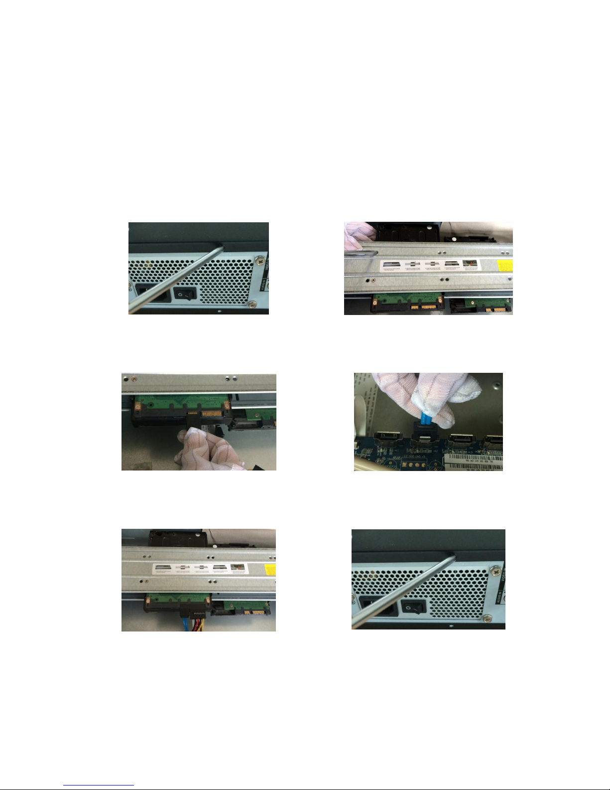
1.4.2.2 3U Series

4
① Remove the HDD box from the device.
② Put the HDD to the box and then use the screws to
secure.
③ Insert the HDD box to the device. Please make sure
the HDD box handle is up in case it collides with the front
panel.
④ After you inserted the HDD box, put the handle back.
Important
You can connect the HDD data cable and the power cable first and then fix the HDD in the
device.
Please pay attention to the front cover. It adopts the vertical sliding design. You need to
push the clip first and then put down.
1.5 Rack Installation
Please note this installation mode is for 1.5U/2U series product.
Please follow the steps listed below.
Use twelve screws to fix the unit
Please make sure the indoor temperature is below 35℃ (95°f).
Please make sure there is 15cm (6 inches) space around the device to guarantee sound
ventilation.
Please install from the bottom to the top.
If there are more accessories connected in the rack, please take precaution measures in
case the rack power is overload.
1.6 Front Panel
For detailed operation instruction, please refer to the User’s Manual included in the
resources CD.
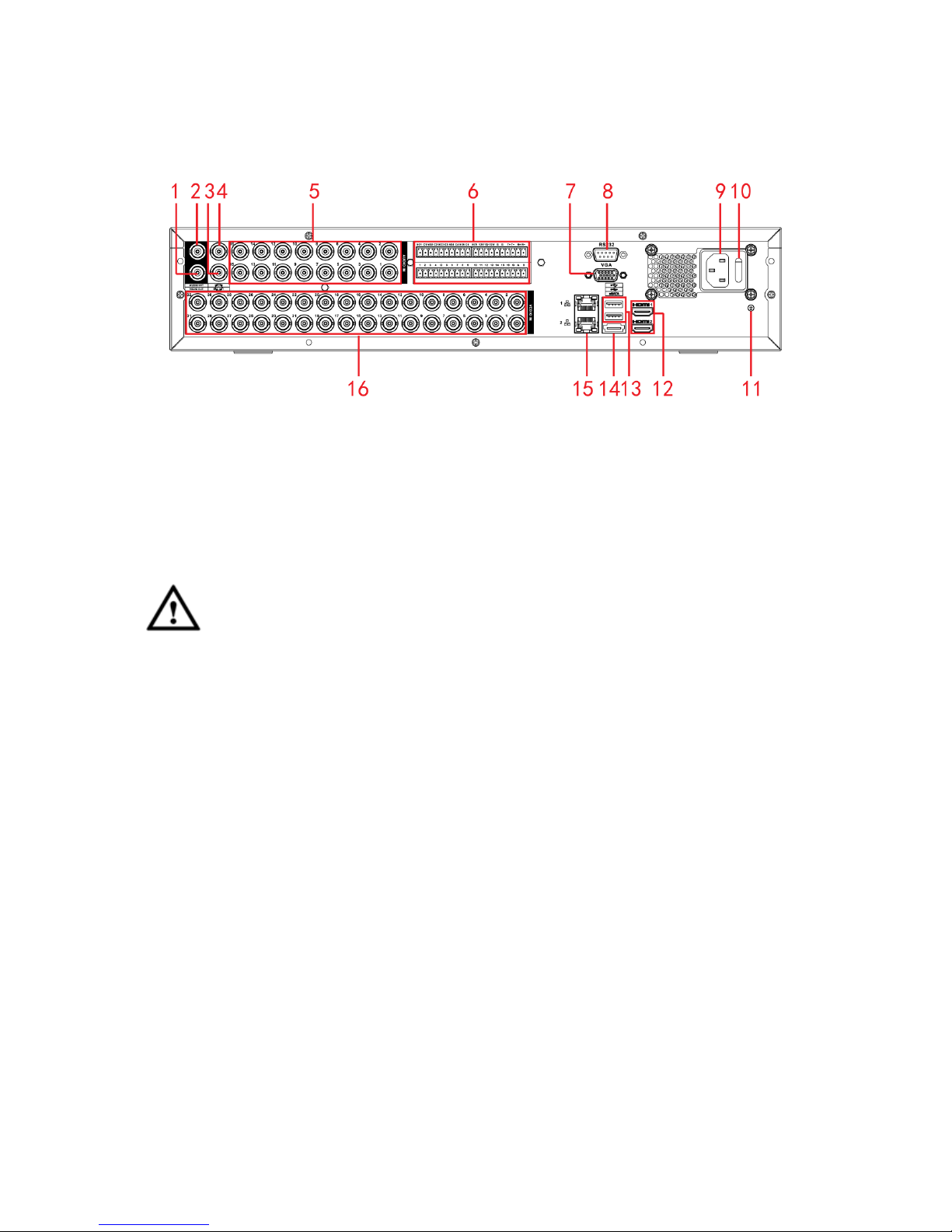
1.7 Rear Panel
5
Please note the following contents are based on our 2U series product. For detailed
operation instruction of other series products, please refer to the User’s Manual included
in the resources CD.
This series DVR rear panel is shown as below. See Figure 1-1.
Figure 1-1
Please refer to the following sheet for detailed information.
1. Video output
2. Audio output
3. Bidirectional talk
output
4. Bidirectional talk
input
5. Audio input
6. Alarm input/alarm
output
7. Video VGA output
8. RS-232 port
9. Power socket
10. Power switch
11. GND
12. HDMI port
13. USB port
14. eSATA port
15. Network port
16. Video input
Important
When connect the Ethernet port, please use crossover cable to connect the PC and use the
straight cable to connect to the switch or router.
1.8 Connection Sample
Please note the following contents are based on our 2U series product. For detailed
operation instruction of other series products, please refer to the User’s Manual included
in the resources CD.
Please refer to Figure 1-2 for connection sample.
The following figure is based on the 16-channel series product.
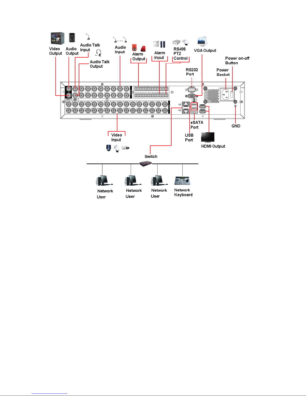
6
Figure 1-2
1.9 Alarm Input and Output Connection
Please read the followings before connecting.
1. Alarm input
a. Please make sure alarm input mode is grounding alarm input.
b. Grounding signal is needed for alarm input.
c. Alarm input needs the low level voltage signal.
d. Alarm input mode can be either NC (normal Open) or NO (Normal Close)
e. When you are connecting two DVRs or you are connecting one DVR and one other device,
please use a relay to separate them,
2. Alarm output
The alarm output port should not be connected to high power load directly (It shall be less than
1A) to avoid high current which may result in relay damage. Please use the co contactor to
realize the connection between the alarm output port and the load.
3. How to connect PTZ decoder
a. Ensure the decoder has the same grounding with DVR, otherwise you may not control the PTZ.
Shielded twisted wire is recommended and the shielded layer is used to connect to the grounding.
 Loading...