

Inaxsys IN-DO2MIRVSLL, IN-DO4MF, IN-DO1MIRF, IN-DO4M36A, IN-DO2MIRF Installation Manual
...
Outdoor Dome
Flat Surfaced Ceiling Mounted
Exterior Dome (Face Down)
Installation Guide
For Models:
IN-DO2MIRVSLL, IN-DO4MF, IN-DO4M36A, IN-DO1MIRF, IN-DO2MIRF,
IN-DO3MIRF, IN-DO5MIRF, IN-DO1MIRV, IN-DO2MIRV, IN-DO3MIRV &
IN-DO5MIRV

Installation Guide
Table of Contents
Installation Procedures ..................................................... 3
Step 1: Drill the Holes ................................................................................ 3
Step 2: Open the Dome Cover .................................................................. 4
Step 3: Prepare for Waterproof Installation ............................................. 5
Waterproof Solution with Naked Cable ................................................... 6
Waterproof Solution with Conduit ............................................................ 8
Step 4: Install the Camera to the Ceiling ............................................... 12
Step 5: Connect the Cable(s) .................................................................. 13
Step 6: Access the Camera Live View .................................................... 14
Step 7: Adjust the Viewing Angle and Focus ........................................ 14
Step 8: Close the Dome Cover ................................................................ 15
Appendices ....................................................................... 16
Accessing the Camera Live View ........................................................... 16
Focus and Viewing Angle Adjustments ................................................. 24
Safety Information ............................................................ 30
8272 Pascal Gagnon Saint-Leonard, Quebec, Canada H1P 1Y4 www.inaxsys.com
Installation Guide
Installation Procedures
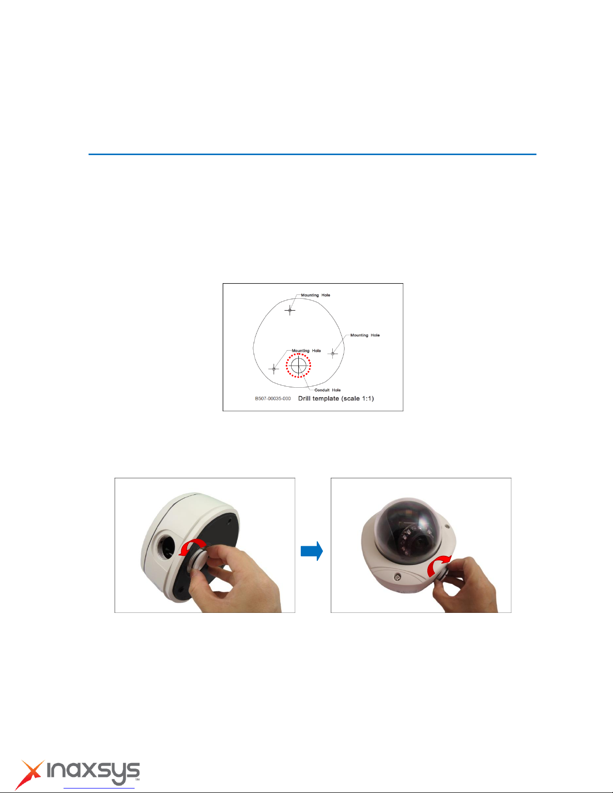
Step 1: Drill the Holes
1. Using the supplied drill template, mark the screw holes location on the ceiling, then drill the holes
and insert the plastic plugs.
2. Determine how the cables will be routed: pass through the ceiling or along the ceiling.
If the cables will pass through the ceiling:
a. Mark and drill the conduit hole location on the ceiling as shown on the drill template.
b. Remove the metal cap covering the bottom conduit hole of the camera, and attach
the cap to the side conduit hole to close it. Route the network cable to pass this hole
from the ceiling.
If the cables will be routed along the ceiling, skip to the next step.
8272 Pascal Gagnon Saint-Leonard, Quebec, Canada H1P 1Y4 www.inaxsys.com
Installation Guide
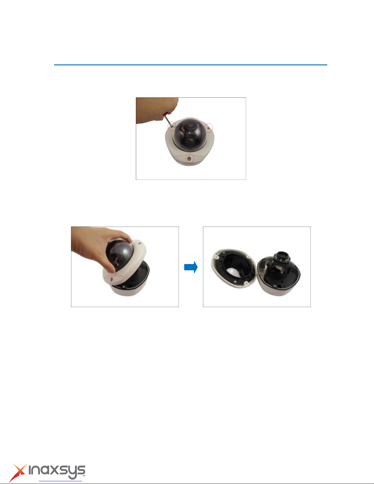
Step 2: Open the Dome Cover
1. Remove the plastic covering the camera.
2. Loosen the three (3) screws securing the dome cover.
3. Carefully lift to open the dome cover and place it on the side of the camera.
NOTE: Do not abruptly lift the dome cover; it is attached to the camera with a spring wire.
8272 Pascal Gagnon Saint-Leonard, Quebec, Canada H1P 1Y4 www.inaxsys.com
Installation Guide
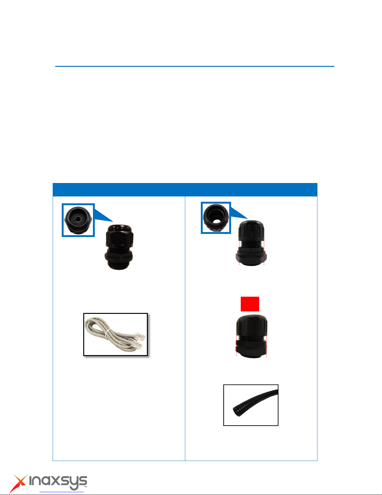
Cable Gland
Conduit Gland
For use with an Exterior-grade Ethernet
cable (not included in the package).
For use with a 3/8” flexible conduit (not
included in the package).
For use with 1/2” flexible conduit (not
included in the package)
NOTE: The bundled conduit gland may vary.
Check the conduit gland that came with your
package to determine if 3/8” or 1/2" is the
suitable flexible conduit size.
or
Step 3: Prepare for Waterproof Installation
The camera comes with two (2) glands used for waterproof installation:
Cable Gland: For use with an Exterior-grade Ethernet cable. Exterior-grade Ethernet
cables are already waterproof. Waterproof Solution with Naked Cable on page 6.
Conduit Gland: For use with a flexible conduit. This solution is recommended when an
exterior-grade Ethernet cable is not available or when other input/output devices or external
power adapter will be connected to the camera (select models only). See Waterproof
Solution with Conduit on page 8.
Determine the type of waterproof solution that is applicable to your installation requirements and
prepare the necessary accessories or purchase extra materials.
8272 Pascal Gagnon Saint-Leonard, Quebec, Canada H1P 1Y4 www.inaxsys.com
Installation Guide
Body
(with Washer)
Sealing Insert
with Claw
Clamping
Nut
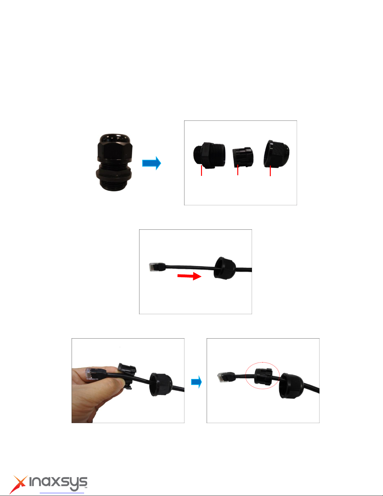
Waterproof Solution with Naked Cable
This section describes the procedures in using the bundled cable gland and an exterior-grade
Ethernet cable.
1. Disassemble the cable gland as shown below:
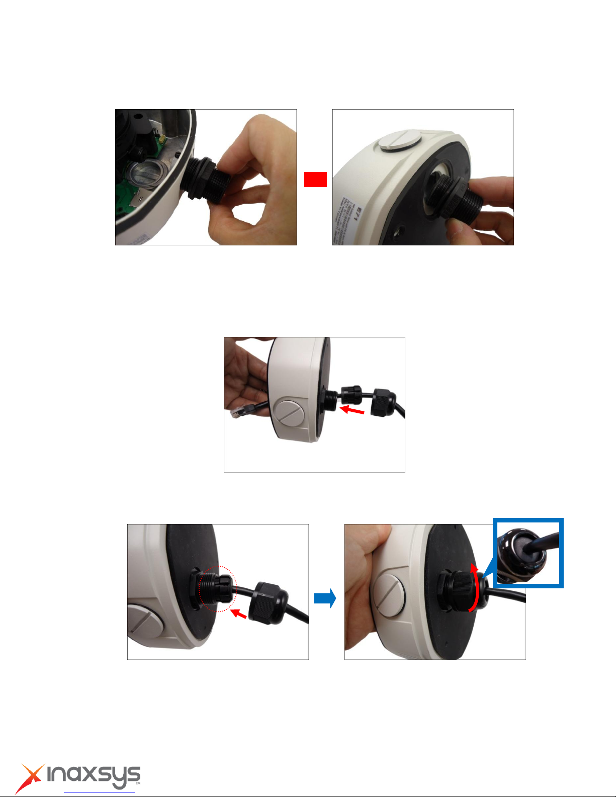
2. Insert the clamping nut into the Ethernet cable.
3. Insert the sealing insert with claw.
8272 Pascal Gagnon Saint-Leonard, Quebec, Canada H1P 1Y4 www.inaxsys.com
Installation Guide
or
4. Attach the cable gland body to the hole of the camera.
Attach to Camera Side Hole Attach to Camera Bottom Hole
5. If the cable will be routed along the surface, skip this step.
If the cable will pass through the surface, do the following:
a. Pull the network cable through the bottom conduit hole.
b. Insert the sealing insert with claw into the cable gland body and then attach the clamping nut
to complete the cable solution.
NOTE: Make sure the clamping nut is tightly attached to the cable gland body and the sealing
insert is squeezed tightly.
6. Proceed with Step 4: Install the Camera to the Ceiling on page 12.
8272 Pascal Gagnon Saint-Leonard, Quebec, Canada H1P 1Y4 www.inaxsys.com
Installation Guide
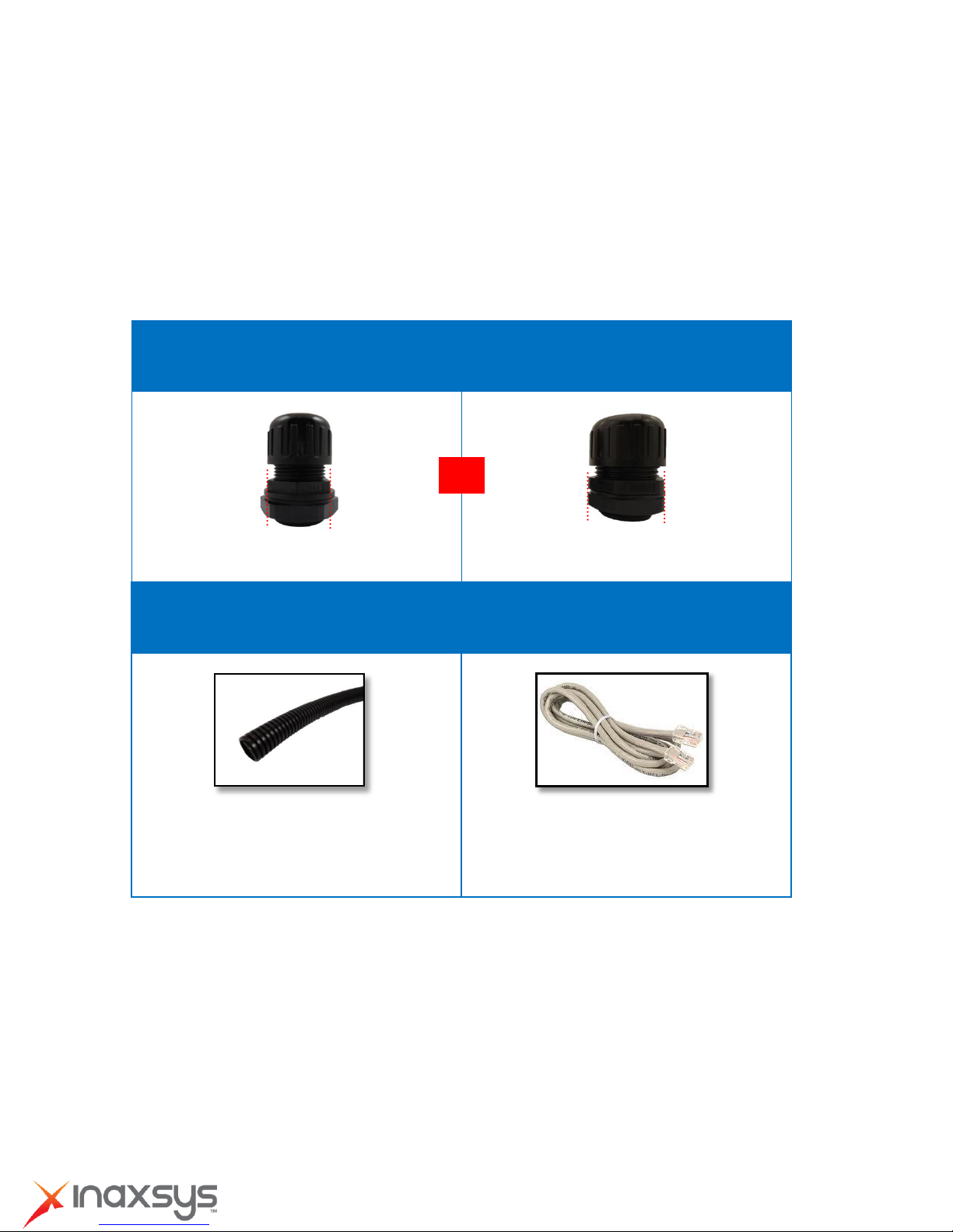
Conduit Gland
(included in the camera package)
For use with 3/8” flexible conduit
For use with 1/2” flexible conduit
Flexible Conduit
3/8” or 1/2" Trade size
(not included in the package)
Network Cable
CAT 5 or CAT 6
(not included in the package)
NOTE: The bundled conduit gland may vary.
Check the conduit gland that came with your
package to determine if 3/8” or 1/2" is the
suitable flexible conduit size.
or
Waterproof Solution with Conduit
This section describes the procedures to waterproof the cabling connections using the bundled
conduit gland and flexible conduit. This is the recommended when an exterior-grade Ethernet cable
is not available or if other input/output devices or an external power adapter will be connected to the
camera (select models only).
1. Prepare the following materials for waterproof installation:
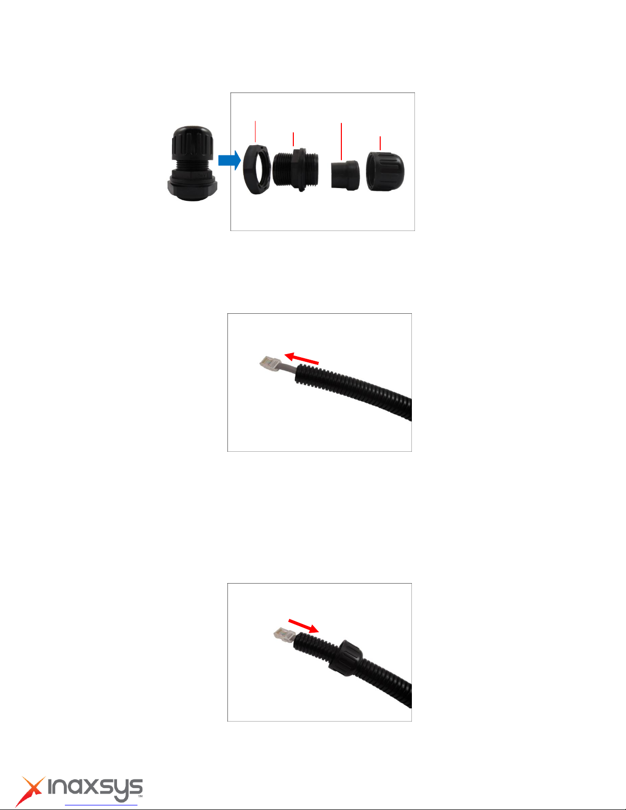
2. Disassemble the bundled conduit gland as shown below:
8272 Pascal Gagnon Saint-Leonard, Quebec, Canada H1P 1Y4 www.inaxsys.com
Installation Guide
Lock Nut
Body
Sealing Insert
Clamping Nut
NOTE: In this installation, the conduit gland body can be securely attached to the camera; therefore
the use of lock nut is not necessary. Please set the lock nut aside.
3. Pull the network cable through the flex conduit.
NOTE: For camera models that support external power adaptor, audio in/out, or digital
input/output (DI/DO) functions, route the cables without connectors through the flex conduit
together with the network cable. The connectors will be attached later after the cables pass
through the conduit hole of the camera.
4. Insert the clamping nut through the flex conduit.
8272 Pascal Gagnon Saint-Leonard, Quebec, Canada H1P 1Y4 www.inaxsys.com

Installation Guide
or
5. Insert the sealing inside and attach it at the end of the flex conduit.
6. Screw the conduit gland body to the conduit hole of the camera.
Attach to Side Conduit Hole Attach to Bottom Conduit Hole
7. If the cable will be routed along the ceiling, skip to step 8.
If the cable will pass through the ceiling, do the following:
a. Pull the network cable and other cables (if any) through the bottom conduit hole.
8272 Pascal Gagnon Saint-Leonard, Quebec, Canada H1P 1Y4 www.inaxsys.com
 Loading...