


IN-DI2MPTZ20X AND IN-DO2MPTZ20X
Full HD Speed Dome IP Camera
01/07/2013
User’s Manual
Indoor / Outdoor
Ver. 1.0
1

Table of Contents
1. Overview ................................................................................................................................ 3
1.1 Features ...................................................................................................................... 3
1.2 Package Contents ....................................................................................................... 4
1.3 Dimensions .................................................................................................................. 6
1.4 Switch / Connector Definition ....................................................................................... 7
2. Camera Cabling ..................................................................................................................... 8
2.1 Connect Power ............................................................................................................ 8
2.2 Connect Ethernet Cable ............................................................................................... 8
2.3 Apply Alarm I/O............................................................................................................ 9
2.4 Apply Audio ................................................................................................................. 9
3. System Requirements ......................................................................................................... 10
4. Access Camera ................................................................................................................... 11
5. Setup Video Resolution ...................................................................................................... 15
Appendix A: Technical Specifications....................................................................................... 16
Appendix B: Delete the Existing DC Viewer .............................................................................. 19
Appendix C: Setup Internet Security ......................................................................................... 19
Appendix D: Video Resolution ................................................................................................... 21
Quad Stream ........................................................................................................................ 21
Triple Stream ........................................................................................................................ 25
Dual Stream ......................................................................................................................... 27
Single Stream ....................................................................................................................... 28
2

1. Overview
The Full HD Speed Dome IP Camera transmits digital video and audio data using wire
connection. Live video can be monitored and recorded from window-based computer
via network.
The video encoder supports real-time H.264 Full HD resolution. Simultaneous Quad
Codecs, H.264 Baseline / Main / High Profile, MJPEG, are available for various network
applications via speeding or limited bandwidth. Better image quality and high resolution
are delivered by IP support. It eliminates the “combing” effect due to scene change and
performs more stabilized image.
With IP solution, multiple and authorized users can view the immediate image from any
location through network even using a standard web-browser. It enables users to
access and remote the camera without at specific locations.
1.1 Features
18x, 20x Optical Zoom
10x Digital Zoom
Dual Streams, Full HD real-time + D1 real-time
Quad streams, MJPEG + H.264 x 3 / H.264 x 4 support
Quad Codecs, H.264 Baseline / Main / High Profile, MJPEG
Vertical View Mode (Image rotation by 90 degrees)
Full HD Real-time Resolution
Two-way Audio Support
Removable IR Cut Filter
Motion Detection
Wide Dynamic Range
Digital Noise Reduction
3
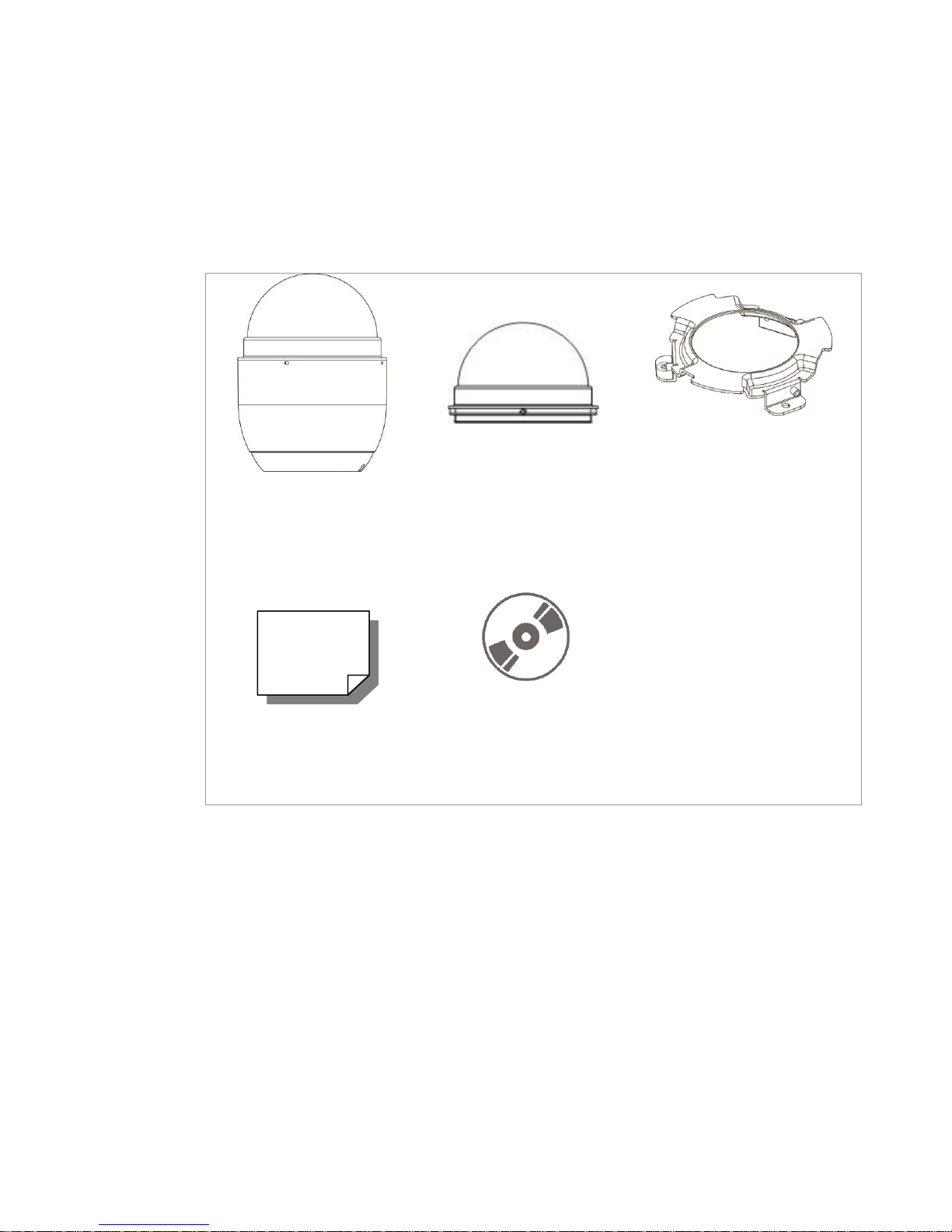
1.2 Package Contents
Camera Body
Optical Cover
Hard Ceiling Mount
M4 Screw (x5)
Plastic Anchors (x5)
Quick Guide
CD: Operation Manuals
Please check the box contains the items listed here. If any item is missing or has
defects, DO NOT install or operate the product and contact the dealer for assistance.
Indoor Dome Camera Package
4
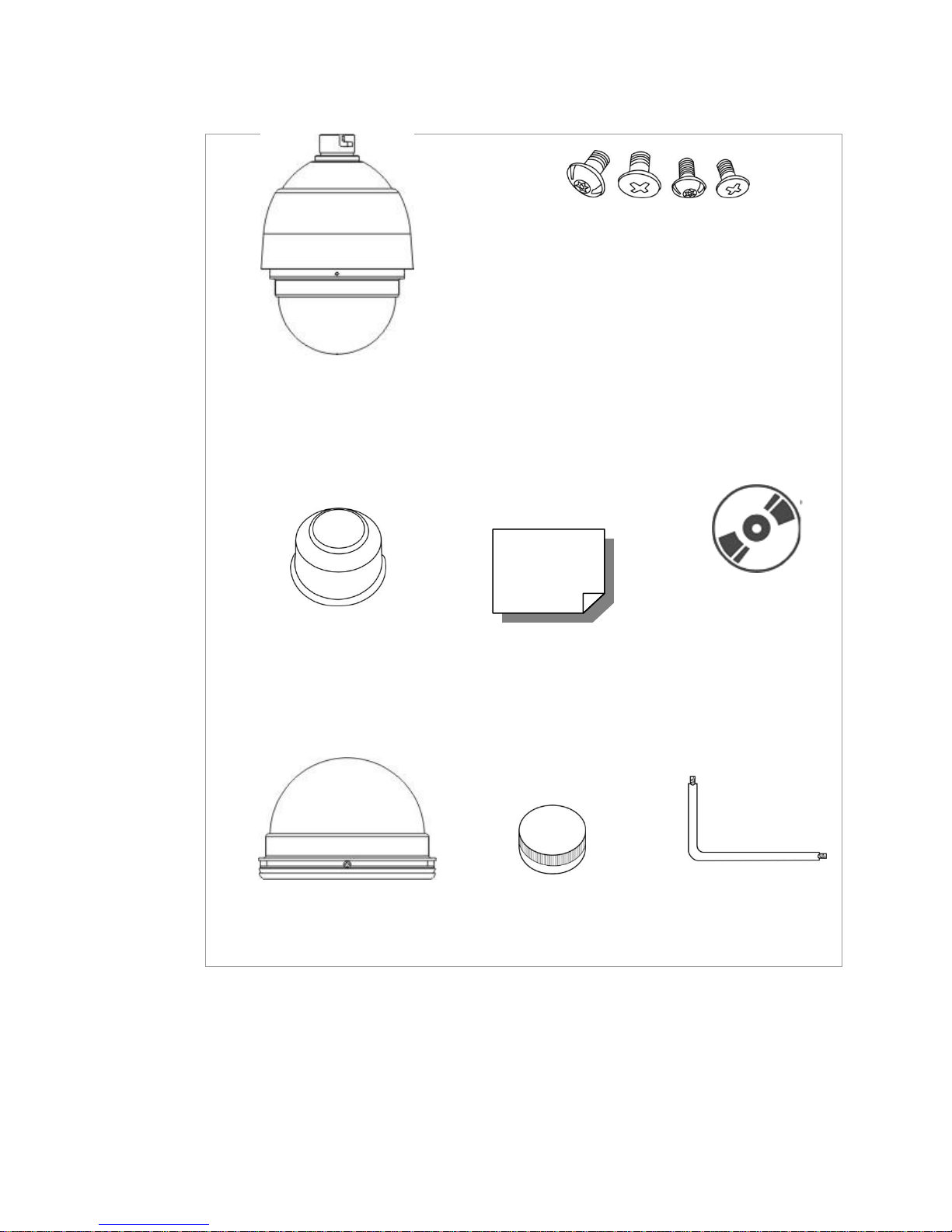
Outdoor Dome Camera Package
Dome Camera with
Outdoor Mount Kit
M3 Standard Screw (x1)
M3 Security Screw (x1)*
M5 Standard Screw (x1)
M5 Security Screw (x1)*
Waterproof Rubber
Quick Guide
CD: Operation
Manuals
Optical Cover
Lubricant
Security Torx*
*Optional: For Vandal Proof Cover only.
5
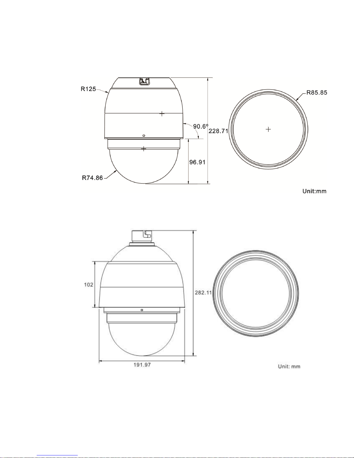
1.3 Dimensions
Indoor
Outdoor
6
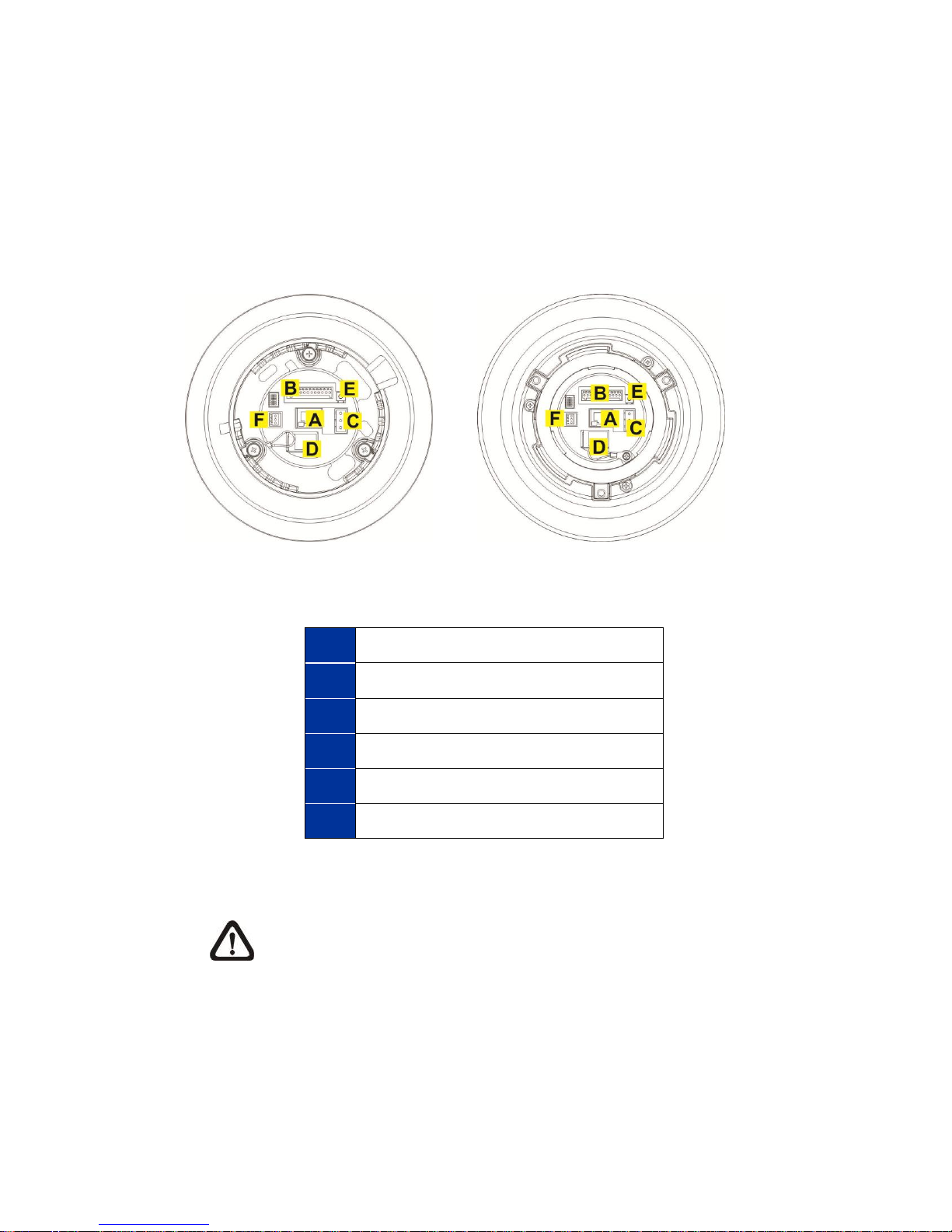
1.4 Switch / Connector Definition
A
RJ-45 Connector
B
ALARM I/O
C
Power
D
Micro SD Card Slot
E
Factory Reset Button
F
Audio I/O
There are various connectors located on the Dome Camera’s back plate as shown in
the figures below.
Please refer to the diagrams and tables accompanied with for use of each switch /
connector.
Indoor Outdoor
NOTE: DO NOT change the Network Speed Dome Camera’s
Communication Switch factory default settings.
7
2. Camera Cabling
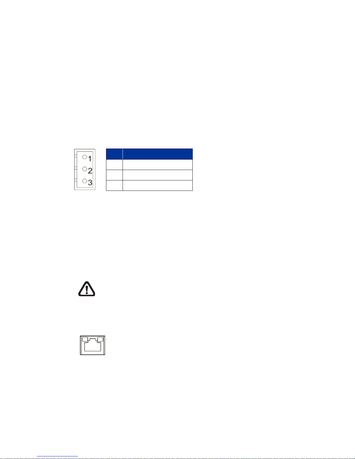
Green Link Light indicates good network connection.
Orange Activity Light flashes for network activity indication.
Pin
Definition
1
AC 24_1
2
FG 3 AC 24_2
Please follow the instructions below to complete Network Speed Dome Camera
connection.
2.1 Connect Power
Please refer to the illustrations below to connect power core through the supplied power
adaptor.
2.2 Connect Ethernet Cable
Use of Category 5 Ethernet cable is recommended for network connection; to have best
transmission quality, cable length shall not exceed 100 meters. Connect one end of the
Ethernet cable to the RJ-45 connector of the Network Speed Dome Camera, and the
other end of the cable to the network switch or PC.
NOTE: In some cases, Ethernet Crossover Cable might be needed
when connecting the Network Speed Dome Camera directly to the
PC.
Check the status of the link indicator and activity indicator LEDs. If the LEDs are unlit,
please check LAN connection.
8
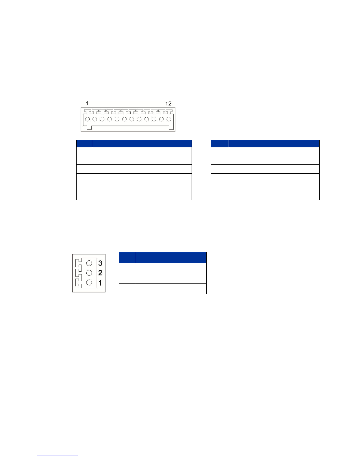
2.3 Apply Alarm I/O
Pin
Definition
Pin
Definition
1
ALARM_OUT_NO_1
7 ALARM_OUT_COM_2
2
ALARM_OUT_NC_1
8
GND
3
ALARM_OUT_COM_1
9 ALARM_IN_4
4
GND
10
ALARM_IN_3
5
ALARM_OUT_NO_2
11
ALARM_IN_2
6
ALARM_OUT_NC_2
12
ALARM_IN_1
Pin
Definition
1
LINE_OUT
2
GND
3
LINE_IN
The Network Speed Dome Camera supports 4 digital alarm inputs and 2 digital alarm
outputs. Please make sure the alarm connections are properly wired before starting to
configure alarm related settings on this “Application” page. Please refer to the pin
definition table below for alarm system wiring.
2.4 Apply Audio
Please refer to the illustrations below to set up the audio according to the Audio pin
definition.
9

3. System Requirements
Items
Minimum Requirement
Personal Computer
1. Intel® Pentium® IV, 3 GHz or higher, Intel® Core2 Duo,
2 GHz or higher
2. 1 GB RAM or more
3. AGP graphics card 64 MB RAM, DirectDraw
Operating System
Windows VISTA / Windows XP / Windows 7
Web Browser
Internet Explorer 6.0 or later, Firefox, Chrome, Safari
Network Card
10Base-T (10 Mbps) or 100Base-TX (100 Mbps)
operation
Viewer
ActiveX control plug-in for Microsoft IE
To perform the Network Speed Dome Camera via web browser, please ensure the PC is
in good network connection, and meet system requirement as described below.
10

4. Access Camera
Login ID
Password
admin
123456
For initial access to the Network Speed Dome Camera, users can search the camera
through the installer program: DeviceSearch.exe, which can be found in “Device
Search” folder in the supplied CD.
Device Search Software Setup
Step 1: Double click on the program Device Search.exe. After its window will appear,
click on the <Device Search> button on the top side.
Step 2: The security alert window will pop up. Click on <Unblock> to continue.
Device Search
Step 3: Click on <Device Search> again, and all the finding IP devices will be listed
in the page. The Network Speed Dome Camera’s default IP address is: 192.168.0.100.
Step 4: Double click or right click and select <Browse> to access the camera directly
via web browser.
Step 5: Then the prompt window of request for entering default username and
password will appear for logging in to the Network Speed Dome Camera.
The default login ID and password for the Administrator are:
NOTE: ID and password are case sensitive.
11

NOTE: It is strongly advised that administrator’s
password be altered for the security concerns. Refer to
Full HD Speed Dome IP Camera Menu Tree for further
details.
Additionally, users can change the Network Speed Dome Camera’s network property,
either DHCP or Static IP directly in the device finding list. Refer to the following section
for changing the Network Speed Dome Camera’s network property.
Example of Changing IP Camera’s Network Property
Users can directly change a Network Speed Dome Camera’s network property, ex. from
static IP to DHCP, in the finding device list. The way to change the camera’s network
property is specified below:
Step 1: In the finding device list, click on the Network Speed Dome
Camera that is wished to change its network property. On the
selected item, right click and select <Network Setup>. Meanwhile,
record the Network Speed Dome Camera’s MAC address, for
future identification.
Step 2: The <Network Setup> page will come out. Select <DHCP>, and
click on <Apply> button down the page.
Step 3: Click on <OK> on the Note of setting change. Wait for one minute
to re-search the Network Speed Dome Camera.
Step 4: Click on the <Device Search> button to re-search all the devices.
Then select the Network Speed Dome Camera with the correct
MAC address. Double click on the IP Camera, and the login
window will come out.
Step 5: Enter User name and Password to access the Network Speed
Dome Camera.
12

Installing DC Viewer Software Online
For the initial access to the Network Speed Dome Camera, a client program, DC
Viewer, will be automatically installed to the PC when connecting to the Network Speed
Dome Camera.
If the Web browser doesn’t allow DC Viewer installation, please check the Internet
security settings or ActiveX controls and plug-ins settings (refer to Internet Security
Settings) to continue the process.
The Information Bar (just below the URL bar) may come out and ask for permission to
install the ActiveX Control for displaying video in browser. Right click on the Information
Bar and select <Install ActiveX Control…> to allow the installation. Then the security
warning window will pop up. Click on <Install> to carry on software installation.
Click on <Finish> to close the DC Viewer window when download is finished. For the
detailed software download procedure, please refer to DC Viewer Download Procedure.
NOTE: If the Live Video Pane on Home Page can not be shown for
users who have installed the DC Viewer in the PC previously.
Please refer to Upgrade the DC Viewer.
Once login to the Network Speed Dome Camera, users will see the Home page as
shown below:
13

NOTE: Refer to Full HD Speed Dome IP Camera Menu Tree for
further button / function details.
14

5. Setup Video Resolution
Users can setup Video Resolution on Video Format page of the user-friendly browserbased configuration interface.
Video Format can be found under this path: Streaming> Video Format.
The default value of Video Resolution is H.264- 1920 x 1080 (30 fps) + H.264 720 x 480
(30 fps)
For more Video Resolution combination detail, please refer to Appendix D: Video
Resolution. Click on <Save> to confirm the setting.
15

Appendix A: Technical Specifications
Items
18N1 Model
20N1 Model
Camera
Image Sensor
1/2.8" Sony Progressive CMOS
Optical Zoom
18x
20x
Digital Zoom
1 ~ 10x variable
Minimum illumination
0.05 (Color), 0.01 lux (B / W) @
F1.6
0.05 (Color), 0.01 lux (B / W) @
F1.6
Focal Length
4.7 ~ 84.6 mm
4.7 ~ 94 mm
Focus Mode
Auto / Manual
White Balance
Auto / Indoor / Outdoor / ATW / Manual
Iris Control
Auto / Manual
Electronic Shutter
1/1 ~ 1/10k sec.
AGC control
Auto / Manual
Backlight Compensation
On / Off
Operation
Pan Travel
360° endless
Tilt Travel
- 10° ~ 190°
Manual Speed
0.5° ~ 90° /s
Presets
256
Preset Accuracy
0.225°
Preset Speed
5° ~ 400° /s
Sequence
8
Auto Pan
4
Cruise
8
Privacy Mask
16
Proportional Pan & Tilt
On / Off (Pan and tilt speed proportional to zoom ratio)
16

Items
18N1 Model
20N1 Model
Resume after Power loss
Yes
Home Function
Preset / Sequence / Auto Pan / Cruise
Auto Flip
Image / Mechanical / Off
Motion Detection
On / Off
Wide Dynamic Range
On / Off
Day / Night: IR Cut Filter
Auto / Manual
Image Rotation
Flip / Mirror / Inverse / Portrait
Digital Noise Reduction
On / Off
Network
Video Compression
H.264 / MJPEG
Video Streaming
Quad Streams - H.264*4 / MJPEG + H.264*3
Video Resolution
1080P / SXGA / 720P / XGA / SVGA / D1 / VGA / CIF
Frame Rate
1080P (30 fps) + D1 (30 fps)
720P (60 fps) + CIF (60 fps)
Audio Compression
G.711 / G.726 ADPCM / AAC
Audio Streaming
Two-way Audio
Networking
10 / 100 Mb Ethernet (RJ-45)
Protocols
IPv4/v6, TCP/IP, UDP, RTP, RTSP, HTTP, HTTPS, ICMP, FTP,
SMTP, DHCP, PPPoE, UPnP, IGMP, SNMP, IEEE 802.1x, QoS,
ONVIF
Security
User Account and Password Protection
Alarm
Input
4 Sets
Output
2 Sets
Alarm Reaction
Preset / Sequence / Auto Pan / Cruise
Micro SD
microSDHC 32GB support
Supported Web Browser
Internet Explorer (6.0+) / Chrome / Firefox / Safari
17

General
Environment
Indoor / Outdoor
Operating
Temperature
Indoor
0°C ~ 40°C (32°F ~ 104°F)
Outdoor
- 40°C ~ 50°C (- 40°F ~ 122°F)
Dimension
Indoor
∅ 171.7 × 228.71 mm (∅ 6.76 × 9 in.)
Outdoor
∅ 191.97 × 282.11 mm (∅ 7.55 × 11.1 in.) w/ Sunshield
Weight
Indoor
1.6 kg (3.57 lb)
Outdoor
2.3 kg (5.11 lb) w/ Sunshield
Power Source
Indoor
802.3 at HPoE / AC 24V ± 10%
Outdoor
PoE+ (w/o Heater) / AC 24V ± 10%
Power
Consumption
Indoor
20 W
Outdoor
50 W (w/ Heater)
Regulatory
CE / FCC / RoHS / IP66 (Outdoor)
18

Appendix B: Delete the Existing DC Viewer
For users who have installed the DC Viewer in the PC previously, please first remove
the existing DC Viewer from the PC before accessing to the Network Speed Dome
Camera.
Deleting the DC Viewer
Activate <Control Panel>, and then double click on <Add or Remove Programs>. In the
<Currently installed programs> list, select <DC Viewer> and click on the button
<Remove> to uninstall the existing DC Viewer.
Deleting Temporary Internet Files
To improve browser performance, it is suggested to clean up the all the files in the
Temporary Internet Files.
The procedure is as follows:
Step 1: Click on the <Tools> tab and select the option <Internet Options>.
Step 2: Click on <Delete> button under <Browsing history> section. Then click on the
<Delete Files> button under the <Temporary Internet files> section.
Step 3: A confirmation window will pop up. Click on <Yes> to start deleting the files.
Appendix C: Setup Internet Security
If ActiveX control installation is blocked, please either set Internet security level to
default or change ActiveX controls and plug-ins settings.
Internet Security Level: Default
Step 1: Start the Internet Explorer (IE).
Step 2: Click on the <Tools> tab on the menu bar and select <Internet Options>.
Step 3: Click on the <Security> tab, and select <Internet> zone.
Step 4: Down the page, click on the <Default Level> button and click on <OK> to
confirm the setting. Close the browser window, and restart a new one later to access
the Network Speed Dome Camera.
ActiveX Controls and Plug-ins Settings
Step 1: Repeat Step 1~3 of the previous section above.
19

Step 2: Down the page, click on the <Custom Level> button to change ActiveX controls
ActiveX controls and plug-ins settings:
1. Allow previously unused ActiveX controls to run without prompt.
2. Allow Scriptlets.
3. Automatic prompting for ActiveX controls.
4. Binary and script behaviors.
5. Display video and animation on a webpage that does not use external media player.
6. Download signed ActiveX controls.
7. Download unsigned ActiveX controls.
8. Initialize and script ActiveX controls not marked as safe for scripting.
9. Run ActiveX controls and plug-ins.
10. Script ActiveX controls marked safe for scripting.
and plug-ins settings. The Security Settings window will pop up.
Step 3: Under <ActiveX controls and plug-ins>, set ALL items (as listed below) to
<Enable> or <Prompt>. Please note that the items vary by IE version.
Step 4: Click on <OK> to accept the settings and close the Security Settings window.
Step 5: Click on <OK> to close the Internet Options screen.
Step 6: Close the browser window, and restart a new one later for accessing the
Camera.
20

Appendix D: Video Resolution
H.264 + H.264 + H.264 + H.264 / MJPEG
H.264-1
H.264-2
H.264-3
H.264-4 / MJPEG
1920 x 1080 (15 fps)
1280 x 1024 (15 fps)
1280 x 720 (15 fps)
720 x 480 (15 fps)
640 x 480 (15 fps)
352 x 240 (30 fps)
800 x 600 (15 fps)
720 x 480 (30 fps)
640 x 480 (30 fps)
800 x 600 (30 fps)
352 x 240 (30 fps)
720 x 480 (15 fps)
720 x 480 (30 fps)
720 x 480 (30 fps)
640 x 480 (30 fps)
352 x 240 (30 fps)
640 x 480 (30 fps)
640 x 480 (30 fps)
352 x 240 (30 fps)
352 x 240 (30 fps)
352 x 240 (30 fps)
1280 x 720 (15 fps)
1280 x 720 (15 fps)
720 x 480 (30 fps)
640 x 480 (30 fps)
352 x 240 (30 fps)
800 x 600 (30 fps)
720 x 480 (30 fps)
640 x 480 (30 fps)
352 x 240 (30 fps)
720 x 480 (30 fps)
720 x 480 (30 fps)
640 x 480 (30 fps)
640 x 480 (30 fps)
640 x 480 (30 fps)
1280 x 720 (30 fps)
720 x 480 (30 fps)
352 x 240 (30 fps)
640 x 480 (30 fps)
352 x 240 (30 fps)
352 x 240 (30 fps)
352 x 240 (30 fps)
1024 x 768 (15 fps)
800 x 600 (30 fps)
720 x 480 (30 fps)
640 x 480 (30 fps)
720 x 480 (30 fps)
720 x 480 (30 fps)
640 x 480 (30 fps)
640 x 480 (30 fps)
640 x 480 (30 fps)
1024 x 768 (30 fps)
800 x 600 (30 fps)
352 x 240 (30 fps)
720 x 480 (30 fps)
352 x 240 (30 fps)
640 x 480 (30 fps)
352 x 240 (30 fps)
352 x 240 (30 fps)
352 x 240 (30 fps)
800 x 600 (30 fps)
800 x 600 (30 fps)
720 x 480 (30 fps)
640 x 480 (30 fps)
352 x 240 (30 fps)
720 x 480 (30 fps)
720 x 480 (30 fps)
640 x 480 (30 fps)
352 x 240 (30 fps)
640 x 480 (30 fps)
640 x 480 (30 fps)
352 x 240 (30 fps)
352 x 240 (30 fps)
352 x 240 (30 fps)
720 x 480 (30 fps)
720 x 480 (30 fps)
720 x 480 (30 fps)
640 x 480 (30 fps)
352 x 240 (30 fps)
640 x 480 (30 fps)
640 x 480 (30 fps)
352 x 240 (30 fps)
352 x 240 (30 fps)
352 x 240 (30 fps)
640 x 480 (30 fps)
640 x 480 (30 fps)
640 x 480 (30 fps)
352 x 240 (30 fps)
352 x 240 (30 fps)
352 x 240 (30 fps)
352 x 240 (30 fps)
352 x 240 (30 fps)
352 x 240 (30 fps)
Quad Stream
21

H.264 + H.264 + H.264 + H.264 / MJPEG
H.264-1
H.264-2
H.264-3
H.264-4 / MJPEG
1280 x 1024 (15 fps)
1280 x 1024 (15 fps)
1280 x 720 (15 fps)
720 x 480 (30 fps)
640 x 480 (30 fps)
1280 x 720 (30 fps)
352 x 240 (30 fps)
800 x 600 (30 fps)
720 x 480 (30 fps)
640 x 480 (30 fps)
352 x 240 (30 fps)
720 x 480 (30 fps)
720 x 480 (30 fps)
640 x 480 (30 fps)
640 x 480 (30 fps)
640 x 480 (30 fps)
1280 x 1024 (30 fps)
720 x 480 (30 fps)
352 x 240 (30 fps)
640 x 480 (30 fps)
352 x 240 (30 fps)
352 x 240 (30 fps)
352 x 240 (30 fps)
1280 x 720 (15 fps)
1280 x 720 (30 fps)
720 x 480 (30 fps)
640 x 480 (30 fps)
352 x 240 (30 fps)
1280 x 720 (30 fps)
800 x 600 (30 fps)
720 x 480 (30 fps)
640 x 480 (30 fps)
352 x 240 (30 fps)
720 x 480 (30 fps)
720 x 480 (30 fps)
640 x 480 (30 fps)
352 x 240 (30 fps)
640 x 480 (30 fps)
640 x 480 (30 fps)
352 x 240 (30 fps)
352 x 240 (30 fps)
352 x 240 (30 fps)
1024 x 768 (30 fps)
800 x 600 (30 fps)
720 x 480 (30 fps)
640 x 480 (30 fps)
352 x 240 (30 fps)
720 x 480 (30 fps)
720 x 480 (30 fps)
640 x 480 (30 fps)
352 x 240 (30 fps)
640 x 480 (30 fps)
640 x 480 (30 fps)
352 x 240 (30 fps)
800 x 600 (30 fps)
800 x 600 (30 fps)
720 x 480 (30 fps)
640 x 480 (30 fps)
720 x 480 (30 fps)
720 x 480 (30 fps)
640 x 480 (30 fps)
1280 x 1024 (30 fps)
1024 x 768 (30 fps)
352 x 240 (30 fps)
352 x 240 (30 fps)
800 x 600 (30 fps)
800 x 600 (30 fps)
352 x 240 (30 fps)
720 x 480 (30 fps)
352 x 240 (30 fps)
640 x 480 (30 fps)
640 x 480 (30 fps)
352 x 240 (30 fps)
352 x 240 (30 fps)
352 x 240 (30 fps)
720 x 480 (30 fps)
720 x 480 (30 fps)
720 x 480 (30 fps)
640 x 480 (30 fps)
352 x 240 (30 fps)
640 x 480 (30 fps)
640 x 480 (30 fps)
352 x 240 (30 fps)
352 x 240 (30 fps)
352 x 240 (30 fps)
640 x 480 (30 fps)
640 x 480 (30 fps)
640 x 480 (30 fps)
352 x 240 (30 fps)
352 x 240 (30 fps)
352 x 240 (30 fps)
352 x 240 (30 fps)
352 x 240 (30 fps)
352 x 240 (30 fps)
1280 x 720 (15 fps)
1280 x 720 (15 fps)
1280 x 720 (30 fps)
720 x 480 (30 fps)
640 x 480 (30 fps)
1280 x 720 (30 fps)
1280 x 720 (30 fps)
352 x 240 (30 fps)
800 x 600 (30 fps)
720 x 480 (30 fps)
640 x 480 (30 fps)
22

H.264 + H.264 + H.264 + H.264 / MJPEG
H.264-1
H.264-2
H.264-3
H.264-4 / MJPEG
720 x 480 (30 fps)
720 x 480 (30 fps)
640 x 480 (30 fps)
640 x 480 (30 fps)
640 x 480 (30 fps)
1024 x 768 (30 fps)
800 x 600 (30 fps)
720 x 480 (30 fps)
640 x 480 (30 fps)
H.264 + H.264 + H.264 + H.264 / MJPEG
H.264-1
H.264-2
H.264-3
H.264-4 / MJPEG
1280 x 720 (30 fps)
1280 x 720 (30 fps)
800 x 600 (30 fps)
352 x 240 (30 fps)
720 x 480 (30 fps)
352 x 240 (60 fps)
640 x 480 (30 fps)
352 x 240 (60 fps)
352 x 240 (60 fps)
352 x 240 (60 fps)
1024 x 768 (30 fps)
800 x 600 (30 fps)
352 x 240 (30 fps)
720 x 480 (30 fps)
720 x 480 (30 fps)
640 x 480 (30 fps)
352 x 240 (60 fps)
640 x 480 (30 fps)
640 x 480 (30 fps)
352 x 240 (60 fps)
352 x 240 (60 fps)
352 x 240 (60 fps)
800 x 600 (30 fps)
800 x 600 (30 fps)
720 x 480 (30 fps)
640 x 480 (30 fps)
352 x 240 (60 fps)
720 x 480 (30 fps)
720 x 480 (30 fps)
640 x 480 (60 fps)
720 x 480 (60 fps)
352 x 240 (60 fps)
640 x 480 (30 fps)
640 x 480 (60 fps)
640 x 480 (60 fps)
352 x 240 (60 fps)
800 x 600 (60 fps)
352 x 240 (60 fps)
352 x 240 (60 fps)
720 x 480 (30 fps)
720 x 480 (30 fps)
720 x 480 (60 fps)
640 x 480 (60 fps)
720 x 480 (60 fps)
352 x 240 (60 fps)
640 x 480 (30 fps)
640 x 480 (60 fps)
720 x 480 (60 fps)
640 x 480 (60 fps)
352 x 240 (60 fps)
352 x 240 (60 fps)
352 x 240 (60 fps)
640 x 480 (30 fps)
640 x 480 (30 fps)
640 x 480 (60 fps)
640 x 480 (60 fps)
640 x 480 (60 fps)
352 x 240 (60 fps)
352 x 240 (60 fps)
352 x 240 (60 fps)
352 x 240 (60 fps)
352 x 240 (60 fps)
352 x 240 (60 fps)
1024 x 768 (30 fps)
1024 x 768 (30 fps)
800 x 600 (30 fps)
720 x 480 (30 fps)
640 x 480 (30 fps)
352 x 240 (30 fps)
720 x 480 (30 fps)
720 x 480 (30 fps)
640 x 480 (30 fps)
352 x 240 (30 fps)
640 x 480 (30 fps)
640 x 480 (30 fps)
352 x 240 (30 fps)
352 x 240 (30 fps)
352 x 240 (30 fps)
800 x 600 (30 fps)
800 x 600 (30 fps)
720 x 480 (30 fps)
640 x 480 (30 fps)
352 x 240 (30 fps)
720 x 480 (30 fps)
720 x 480 (30 fps)
640 x 480 (30 fps)
352 x 240 (30 fps)
640 x 480 (30 fps)
640 x 480 (30 fps)
23

H.264 + H.264 + H.264 + H.264 / MJPEG
H.264-1
H.264-2
H.264-3
H.264-4 / MJPEG
352 x 240 (30 fps)
352 x 240 (30 fps)
352 x 240 (30 fps)
720 x 480 (30 fps)
720 x 480 (30 fps)
720 x 480 (30 fps)
640 x 480 (30 fps)
352 x 240 (30 fps)
640 x 480 (30 fps)
640 x 480 (30 fps)
352 x 240 (30 fps)
352 x 240 (30 fps)
352 x 240 (30 fps)
640 x 480 (30 fps)
640 x 480 (30 fps)
640 x 480 (30 fps)
352 x 240 (30 fps)
352 x 240 (30 fps)
352 x 240 (30 fps)
352 x 240 (30 fps)
352 x 240 (30 fps)
352 x 240 (30 fps)
H.264 + H.264 + H.264 + H.264 / MJPEG
H.264-1
H.264-2
H.264-3
H.264-4 / MJPEG
800 x
600 (30
fps)
800 x 600 (30 fps)
800 x 600 (60 fps)
352 x 240 (60 fps)
720 x 480 (60 fps)
720 x 480 (60 fps)
640 x 480 (60 fps)
640 x 480 (60 fps)
640 x 480 (60 fps)
800 x 600
(60 fps)
720 x 480
(60 fps)
352 x 240
(60 fps)
640 x 480 (60 fps)
352 x 240 (60 fps)
720 x 480
(30 fps)
720 x 480
(60 fps)
720 x 480
(60 fps)
640 x 480 (60 fps)
720 x 480 (60 fps)
720 x 480 (60 fps)
352 x 240 (60 fps)
640 x 480 (60 fps)
640 x 480 (60 fps)
352 x 240 (60 fps)
640 x 480 (60 fps)
640 x 480 (60 fps)
640 x 480 (60 fps)
800 x
600 (60
fps)
800 x 600 (60 fps)
352 x 240 (60 fps)
352 x 240 (60 fps)
720 x 480 (60 fps)
352 x 240 (60 fps)
352 x 240 (60 fps)
640 x 480 (60 fps)
640 x 480 (60 fps)
352 x 240 (60 fps)
352 x 240 (60 fps)
352 x 240 (60 fps)
352 x 240 (60 fps)
352 x 240 (60 fps)
352 x 240 (60 fps)
720 x
480 (30
fps)
720 x 480
(60 fps)
720 x 480 (60 fps)
720 x 480 (60 fps)
640 x 480 (60 fps)
640 x 480 (60 fps)
640 x 480 (60 fps)
640 x 480 (60 fps)
640 x 480 (60 fps)
640 x 480 (60 fps)
720 x
480 (60
fps)
720 x 480
(60 fps)
720 x 480 (60 fps)
352 x 240 (60 fps)
640 x 480 (60 fps)
352 x 240 (60 fps)
352 x 240 (60 fps)
352 x 240 (60 fps)
640 x 480 (60 fps)
640 x 480 (60 fps)
352 x 240 (60 fps)
352 x 240 (30 fps)
352 x 240 (60 fps)
352 x 240 (60 fps)
352 x 240 (30 fps)
352 x 240 (60 fps)
640 x 480 (30 fps)
640 x 480 (60 fps)
640 x 480 (60 fps)
640 x 480 (60 fps)
640 x 480 (60 fps)
640 x 480 (60 fps)
640 x 480 (60 fps)
352 x 240 (60 fps)
352 x 240 (60 fps)
352 x 240 (60 fps)
352 x 240 (60 fps)
352 x 240 (60 fps)
352 x 240 (60 fps)
352 x 240 (60 fps)
352 x 240 (60 fps)
352 x 240 (60 fps)
352 x 240 (60 fps)
24

Triple Stream
H.264-1 + H.264-2 + H.264-3 / MJPEG
H.264-1
H.264-2
H.264-3 / MJPEG
1920 x 1080 (15 fps)
1280 x 1024 (15 fps)
1280 x 720 (15 fps)
800 x 600 (30 fps)
720 x 480 (30 fps)
640 x 480 (30 fps)
352 x 240 (30 fps)
1280 x 720 (15 fps)
1280 x 720 (30 fps)
800 x 600 (30 fps)
1280 x 720 (30 fps)
720 x 480 (30 fps)
640 x 480 (30 fps)
352 x 240 (30 fps)
1024 x 768 (30 fps)
800 x 600 (30 fps)
720 x 480 (30 fps)
640 x 480 (30 fps)
352 x 240 (30 fps)
800 x 600 (30 fps)
800 x 600 (30 fps)
720 x 480 (30 fps)
640 x 480 (30 fps)
352 x 240 (30 fps)
720 x 480 (30 fps)
720 x 480 (30 fps)
640 x 480 (30 fps)
352 x 240 (30 fps)
640 x 480 (30 fps)
640 x 480 (30 fps)
352 x 240 (30 fps)
1920 x 1080 (30 fps)
352 x 240 (30 fps)
352 x 240 (30 fps)
1280 x 1024 (15 fps)
1280 x 1024 (15 fps)
1280 x 720 (30 fps)
800 x 600 (30 fps)
1280 x 1024 (30 fps)
720 x 480 (30 fps)
640 x 480 (30 fps)
352 x 240 (30 fps)
1280 x 720 (15 fps)
1280 x 720 (30 fps)
1280 x 720 (30 fps)
800 x 600 (30 fps)
720 x 480 (30 fps)
640 x 480 (30 fps)
1024 x 768 (30 fps)
800 x 600 (30 fps)
720 x 480 (30 fps)
1280 x 1024 (30 fps)
1280 x 720 (30 fps)
352 x 240 (30 fps)
1024 x 768 (30 fps)
640 x 480 (30 fps)
352 x 240 (30 fps)
800 x 600 (30 fps)
800 x 600 (30 fps)
720 x 480 (30 fps)
640 x 480 (30 fps)
352 x 240 (30 fps)
720 x 480 (30 fps)
720 x 480 (30 fps)
640 x 480 (30 fps)
352 x 240 (30 fps)
640 x 480 (30 fps)
640 x 480 (30 fps)
352 x 240 (30 fps)
352 x 240 (30 fps)
352 x 240 (30 fps)
1280 x 720 (15 fps)
1280 x 720 (30 fps)
1280 x 720 (30 fps)
25

H.264-1 + H.264-2 + H.264-3 / MJPEG
H.264-1
H.264-2
H.264-3 / MJPEG
1280 x 720 (30 fps)
1280 x 720 (30 fps)
800 x 600 (30 fps)
720 x 480 (30 fps)
640 x 480 (30 fps)
1280 x 720 (60 fps)
352 x 240 (60 fps)
1024 x 768 (30 fps)
800 x 600 (30 fps)
720 x 480 (30 fps)
640 x 480 (30 fps)
352 x 240 (30 fps)
800 x 600 (30 fps)
800 x 600 (60 fps)
720 x 480 (60 fps)
640 x 480 (60 fps)
800 x 600 (60 fps)
352 x 240 (60 fps)
720 x 480 (60 fps)
720 x 480 (60 fps)
640 x 480 (60 fps)
352 x 240 (60 fps)
640 x 480 (60 fps)
640 x 480 (60 fps)
352 x 240 (60 fps)
1280 x 720 (60 fps)
352 x 240 (60 fps)
352 x 240 (60 fps)
1024 x 768 (30 fps)
1024 x 768 (30 fps)
800 x 600 (30 fps)
720 x 480 (30 fps)
640 x 480 (30 fps)
352 x 240 (30 fps)
800 x 600 (30 fps)
800 x 600 (30 fps)
720 x 480 (30 fps)
640 x 480 (30 fps)
352 x 240 (30 fps)
720 x 480 (30 fps)
720 x 480 (30 fps)
640 x 480 (30 fps)
352 x 240 (30 fps)
640 x 480 (30 fps)
640 x 480 (30 fps)
352 x 240 (30 fps)
352 x 240 (30 fps)
352 x 240 (30 fps)
800 x 600 (30 fps)
800 x 600 (60 fps)
800 x 600 (60 fps)
720 x 480 (60 fps)
640 x 480 (60 fps)
800 x 600 (60 fps)
800 x 600 (60 fps)
352 x 240 (60 fps)
720 x 480 (60 fps)
720 x 480 (60 fps)
640 x 480 (60 fps)
352 x 240 (60 fps)
640 x 480 (60 fps)
640 x 480 (60 fps)
352 x 240 (60 fps)
352 x 240 (60 fps)
352 x 240 (60 fps)
720 x 480 (60 fps)
720 x 480 (60 fps)
720 x 480 (60 fps)
640 x 480 (60 fps)
352 x 240 (60 fps)
640 x 480 (60 fps)
640 x 480 (60 fps)
352 x 240 (60 fps)
352 x 240 (60 fps)
352 x 240 (60 fps)
640 x 480 (60 fps)
640 x 480 (60 fps)
640 x 480 (60 fps)
352 x 240 (60 fps)
352 x 240 (60 fps)
352 x 240 (60 fps)
352 x 240 (60 fps)
352 x 240 (60 fps)
352 x 240 (60 fps)
26

Dual Stream
H.264-1 + H.264-2 / MJPEG
H.264-1
H.264-2 / MJPEG
BNC SUPPORT
1920 x 1080 (15 fps)
1920 x 1080 (15 fps)
-
1280 x 1024 (30 fps)
-
1280 x 720 (30 fps)
-
1024 x 768 (30 fps)
-
800 x 600 (30 fps)
-
1920 x 1080 (30 fps)
720 x 480 (30 fps)
-
640 x 480 (30 fps)
-
352 x 240 (30 fps)
-
1280 x 1024 (30 fps)
1280 x 1024 (15 fps)
-
1280 x 720 (30 fps)
-
1024 x 768 (30 fps)
-
800 x 600 (30 fps)
-
720 x 480 (30 fps)
-
640 x 480 (30 fps)
-
352 x 240 (30 fps)
-
1280 x 720 (30 fps)
1280 x 720 (30 fps)
-
1024 x 768 (30 fps)
-
800 x 600 (60 fps)
-
720 x 480 (60 fps)
-
640 x 480 (60 fps)
-
1280 x 720 (60 fps)
352 x 240 (60 fps)
-
1024 x 768 (30 fps)
1024 x 768 (30 fps)
-
800 x 600 (30 fps)
-
720 x 480 (30 fps)
-
640 x 480 (30 fps)
-
352 x 240 (30 fps)
-
800 x 600 (60 fps)
800 x 600 (60 fps)
-
720 x 480 (60 fps)
-
27

H.264-1 + H.264-2 / MJPEG
H.264-1
H.264-2 / MJPEG
BNC SUPPORT
640 x 480 (60 fps)
-
352 x 240 (60 fps)
-
720 x 480 (60 fps)
720 x 480 (60 fps)
-
640 x 480 (60 fps)
-
352 x 240 (60 fps)
-
640 x 480 (60 fps)
640 x 480 (60 fps)
-
352 x 240 (60 fps)
-
352 x 240 (60 fps)
352 x 240 (60 fps)
-
H.264 Only
BNC SUPPORT
1920 x 1080 (30 fps) Low Latency
-
1920 x 1080 (30 fps)
-
1280 x 1024 (30 fps)
-
1280 x 720 (60 fps)
-
1024 x 768 (30 fps)
-
800 x 600 (60 fps)
-
720 x 480 (60 fps)
-
640 x 480 (60 fps)
352 x 240 (60 fps)
-
MJPEG Only
BNC SUPPORT
1920 x 1080 (30 fps)
-
1280 x 1024 (30 fps)
-
1280 x 720 (30 fps)
-
1024 x 768 (30 fps)
-
800 x 600 (60 fps)
-
720 x 480 (60 fps)
-
640 x 480 (60 fps)
-
352 x 240 (60 fps)
-
Single Stream
28
 Loading...