

Inax SATIS DV-218-VH-W, SATIS GBC-941SU-AY Installation Manual
PCW-1115-W(08100)
Installation Manual
DV-218-VH-W (GBC-941SU-AY)
●Use an receptacle with a maximum rating of AC 220 V and 1200 W.
●The length of the power cord is 1.2 m.
Install the receptacle so that it is within reach of the power cord and high enough from the oor so that water won't splash on it.
●Be sure to install a ground (Class 3 ground terminal construction).
* Ask an electrical contractor to install the wiring.
* Do not insert the power plug in the receptacle until installation is completely nished.
Doing so may cause system failure.
Power Supply
●
Be sure to connect the water supply parts to the potable water line.
If surface water, industrial water or well water is used, it may cause
deterioration of electrical and mechanical parts and lead to accidents.
Water Supply
Water Pressure
●The minimum operating water pressure when 20 L/min. is
owing is 0.1 MPa {1.0 kgf/cm2} or greater. The maximum water
pressure is 0.75 MPa {7.5 kgf/cm2} under hydrostatic pressure.
Even if other xtures are used simultaneously, a supply water
pressure of 0.1 MPa {1.0 kgf/cm2} or greater and less than 0.75
MPa {7.5kgf/cm2} is required. If this minimum water pressure is
not reached, pressure will be insufcient to operate the product’s
cleaning functions.
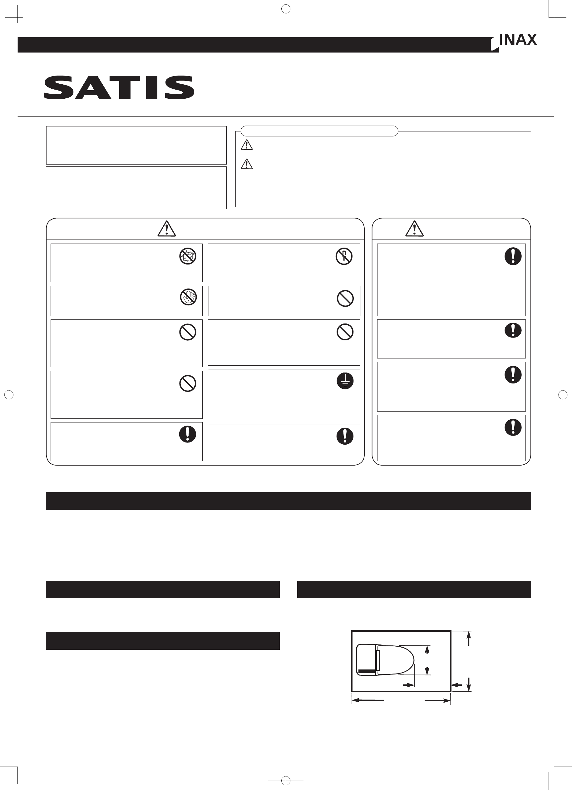
●The amount of space required for this toilet is shown in the following diagram.
At least 400 mm of clear space is required in front of the toilet in order for the
open/close function of the non-touch toilet seat lid to operate correctly.
Minimum Installation Clearance
BE SURE TO FOLLOW
THESE PRECAUTIONS AND
INSTRUCTIONS
These safety precautions are essential for safe
installation and use of the product.
Please read the precautions thoroughly before
installing the product.
Explanation of Terms and Symbols
Absolutely do not allow anyone except
an authorized service technician to
disassemble, repair or modify this product.
*There is danger of electric shock, or re, causing injury.
DON'T
DISASSEMBLE
Do not use any power supply other
than AC 220 V. Do not use any
other method to connect the plug to
an improperly congured receptacle.
*Use of exceeding the rated voltage could cause re.
FORBIDDEN
Thoroughly insert the power plug to
the power point.
* Otherwise, it may cause re or electrify
the user.
OBSERVE
Lead water from a system that
provides drinkable water. If dirt or
impure substances clogs the strainer,
install a lter to the water inlet.
OBSERVE
Do not use a receptacle that is loose and
in which the plug does not t snugly.
*There is danger of electric shock or re.
FORBIDDEN
Do not install or leave the main
body or remote controller in a
constantly humid location or
location where water, liquid or
splash may affect them.
FORBIDDEN
Do not pull out or insert the power
plug with wet hands.
*There is danger of electric shock.
NO WET
HAND
Do not pour water or cleanser
inside or on the body and remote
control, or on the power plug.
*There is danger of electric shock or re.
DON'T POUR
WATER
●
When removing the strainers, be sure
to close the water shutoff valve.
●
When installing the strainers, tighten if
fully until the line is hidden by the body.
*Household articles may get wet if there is water leakage.
OBSERVE
Porcelain is breakable.
●
Before installation, make sure the toilet
bowl is not cracked or otherwise damaged.
●
When installation is completed, check the toilet to
make sure it has not been damaged during the
installation work.
*Damaged parts could cause injury or water
leakage and soaking in the bathroom.
OBSERVE
If freezing weather is anticipated
before handing the product to the
customer, keep the water drained out.
*Freeze damage may cause water leakage or
damage household articles.
OBSERVE
Be sure to adjust the water shutoff
valve and check for water leakage
after installation.
*Household articles may get wet if there is water leakage.
OBSERVE
Make sure that the earth wire is
properly xed.
*Otherwise it may electrify the user in case
of malfunction or a short circuit.
*Consult your electrician if there is no earth terminal
around the power point.
EARTH
Do not nick, damage, carve, bend unduly, pull
on, twist, bind or place heavy objects on top of
the power cord, or pinch it between two objects.
*The above could damage the electrical conductors
and cause electric shock or re.
FORBIDDEN
1050 or more
425
400 or more
(mm)
700 or
more
WARNING···
CAUTION ···
NOTE ···
Indicates a potentially hazardous situation which, if not avoided,
could result in death or serious injury.
Indicates a potentially hazardous situation which, if not avoided,
may result minor or moderate injury or in damage to other
property.
Indicates a potentially hazardous situation, if not avoided, may
result in damage to other product.
WARNING CAUTION
Fasten the supply water line securely so that there is no looseness.
* If it is loose, there is danger of water leakage.
Fasten the supply water line securely!
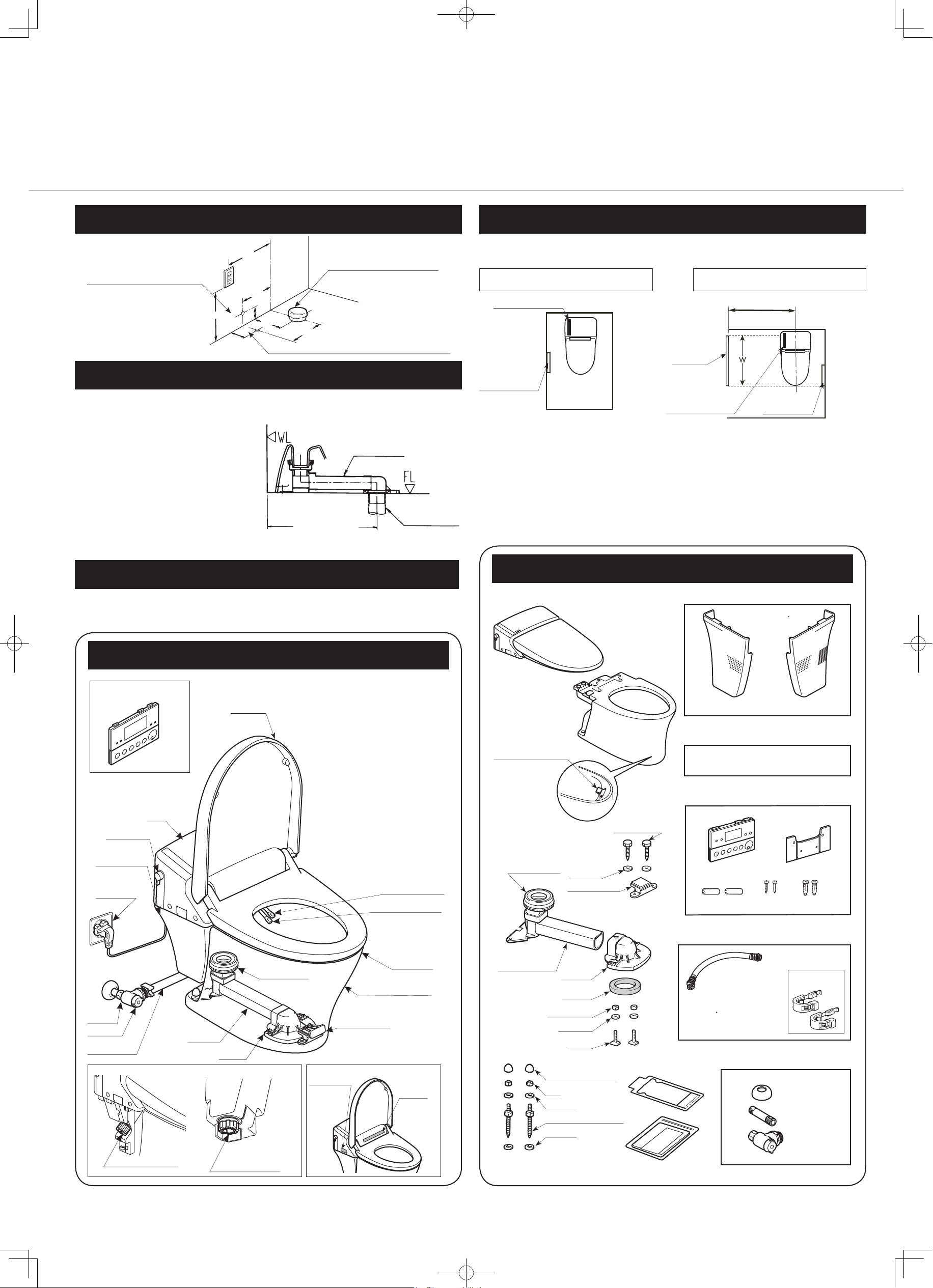
Manual Set
*The deodorizing cartridge has already
been installed in the product.
Toilet Seat (Body)
Side Panel (left)
Side Panel (right)
Batteries (2)
Wood Screw
Plastic Anchor
Water Shutoff
Valve
Water Supply
Pipe
Hemispherical
Face Plate
Water Supply Hose
(400 mm)
Bracket
Remote Control
Unit
Parts Check
(Make sure all the parts are included in the packing box.)
Clip
AY Bolts for
Mounting Parts
Washer
Mounting Base
Adjuster
(Contained in the bottom
of the toilet bowl)
Flange
Gasket
Flange Nut
Washer
T-bolt
Mounting Nut
Decorator Caps (Large)
Nut
Washer
AY Bolts for Anchoring the Toilet
Washer
Installation Pattern Paper
Toilet
Fixing Fastener
(pre-attached to the
toilet bowl)
Available on request
600mm Part No.:322-1050
800mm Part No.:322-1049
Names of Parts
Shower Strainer
Toilet Seat
Water
Shutoff Valve
Power Plug
Shutoff Valve
Flush Lever
Toilet Strainer
(See gure below.)
Body
Water Supply Hose
Toilet Lid
Remote Control Unit
Nozzle (for posterior)
Mounting Base
Nozzle (for bidet)
Shower Strainer
(See gure below.)
Toilet Strainer
Drain Socket
Adjuster
Flange
Rating Label
Caution
Label
To your bottom-right from the front of the body
●Carry out the construction in order beginning with the water shutoff
valve, then proceeding to the body.
●Make sure the distance to the
soil pipe is within a range of
200 and 580 mm. Match up
the adjuster with the distance
to the soil pipe, then cut it and
connect it securely using PVC
cement.
What is the distance to the soil pipe?
Positioning of water supply and drain pipes
Existing soil pipe
200 ~ 580
Adjuster
100
100
280
200~580
280
300 or more
330
Drain pipe
(VP100, VU100, VP75, or VU75)
Water supply 1/2B
(in case of supply from the wall)
Water supply 1/2B (in case of supply from the oor)
Remote
Control Unit
Light Receptor
If the remote control unit is
mounted on the left side wall
If it is necessary to mount the remote controller on the wall opposite to the remote controller receptor,
be sure to conrm that it can receive signals from the installation location before mounting it.
If there is a washstand or other object installed on the side where the remote controller receptor is
located and the remote controller needs to be mounted at a considerable distance from the toilet, the
Satis may not be able to pick up remote controller signals. In such a case, install a screen that can
reect the signals within 1300 mm from the center of the toilet.
*Please prepare the screen on site.
The screen should be at least 1100 mm high and be wide enough to reach the position where the
remote controller is mounted. (However, depending on the wall nish, color and other conditions, the
size of the screen may differ somewhat, so please check to determine the best size.)
As much as possible, install the remote controller on the wall on
the side where the remote controller receptor is located.
Remote Control Unit Mounting Location
If the remote control unit is
mounted on the right side wall
1300 mm or less
Screen
Light Receptor
Remote
Control Unit
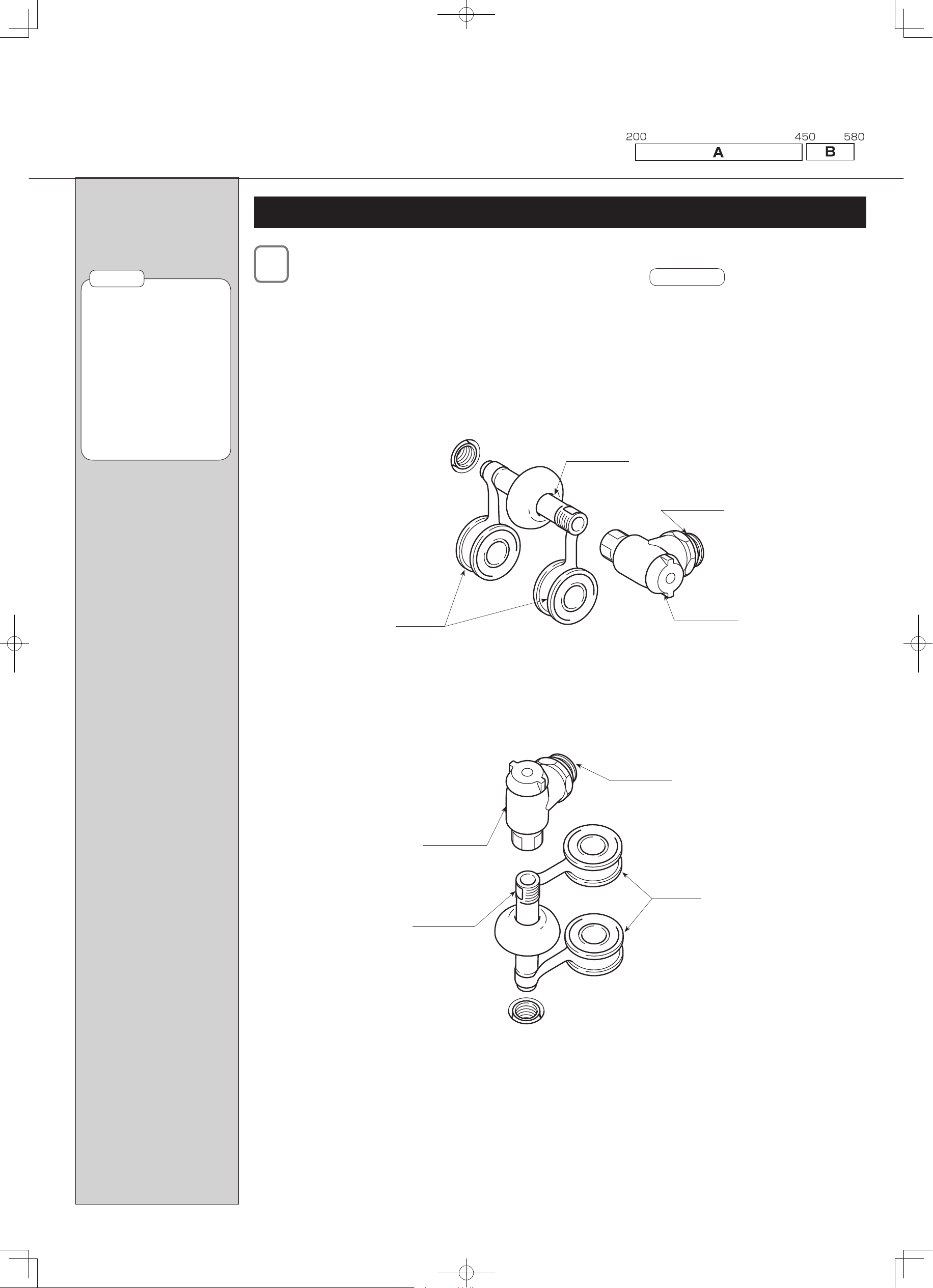
Installation
Installing the Water Shutoff Valve
After nishing the walls and oor, install the water supply pipe and water shutoff valve.
*When installing the water shutoff valve on the water supply pipe, wind some sealing material around the threads,
such as seal tape.
*Tighten the water shutoff valve fully using tools.
In the case of water supply from the oor
Water Shutoff
Valve
Seal Tape
Water Supply
Pipe
Water Supply
Outlet
Seal Tape
In the case of water supply from the wall
Water Supply
Pipe
Water Supply
Outlet
Water Shutoff
Valve
Please note that the following installation steps 4 to 7 varies depending on the distance
between the wall and the centre of the soil pipe.
If the distance is between 200 and 450mm, go to section A.
If the distance is between 451 and 580mm, go to section B.
Distance between the wall and the centre of the soil pipe
See NOTE 1.
Do not get your hand
caught in the water shutoff
valve or step on it.
It could cause the pipe to
become unstable or damage
it, causing water leakage.
There is danger of marring
the wall or the oor.
Install the water supply
outlet in the proper direction
so that the water shutoff
valve won't cause bending
of the water supply hose.
●
*
*
●
NOTE 1
 Loading...